Published by Stanislaw CZAPP, Gdańsk University of Technology. ORCID: 0000-0002-1341-8276
Abstract. The paper presents the principles of residual current devices (RCDs) application in photovoltaic (PV) installations. Provisions of standards in this regard are commented on, in particular, attention is drawn to the lack of obligation to use of RCDs in PV installations. The issue of the shape of the earth fault current and the level of leakage currents in such installations are discussed. These factors influence the selection of RCDs in terms of their rated residual operating current as well as the type of tripping characteristic.
Streszczenie. W artykule przedstawiono zasady stosowania wyłączników różnicowoprądowych (RCDs) w instalacjach fotowoltaicznych (PV). Skomentowano zapisy norm w tym zakresie, w szczególności zwrócono uwagę na brak obowiązku stosowania takich zabezpieczeń w instalacjach PV. Omówiono problematykę kształtu prądu ziemnozwarciowego oraz poziom prądów upływowych charakteryzujący te instalacje – są to czynniki wpływające na dobór znamionowego prądu różnicowego oraz typu charakterystyki wyzwalania wyłączników różnicowoprądowych. (Wyłączniki różnicowoprądowe w instalacjach z fotowoltaicznymi źródłami energii).
Keywords: photovoltaic installations, protection against electric shock, residual current devices.
Słowa kluczowe: instalacje fotowoltaiczne, ochrona przed porażeniem elektrycznym, wyłączniki różnicowoprądowe.
Introduction
The principles of protection against electric shock in low-voltage installations are included in particular in standard PN-HD 60364-4-41:2017-09 [1]. When considering photovoltaic (PV) installations, the provisions of standards PN-HD 60364-7-712 [2-3] and IEC 60364-7-712:2017-04 [4] should also be taken into account. Standards [2-4] provide a guide for protective measures against electric shock to be used on the DC side and the AC side of installations containing PV energy sources. These standards also contain some guidelines on the use of residual current devices (RCDs). However, the guidelines are quite general and require more detailed comments. Based on the works related to high-frequency earth fault currents [5, 6] and especially waveforms with harmonics [7-10], as well as verification of RCDs [11], the proper operation of RCDs strongly depends on their correct matching to the expected shape of the earth fault current. This is one of the most important aspects that should be considered when selecting RCDs in PV installations.
Therefore, the provisions of standards relating to the protection against electric shock and selection of RCDs in PV installations are presented and commented on below. The problems of RCDs operation in such installations, when DC component in the earth fault current occurs, are also discussed.
Provisions of standards
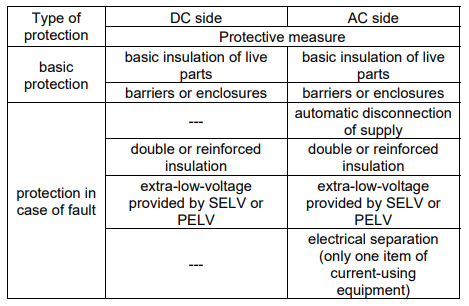
A characteristic feature of PV installations is, among others, that they include both DC voltage and AC voltage circuits. The PN-HD 60364-7-712:2016-05 [3] standard defines permissible measures of protection against electric shock separately for the DC side and the AC side of the installation. Tabl. 1 specifies these measures of protection.
Comparison of the data in Tabl. 1 with the provisions of the standard PN-HD 60364-4-41:2017-09 [1] leads to the conclusion that in PV installations the use of the following protection measures is not allowed:
• for basic protection – obstacles, placing out of reach; (both on DC and AC sides),
• for protection in case of a fault – the automatic disconnection of supply on the DC side, electrical separation on the DC side, non-conducting location (both on DC and AC sides).
With reference to the RCDs’ application, the standard [3] delivers only short provisions in the following clauses:
• 712.53 Protection, isolation, switching, control and monitoring,
• 712.531 Devices for fault protection by automatic disconnection of supply,
• 712.532 Devices for protection against the risk of fire.
Therefore, RCDs may be used on the AC side of PV installations as part of the measure automatic disconnection of supply. They may also be used for protection against the risk of fire. In the aforementioned clauses it is stated that if the RCD is used, its type shall be of B, unless:
• at least a simple separation between the AC side and the DC side is provided by the inverter, or
• at least a simple separation between the RCD and the inverter by a transformer is provided, or
• the construction of the inverter ensures that B-type RCD is not necessary; it should be stated by the inverter’s manufacturer.
Table 1. Measures of protection against electric shock allowed in PV installations, according to PN-HD 60364-7-712:2016-05 [3]
Based on these provisions, it can be concluded that RCDs are not mandatory in PV installations. The point is that if the designer decided to use an RCD in a PV installation without simple separation (but there is no obligation to use RCDs), i.e., in practice in an installation without a transformer, then this RCD should be B-type. Such a type because there may be unidirectional residual currents of low pulsation and other residual current devices (except type B+, which has enhanced residual current detection capabilities in relation to B-type) will not respond to such currents. Examples of simplified earth-fault current waveforms that can be expected in photovoltaic installations are shown in Fig. 1.
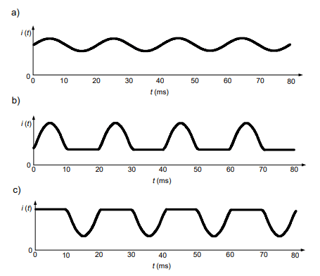
Table 2. Types of RCDs due to the ability to detect a specific waveform shape of the residual current [13, 14] and their usefulness in PV installations
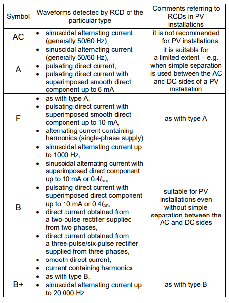
Tabl. 2 shows the types of RCDs and normative shapes of the residual current under which these RCDs are tested. Comments referring to their usefulness in PV installations are included in Tabl. 2 as well.
In the provision of the standard [3], the requirement concerning RCDs does not refer to the obligation to use RCDs in PV installations. It relates to the type of the RCD if it is decided to install it (type B is required to be used, not, for example, type A or type AC).
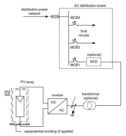
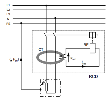
RCDs, if installed, are usually utilized to ensure the automatic disconnection of supply in case of an insulation fault. In the event of an earth fault in the point indicated in Fig. 2, a circuit-breaker MCB1 or an optional RCD has to disconnect the supply. There are no requirements as to the rated residual operating current of the RCD in a PV installation between the inverter and the busbars of the AC distribution board.
In the TN system, the following condition of the effectiveness of protection against electric shock is to be fulfilled:
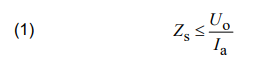
where: Zs – the earth fault loop impedance, Uo – the line-to-earth nominal voltage, Ia – the current giving disconnection of supply with the required time.
Moreover, the circuit with the inverter (Fig. 2) can be considered as a distribution circuit and the automatic disconnection of supply in a TN should occur within a time not exceeding 5s (not 0.4s as for final circuits). This circuit does not require additional protection in the case of direct contact, e.g., such as in typical socket-outlet circuits having a rated current In ≤ 16 A. Therefore, there is also no need to install RCDs of IΔn ≤ 30 mA. Such RCDs may trip unnecessarily due to the high natural leakage currents in the PV system and interrupt the power supply. According to the data included in [15], the leakage currents of a set of PV modules with a rated power of several kilowatts can be within the range 9–45 mA. For this reason, inverters’ manufacturers indicate in their manuals that the rated residual operating current of RCDs in PV installations should not be less than 100 mA or 300 mA. In the case of high-power PV installations, with three-phase inverters, the recommended rated residual operating current may even be higher than 300 mA [16].
If the designer of the electrical installation recommends the application of RCDs for fire protection purposes, then, in accordance with the standards PN-HD 60364-4-42 [17] and PN-HD 60364-5-53 [18], they shall have a rated residual operating current no higher than 300 mA, and shall be installed at the origin of the protected circuit.
It should also be noted that in TN and TT systems, according to PN-HD 60364-4-41 [1] and PN-HD 60364-5-53 [18], the following devices that ensure disconnection of the power supply in the event of a single fault may be used
• overcurrent protective devices (circuit-breakers, fuses),
• residual current devices.
Residual current monitors (RCMs), in principle, give only a signal and are not considered sufficient to provide single fault protection. The standard IEC 62020-1 [19], dedicated to RCM devices, states that the purpose of these devices is only to warn in the event of a residual current exceeding a certain level – they are not protective devices disconnecting the power supply. Monitoring devices (RCMs) embedded in PV inverters are therefore not sufficient for residual current protection if one is to be used in this installation for protection by automatic disconnection of supply. The embedded RCD can be considered a sufficient device and the inverter’s manufacturer should inform about its presence.
Testing of RCDs
If a DC component appears in the residual current waveform, it influences the tripping threshold of RCDs. For this reason, the standard [3] contains a provision that in some cases it is necessary to use B-type RCDs (as given in section ”Provisions of standards”).
Laboratory tests of tripping of RCDs at the residual current containing DC component have been performed. The RCDs have been tested in the presence of the following waveforms:
• AC sinusoidal with superimposed smooth DC component,
• pulsating DC (half-wave) with superimposed smooth DC component.
It was investigated how the tripping threshold of the RCDs changes if a smooth DC component of various values appears in the residual current. The DC component was adjusted to the following values: 0, 6, 15, 30, 60, 90, 150 mA. After adjusting one of the aforementioned values of the DC component, the other component of the residual current (AC sinusoidal or pulsating DC/half-wave) was increased to the point of tripping of the tested RCD.
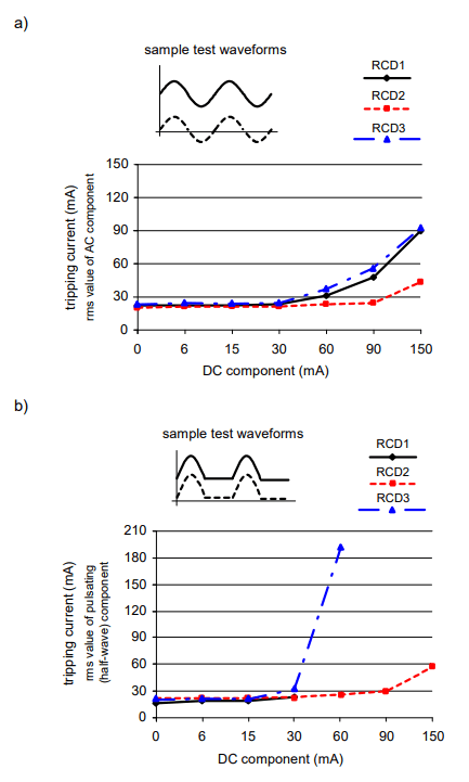
Fig. 3 shows the results of tests of three A-type RCDs with a rated residual operating current of IΔn = 30 mA. In the cases presented in Fig. 3a, there is a noticeable influence of the DC component – the tripping threshold of RCDs increases, but each of the tested RCDs reacted. The best properties has the RCD2. The rms value of the sinusoidal component at which RCD2 tripped did not exceed 30 mA, even when the DC component was 90 mA. The test results presented in Fig. 3b show that the residual current waveform composed of a pulsating DC (half-wave) and a smooth DC component creates more difficult conditions for tripping of RCDs than in the case of a waveform with a sinusoidal component and a smooth DC component. The RCD3 tripped only when the smooth DC component did not exceed 60 mA, and its real tripping current at this value significantly exceeded IΔn. The RCD1 reacted only when the DC component did not exceed 30 mA.
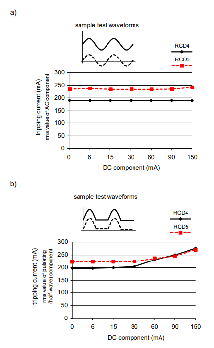
The results of similar tests of RCDs with a rated residual operating current of 300 mA show (Fig. 4) that the influence of the smooth DC component of the above-mentioned values is significantly lower on these RCDs (compared to the 30 mA RCDs). Their real tripping current did not exceed the value of IΔn = 300 mA, even for a DC component equal to 150 mA.
This is due to the fact that for RCDs with IΔn = 300 mA, the DC component 150 mA is only 50% of the rated value IΔn. In the case of RCDs of IΔn = 30 mA, it is as much as 500% (150 mA/30 mA = 5). So, for a given value of the DC component, an RCD with a relatively higher-rated residual operating current (e.g., 300 mA) will behave better than the one of IΔn = 30 mA.
The indicated rising of the RCD tripping threshold is related to the influence of the DC component on the induced voltage in the secondary winding of the current transformer of the RCD. In order for RCD to operate, the secondary current isec of a sufficiently high value has to flow through the relay RE (Fig. 5). This current depends on the induced voltage esec, and that in turn depends on the value, the shape of the residual iΔ (primary ipri) current and the properties of the iron core of the current transformer CT.
Figs 6-8 show the primary current ipri and induced voltage esec oscillograms when:
• there is no smooth DC component superimposed on the half-wave residual/primary waveform (Fig. 6),
• a constant component of 150 mA is superimposed on the half-wave residual/primary waveform (Fig. 7),
• a constant component of 300 mA is superimposed on the half-wave residual/primary waveform (Fig. 8).
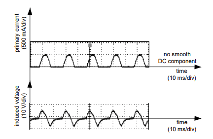
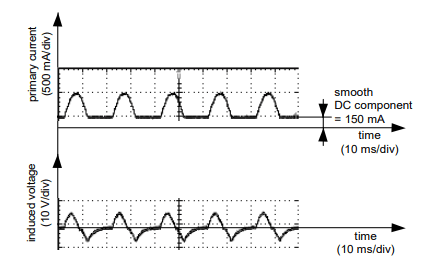
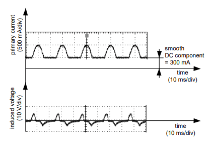
In the case of the last-mentioned composite waveform, a clear change in the shape of the induced voltage can be seen (Fig. 8). This voltage has the lowest value (compared to the waveforms shown in Fig. 6 and Fig. 7), which adversely affects the RCDs’ tripping threshold.
Conclusions
Residual current devices in PV installations are not mandatory equipment. However, if it has been decided to use RCDs, attention should be paid to recommendations of the inverters’ manufacturers regarding the value of the rated residual operating current of RCDs. This value must not be very low to prevent unnecessary disconnection of the PV system, due to leakage currents. The type and properties of the inverter should be analyzed, and the absence or presence of a transformer that galvanically separates the DC side from the AC side should be found, because it may have an influence on the type of the RCD to be used in the PV installation. As can be seen from the analysis presented in this paper, the selection of an RCD of an inappropriate type (e.g., A-type instead of B-type when the DC component has a high value) may result in the lack of effective protection against electric shock in the PV installation – the RCD may have an increased tripping threshold at a high DC component or it may not react at all.
REFERENCES
[1] PN-HD 60364-4-41:2017-09 Low-voltage electrical installations – Part 4-41: Protection for safety – Protection against electric shock
[2] PN-HD 60364-7-712:2006 Electrical installations of buildings – Part 7-712: Requirements for special installations or locations – Solar photovoltaic (PV) power supply systems
[3] PN-HD 60364-7-712:2016-05 Low-voltage electrical installations – Part 7-712: Requirements for special installations or locations – Photovoltaic (PV) systems
[4] IEC 60364-7-712:2017-04 Low-voltage electrical installations – Part 7-712: Requirements for special installations or locations – Solar photovoltaic (PV) power supply systems
[5] Czaja P., Examination of the impact of design of a residual current protective device on the release frequency range, Progress in Applied Electrical Engineering (PAEE), Koscielisko, Poland (2017)
[6] Slangen T. M. H., Lustenhouwer B. R. F., Ćuk V., Cobben J. F. G., The effects of high-frequency residual currents on the operation of residual current devices, 19th Int. Conf. on Renewable Energies and Power Quality (ICREPQ’21), Almeria, Spain (2021)
[7] Sutaria J., Espín-Delgado Á., Rönnberg S., Measurements and modeling of the frequency behavior of residual current devices- from 4 Hz to 40 kHz, Electric Power Systems Research, 209 (2022), 108052
[8] Czapp S., The effect of earth fault current harmonics on tripping of residual current devices, Przeglad Elektrotechniczny, 85 (2009), No. 1, 196-201
[9] Czapp S., The effect of PWM frequency on the effectiveness of protection against electric shock using residual current devices, International School on Nonsinusoidal Currents and Compensation (ISNCC), Lagow, Poland (2010), doi: 10.1109/ISNCC.2010.5524515
[10] Czapp S., Horiszny H., Simulation of residual current devices operation under high frequency residual current, Przeglad Elektrotechniczny, 88 (2012), No. 2, 242-247
[11] Czapp S., Fault loop impedance measurement in low voltage network with residual current devices, Elektronika ir Elektrotechnika, 122 (2012), No. 6, 109-112, doi: https://doi.org/10.5755/j01.eee.122.6.1833
[12] Davids S., Grünebast G., Residual Currents in Photovoltaic Installations, Version 1.1, 2011, Doepke Schaltgeräte
[13] PN-EN 61008-1:2013-05 Residual current operated circuitbreakers without integral overcurrent protection for household and similar uses (RCCBs) – Part 1: General rules
[14] PN-EN 62423:2013-06 Type F and type B residual current operated circuit-breakers with and without integral overcurrent protection for household and similar uses
[15] Leading Leakage Currents. Version 2.6, SMA Solar Technology AG, https://files.sma.de/downloads/Ableitstrom-TIen-26.pdf, accessed on: 24.02.2022
[16] RCD Selection for SolarEdge Inverters – Application Note. SolarEdge, March 2018
[17] PN-HD 60364-4-42:2011 Low-voltage electrical installations – Part 4-42: Protection for safety – Protection against thermal effects
[18] PN-HD 60364-5-53:2016-02 Low-voltage electrical installations – Part 5-53: Selection and erection of electrical equipment – Switchgear and controlgear
[19] IEC 62020-1:2020-04 Electrical accessories – Residual current monitors (RCMs) – Part 1: RCMs for household and similar uses
Author: dr hab. inż. Stanisław Czapp, prof. PG, Gdańsk University of Technology, Faculty of Electrical and Control Engineering, ul. G. Narutowicza 11/12, 80-233 Gdańsk, Poland, E-mail: stanislaw.czapp@pg.edu.pl
Source & Publisher Item Identifier: PRZEGLĄD ELEKTROTECHNICZNY, ISSN 0033-2097, R. 98 NR 12/2022. doi:10.15199/48.2022.12.25
