Published by Mirosław WCIŚLIK, Paweł STRZĄBAŁA, Kielce University of Technology, Department of Electric Engineering, Automatic Control and Computer Science
Abstract. The paper deals a model of the circuit arc furnace designed for electrotechnology or fundamentals of electrical engineering laboratory. This model works at low currents, without high temperature components. In this way, the cooling and dissipation of energy are avoided. This model allows the study of the impact of the supply system restrictions, reactive power compensation problems, harmonic propagation in the system and characteristics verification designated analytically or by simulation.
Streszczenie. W pracy przedstawiono model obwodu pieca łukowego przeznaczony do laboratorium elektrotechnologii lub podstaw elektrotechniki. Model ten pracuje przy niskich prądach, bez elementów o wysokiej temperaturze. W ten sposób unika się układów chłodzenia i rozpraszania energii. Umożliwia on badanie wpływu ograniczeń układu zasilania, problemów kompensacji mocy biernej, generacji harmonicznych w systemie oraz weryfikację charakterystyk wyznaczanych analitycznie lub symulacyjnie. Model fizyczny obwodu elektroenergetycznego trójfazowego pieca łukowego.
Keywords: arc furnace, nonlinear load, rectifier, physical model.
Słowa kluczowe: piec łukowy, obciążenie nieliniowe, prostownik, model fizyczny
Introduction
The quantity of iron and steel production is still an economic potential measure of the country’s development. Industrial steel production started at around 1740 when the crucible process was used. In the steel production market, between 1940 and 1970, four different technologies competed simultaneously in deliveries of steel. Currently, two technologies are used, what follows from the needs of the market. Diffusion of the electric steel process results from scrap recycling, the use of continuous casting of steel and possibilities of steel grades production on request. It is related to far-reaching changes in the structure of the steel industry, due to the small size of the production installation, the availability of steel scrap as a raw material and better energy efficiency compared to the previous open hearth process. About 70% of demand of steel is met by the iron ore reduction process and the carbon-rich melted iron processed into steel using oxygen in the basic oxygen oxide converter process. The process is marked as BOS, BOF or LD. This process is an improved Bessemer process. The open hearth and Bessemer processes were completely replaced by LD and the arc processes arc [1].
The economics aspects of the operation of the furnace, i.e. the reduction of the power consumed by the device per tonne of steel, reduced consumption of the lining and electrodes have been extended to research into ensuring good power quality [2],[3]. This is due to the fact that the arc furnace is a high power load of a stochastic variable nature. As a result, there are frequent changes in the power consumed by the device, which cause flickers. These phenomena occur mainly in the melting phase, and their frequency has range from 0.5 to 30 Hz. As a result of studies it was found that voltage changes of only 0.5% in the range of 6-10 Hz cause flickering of incandescent and discharge lamps perceptible by man. The second unfavourable phenomenon that occurs during the operation of an arc device is related to the high non-linearity of load – electric arcs. As a consequence, higher harmonics are propagated to the mains.
Technical solutions used in modern arc furnaces require the cooperation of specialists in many fields such as metallurgy, electro heating, automatics, power engineering, environmental protection. In the electric steel process, metallurgists have play a dominant role. They are responsible for the final technology of the electro-steel process. However, you should ask the question: Have all the problems of the furnace been resolved? The answer is not positive. The importance of some of them was reduced: using computer control, foamed slag, and liquid metal lake. These problems are particularly related to the electric circuit of the arc furnace. The problems interactions arc furnaces during the smelting process on the energy system and the operating characteristics of the power circuit are still open. In the positioning of the electrodes, complex algorithms are used, not taking into account the feedback circuit and arc voltage measurement accuracy. In order to stabilize phase currents of AC arc furnaces, averaged for a few minutes the measured currents is often used. Therefore, we can speak rather of avoiding problems than solving them.
There is a need to do this research in physical form. Therefore, the main objective is to develop an equivalent model of an arc furnace in physical form. The physical model should enable the analysis of the phenomena of higher harmonic propagation and flickering of light in supply network. Such model is proposed. The analyses will be conducted in low-power circuits, thus increasing the safety of persons and reducing the economic costs of conducting research experiments. This model will be useful both for research and teaching purposes.
Physical model of the arc furnace
The electro-energy model of the arc furnace is difficult to implement in simple laboratory conditions. The electric arc furnace is characterized by variable parameters of its operation, chemical and thermal influences harmful to the environment. Therefore an equivalent physical model of such circuit can be useful. In [5] the electronic welding arc imitator was proposed for applications in diagnostics of welding sources. The executive element is controlled by a programmable unit with a mathematical electric arc model. The electric arc characteristics are obtained digitally. As a result it is possible to carry out research in a wide range of currents (without the need to exchange electrodes), with a high speed, easier automation and the lower qualifications of staff. The use of such imitator has many advantages, but in [5] the author focused only on mathematical modeling of electric arc similar as in [6], omitting the problems of physical accomplishment of the model.
To meet these requirements the electrical diagram of the balanced three-phase circuit with nonlinear load is analysed – figure 1. The circuit has not neutral wire. Nonlinear elements in each phase are electric arcs models in the arc furnace. The voltage Uo(t) is the instantaneous value of the potential difference between the star centers of the load and the power source.

Analysis of this circuit with non-linear electric arc model was conducted in [7]. In order to implement of physical model of such a circuit, the nonlinear element in each phase is replaced by Graetz bridge with parallel output capacitor C, isolated DC/DC converter and resistive load RL. The diagram of such circuit is shown in figure 2.

Nonlinear load is described by signum function:
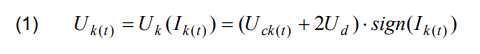
where: k = 1,2,3 is the phase number, Ud – forward voltage of rectifier diode.
For balanced three phase circuit from figure 2, the equations for circuit can be obtain on the basis equation for single phase. The equation for one phase can be written in the following form:
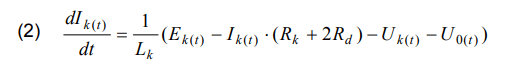
where Rd is series resistance of the rectifier diode.
The supply voltage is described:

where Ѱ is the phase shiftment angle between supply voltage and first harmonics of the load voltages. The voltage U0(t) is:

Connecting the resistance load RLk to the rectifier output without DC-DC converter the second equation has the form:

Waveforms of circuit for single phase shown in the figure 3. The output voltage fluctuations are small for a large capacitor. The voltage on the rectifier as seen from the power supply terminals is similar to the signum function.
For elimination of interference and separation of electrical ground, isolated DC/DC converter is used. Isolated DC-DC converter with push-pull topology is shown in figure 4. The DC voltage VIN is converted to the high frequency AC voltage by using SN6501 module and next converted to the voltage level in the transformer Tr1 with split winding. This circuit is called a DC/DC transformer driver. Secondary voltages of transformer Tr1 are rectified and filtered in a low pass LC filter [8].

The control block SN6501 is a specialized integrated circuit manufactured by Texas Instruments, equipped with power transistors Q1 and Q2, cooperating with a transformer with divided primary and secondary winding [9]. Asynchronous frequency divider generates two complementary output signals with input frequencies fOSC. The logical BBM (break-before-make) protects against simultaneous switching on of two transistors and ensures dead time between transistor switching on.
Simulation of circuit in MATLAB/Simulink
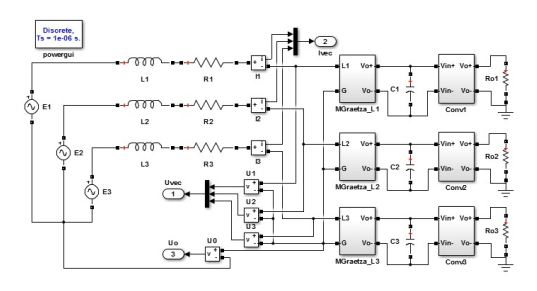
Simulation of circuit from figure 2 was carried out in MATLAB/Simulink system. The SimPowerSystem package was used. The diagram of circuit created in Simulink is shown in figure 5. Blocks MGraetza_L1, MGraetza _L2 and MGraetza _L3 include bridge rectifiers connected in star. Rectifiers are supplied from balanced source AC voltage through inductances Lk and resistance Rk, where k = 1,2,3 and is the phase number. Balanced three-phase voltage source created with voltages source and phase shiftment equal 120°. The output ports Ivec, Uvec, Uo – are respectively vectors of instantaneous values phase current, voltages on the rectifier by AC side and voltage potential difference between the center points of the power source and the load. The DC-DC converters are denoted by Conv1,Conv2 and Conv3 blocks. The outputs of these converter are loaded by resistors RL1, RL2 and RL3. These resistive loads are connected by common ground, isolated from rest of the circuit. The diagram of isolated DC/DC converter from figure 3 in Simulink is presented in figure 6.

The transformer driver circuit is performed by pulse generator, Pulse1 and Pulse2, which control power transistor T1 and T2. The ideal multi-winding transformer was used, without taking into account the saturation phenomenon of the core.
Waveforms of voltages and currents in analysed circuit
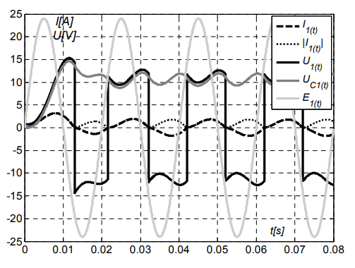
The waveforms of voltages and currents in circuit are shown in figures 7-9. The circuit parameters are as follows: supply voltage Es=24V, series inductance Lk=30mH and Rk=1mΩ in each phase. It was assumed that C1=C2=C3=2mF and RL1=RL1=RL1=15Ω. Forward voltage of the diodes are 0,7V. The switching frequency of the transistors T1 and T2 is equal 10 kHz with duty cycle 50 %. Series resistance of the transistors and diodes is 0,1 Ω. Simulations were carried out with a constant step time equal to 1μs.

Transient processes are visible at the moment turn on power supply. The peak currents are higher than in steady state. In the steady state, the shape of currents is similar to sinusoidal. The waveforms of voltages U1, U2, U3 on the nonlinear loads in each phase are similar to signum function. Amplitude of signum function in this case is sum of output voltage and forward voltage of two diodes. These waveforms are rectangular wave with accuracy to the fluctuations of the output voltage rectifiers.


The obtained instantaneous waveforms of the circuit for resistive load, prove that power circuit of arc furnace may be modelled using bridge rectifiers. Characteristics of bridge rectifier as seen from AC voltage source is signum function of supply current. This characteristic can be further shaped by replacing the resistive load with the computer controlled transistor.
Conclusions
Physical model of the three phase circuit allowing analysis interaction of arc furnace and power system we can realize modeling arc furnace by using simple elements, bridge rectifier and isolated DC/DC converter. Characteristics of such load are similar to signum function. The model can be used in the laboratory and is a basis for analysis of the impact of such load on the power system. The components are designed to work at low currents and without the use of high temperature components. Therefore, cooling systems is not necessary. The resulting instantaneous waveforms of currents and voltages in this circuit are similar to the waveforms in electric arc real circuit.
REFERENCES
[1] Teoh L.L.: Improving environmental performance in mini-mills, Steel Times Intemational, March 1991
[2] Wciślik M., Kazała R.: Symulacja wpływu zakłóceń długości łuku na charakterystyki obwodu pieca łukowego. Zeszyty Naukowe Politechniki Świętokrzyskiej: Elektryka 38, Kielce 2000.
[3] Gomez A., Durango J., Mejia A.: Electric Arc Furnace Modeling for Power Quality Analysis, IEEE ANDESCON 2010
[4] Warecki J., Gajdzica M.: Załączanie transformatora pieca łukowego w sieci z układem filtrów wyższych harmonicznych. Przegląd Elektrotechniczny, ISSN 0033-2097, R. 91 NR 4/2015
[5] Sawicki A.: Imitatory łuków w diagnostyce źródeł spawalniczych, XLIX Międzyuczelniana Konferencja Metrologów MKM 2017. Zeszyty naukowe Wydziału Elektrotechniki i Automatyki Politechniki Gdańskiej Nr 54, s. 195-198, 2017
[6] Wciślik M.: Analityczne modele łuku elektrycznego, Przegląd Elektrotechniczny, ISSN 0033-2097, R. 84 NR 7/2008.
[7] Wciślik M.: Elektrotechnika pieców łukowych prądu przemiennego – zagadnienia wybrane. Politechnika Świętokrzyska, Kielce 2011
[8] Dokic B. L., Blanusa B.: Power Electronics Converters and Regulators, Springer, Switzerland 2015
[9] Texas Instruments: SN6501 Transformer Driver for Isolated Power Supplies, 2014
Authors: Professor Mirosław Wciślik, Kielce University of Technology, Department of Electric Engineering, Automatic Control and Computer Science, al. Tysiąclecia Państwa Polskiego 7, 25- 314 Kielce, E-mail: wcislik@tu.kielce.pl; MSc Paweł Strząbała, Kielce University of Technology, Department of Electric Engineering, Automatic Control and Computer Science, al. Tysiąclecia Państwa Polskiego 7, 25-314 Kielce, E-mail: pstrzabala@tu.kielce.pl
Source & Publisher Item Identifier: PRZEGLĄD ELEKTROTECHNICZNY, ISSN 0033-2097, R. 94 NR 4/2018. doi:10.15199/48.2018.04.26
