Published by Lauri Kütt, Eero Saarijärvi, Matti Lehtonen, Department of Electrical Engineering Aalto University School of Electrical Engineering, Espoo, Finland. lauri.kutt@aalto.fi, eero.saarijarvi@aalto.fi
Heigo Mõlder, Jaan Niitsoo, Department of Electrical Engineering, Tallinn University of Technology Tallinn, Estonia
Abstract—For wide use of electric vehicles (EVs), there are different aspects of the electric power system to consider for making it ready for the increased load by battery charging. The topics include power production, peak load management, distribution transmission capacity but also distribution network power quality and many more. This paper presents an overview on the likely power quality impacts in the distribution networks associated with EV charging. Based on a literature review, focus is especially put on harmonics and load unbalance in the network. Most relevant papers observing these topics are presented summarizing their contribution. The power quality aspects in distribution networks discussed here are not often presented within analysis of permissible EV penetration levels. Harmonics or voltage unbalance and effects associated with these could introduce additional limits to the EV charging capacity for the distribution networks. Therefore the analysis on the EV charging influence on these power quality topics requires also high-priority discussions before drawing conclusions on the distribution networks capabilities.
Keywords-electric vehicles, battery charger, power quality, harmonics, harmonic distortion, voltage unbalance
I. INTRODUCTION
Electrical vehicles are considered everyday use commuter vehicles with significant on-board energy storage and can use the mains power supply for charging the energy storage. Typical such vehicles are battery electric vehicles (BEVs) and plug-in hybrid vehicles (PHEVs). Due to similarity of the process of the on-board battery charging, there would be only slight differences in the impact for the power networks depending on the vehicle type. Therefore, within this paper, all such vehicles are referred to only as electric vehicles (EVs).
Typical EVs are provided with batteries having energy storage capacities from some kWh up to several tens of kWh [1]. Accounting losses, charging such batteries means even higher energy usage from distribution network. It has to be kept in mind that for providing acceptable convenience level for the EV owner the battery would require full recharge in time of just limited hours. To accomplish this, power of the chargers is expected to be high, starting from 1.6 kW for single phase onboard chargers for home use [2] reaching into hundreds of kW for ultrafast charging [3]. As the most probable location for EV charging is home [4] the likelihood of addition of powerful single-phase loads to the residential network is very high.
The increasing use of EVs is being promoted actively for several benefits in environmental aspects and energy efficiency. Assuming thermal power plant origin of power, overall EV efficiency is at least 23,1% [5] while a vehicle with internal combustion engine utilizes 12,5% of fuel primary energy. Besides higher efficiency, the EVs can offer additional cost effectiveness and other benefits. Discussions in public are however not regarding the effects to electrical networks and it is often presumed that the distribution networks provide the necessary overhead and are ready to accept the EV charging loads [6]. The distribution network transfer capacity availability has recently seen quite much discussion, with results presenting clearly that the distribution networks can have limitations in EV charging [7] [8] support even for a relatively low EV penetration levels. As a remedy, several control and moreover smart charging scenarios have been proposed to increase the charging capabilities to the network [9].
Topics for the analysis of EV charging impacts to distribution networks can be listed as thermal loading, voltage regulation, harmonic distortion levels, unbalances, losses and transformers loss of life [10]. This paper aims to summarize the investigation presented until now about the aspects of harmonics and load unbalance associated with EV charging. For an introduction, a summary is provided about the harmonic currents produced by the EV chargers. Here the expected harmonic distortion and power levels for chargers are described, also case measurement results are provided. This is followed by a discussion about the summation of harmonic currents and the harmonic voltages seen in the distribution networks. Some remedies are discussed to decrease the harmonic currents levels. In the last part the studies of network voltage unbalance are discussed.
The focus of the distribution networks in this paper is put on the residential networks, where the EV charging could bring severe addition of power electronic load and associated power quality issues. Industrial networks are not observed at this time as usually the industrial networks have their own power supply network and rather company specific loads. Residential networks however supply a large number of customers and failures to meet supply standards may result in high customer dissatisfaction.
II. REQUIREMENTS FOR THE EV CHARGERS AND NETWORKS
In Europe, most common standard for public power supply is EN 50160 [11], which sets conditions for
• voltage magnitude variation,
• voltage harmonics,
• interharmonic voltage,
• voltage unbalance
and many more. All loads that are connected to the power network must provide so low effect on the network that it does not lead to violation of the power supply conditions stated in this standard. This means also that the EV charger, once connected to public network, must not influence the network operation to the extent that can cause deviation from the standard. It should be kept in mind that parameter variations beyond standard limits can cause malfunction and failure of different devices connected to network.
The requirements for the EV chargers specifically are not standardized at this time. In general, the EV chargers have to fulfill requirements for loads that can be connected to electric power network described by electromagnetic compatibility IEC 61000 series standards (and similar IEEE standards in USA). These standards set the emission levels, including the harmonic currents, power factor etc. that a charger is allowed to have. The standards applying for the low-power EV chargers are IEC 61000-3-2 [12] and IEC 61000-3-4 [13], which set limits to the harmonic emissions generated by the charger.
Limits for voltage unbalance in LV networks are provided in standard IEC 61000-2-2 [14]. In general, the permissible level in the networks is 2%, but the question is somewhat more complex. The voltage unbalance is a result of unequal phase currents and the control of the phase currents is possible generally for the three-phase chargers. A greater problem would arise from the use of large number of single-phase chargers in the network, which can still provide presence of significant unbalance.
III. CHARGER HARMONICS
Every non-linear load is expected to provide a harmonic pattern, meaning specific harmonic magnitude and phase values. The quantitative amount of current waveform harmonics can be expressed as the total current harmonic distortion (THDi)

where h is the harmonic order number, H is the highest number of harmonic observed, Ih is the RMS-value of the current h-th harmonic component and I1 is the mains frequency current component RMS value. Similarly, the total voltage harmonic distortion THDv is calculated, but with the current values in (1) replaced with respective voltage values.
EV battery requires DC for charging and the conversion from AC as well as charging control is provided by the power electronics converters, presenting non-linear load. The harmonics associated with the EV charging are closely related to the charger circuit topology that is providing an interface towards the AC network. The simplest single-phase full-bridge rectifier, or for higher power ratings three-phase diode rectifier, (similar to all uncontrolled rectifiers) provide the highest current harmonics to the AC power network. The circuits and control strategies have evolved rapidly to include more network friendly features, such as power factor correction (PFC) and current waveform shaping. Evolution of the rectifiers’ topologies, the associated waveforms and the current harmonics levels have been laid out in [15]. Authors have relied on real measurements of different chargers, presenting actual waveforms that provide good information on possible charger topology. First chargers measurements from 1993 revealed use of uncontrolled or low-control rectifiers, revealing average THDi of 50%. Measurements of 1994 commercially offered EVs present average THDi of 20%, while the EVs tested in 1995 presented near-sinusoidal current waveforms and THDi below 7.5%. It should be pointed out that the chargers with high THDi present the older topologies, not likely present for the modern vehicles.
More recent analysis, presented in [16] for different controlled battery charger front ends using modern power semiconductors, shows that there is a variety of topologies offering THDi well below 5% at load of 50…100% of rated power. The harmonics levels would remain lower than the limitations by applicable standards. The power factor at the same is time greater than 0.99. However, there seems to be slight dependence between the harmonic levels and input voltage levels. With higher charger input voltage, the lower harmonics (below 13th) are at slightly higher level, while for the lower mains voltage the higher harmonics (above 15th) present higher values. The practical measurements of modern commercial EVs in [17] present charging THDi of 11.6%, similar to results in [18]. There is also a rather good example of a commercial EV with a charger providing around 4.5% THDi presented in [19]. A calculation for the standard limits of the harmonic emissions has been presented in [20]. Based on the limits in IEC 61000-3-4 [13] for individual harmonic emission levels, the highest THDi allowed for a charger would be 17.3%. Comparing only THDi, the modern EVs could fit nicely in the standard limits. It has to be pointed out that the THDi does not reveal the levels of the individual harmonics, which could still exceed the limits regardless of THDi value.
A comparison of the charger harmonics typically indicated is presented in Table I.
TABLE I. COMPARISON OF EV CHARGERS HARMONIC DISTORTION LEVELS

IV. CHARGING PROCESS
Different battery types and their charging cycles have been presented in [23] comparing lead-acid batteries and Li-ion batteries charging cycles and charger operation. Lead-acid, not very widely used in modern EVs due to heavy mass, has 4 different charging stages, with low, medium, topping and trickle modes. Li-ion type batteries would follow charging patterns fast-topping-trickle. Although the lead-acid battery charger shown is three-phase and Li-ion single-phase, it might be reasonable to assume that the chargers would present similar current waveforms regardless of the battery chemistry. It has been presented that the THDi during the heavier charging load is lower than during the low (trickle) load, discussed also in [24]. The conclusion, that the current waveform degradation in the low-power mode would be more harmful considering losses and distortions in the distribution networks, cannot be agreed with. It does not take into account the fact, that in low-power operation load current as well as harmonics have smaller magnitudes, which means that the effect to the network, on the contrary, is weaker. This has been presented with practical measurements of another commercial EV using the built-in charger [18]. Results show rather constant THDi value of 11% over the entire range of charging power, with a slight increase for the near-full capacity. However, it can be seen from the associated voltage THD measurements, that when the charging current decreases and THDi increases, THDv instead decreases. Also in the same paper a three-phase more powerful charging has been observed, with clearly observable relation of THDi increasing as the charging current decreases.
In [25] a charging profile has been proposed from measurements of EV charger, also used in many other papers, presenting constant current and then constant voltage charging operation. The particular measured data shows difference in waveforms considering different state of charge (SOC). Again, the THDi is higher when the battery is approaching the complete charge and the output power of the charger drops. Different charging power profiles with measurements of 5 different EVs have been presented [26]. The charger control methods for different EVs are likely very different, as the charging times vary. Similarly the charging current profiles follow different patterns. The chargers observed are modern chargers, with PFC likely included, as the true power factor is specified in most cases as very close to unity.
V. HARMONIC CURRENTS FOR MULTIPLE CHARGERS
A typical distribution network has a large number of different non-linear loads connected to it. Adding different manufacturers’ EV chargers, it is likely that there are a variety of different harmonic patterns present. The diversity of the patterns may lead to notable harmonic cancellation. This effect occurs when harmonics with different phase angles provide a sum in the magnitude that is smaller than the individual harmonics magnitudes. It is still rather complicated to evaluate this effect. Cancellation is more probable as the number of consumers increases [24]. It has also been indicated that harmonic cancellation is more expected at higher harmonic orders, which can then account for the relatively minor THDi decrease observed in different studies. In most papers, it is rather common, that only the harmonics levels are observed, as the utilities are required to keep the harmonics levels under a given limit. If diversity of chargers is not taken into account, the harmonic problems could be overestimated [27].
For the correct estimation of the harmonics levels and cancellation, phase angle values of individual harmonics are also required besides magnitudes. An example of a more sophisticated model allowing observing harmonics cancellation due to diversity in magnitudes and phase angles has been presented in [27]. One of the pilot papers in this area is [28] where multiple different EV chargers in the network have been observed. There are 5 different rather simple charger topologies described, assigned for samples of EVs. Several probabilistic parameters are included such as distribution of charging times and SOC. Monte Carlo simulation method with sample size of 100 is used for the analysis of the complex system. It is reported, that 10% smaller harmonic current magnitudes were seen compared to the simple summing of magnitudes.
In [25] the measurement results of charging process have been presented, with analysis performed by dividing the harmonics into real and imaginary parts, observed up to 15th harmonic. Identical chargers are observed, however with waveform and THDi dependent on the battery SOC, which could also be observed as different chargers in the network. Similar to [28], the battery state and also charging start time have been observed as stochastic parameters. A model has been defined taking into account the probability density functions and solution has been found using analytical and the Monte Carlo method. A good convergence has been achieved with sample size of 7 chargers. Monte Carlo method has also been used in [29] where convergence is presented with a slightly larger sample size of 25. This would mean that this amount of different chargers could provide the harmonic cancellation already near the maximum possible value. The THDi decrease from 27.5% down to 25.1% due to diversity has been stated, which is almost 10% improvement.
Analysis with real and imaginary components for each harmonic has been described in [30]. The paper presents rather powerful chargers with THDi over 40% at connection point. The 11 kV medium-voltage network has been simulated with 36 chargers, each at power level of 8.2 kVA, which makes it difficult to witness the total cancellation effect. Similar approach in [31] uses real measurements of 30 kW charger currents. Charger current waveform indicates significant high frequency harmonics content. The analysis aims to develop a probabilistic method for evaluation of the current waveform. However as the chargers are assumed all the same and other simplifications are introduced, the result does not provide good indications of benefits of the probabilistic approach.
In conclusion, many studies have presented that the harmonic cancellation between different chargers and loads brings the expected EV charging harmonic current magnitude lower. The view on the network has been rather simplified and ideal, with networks only having EV charging load. However, there is still a lack of overview on the matter to what extent actually the harmonic cancellation could reach, assuming background with real everyday loads connected. These loads have their own specific harmonic patterns that can contribute to the harmonic cancellation.
VI. HARMONIC VOLTAGE LEVELS
The harmonic currents can cause presence of significant harmonic voltages. Prediction of levels of voltage distortions has been analyzed in [27], taking into account the probabilistic characteristic of the EV charging currents. The worst case scenario with least residential linear load available during nighttime is targeted. EV penetration of 50% is assumed and voltage distortion is calculated for individual buses. The method presented gives a probabilistic output, revealing the expected probability of a voltage distortion above allowed value. Seasonal varieties have also been accounted as two scenarios are presented. This method has its virtue in the fact, that the modern power supply standards [11] require the operation within stricter limits for a specified portion of time. The probabilistic method can be used to determine the probability of each bus to exceed or meet the requirements.
Worst-case scenario of residential network harmonic voltages has been presented in [20] where a smaller LV network with 15 kVA supply transformer is observed. In this investigation, a worst-case waveforms were constructed, using highest permissible limits for a commercial charger set by standard [13], resulting in charger with THDi of 17.3%. The network load also included typical household appliances for balance. Model of the network is comprehensive and takes into account also lengths and types of cables feeding the customers. It is reported that the worst-case scenario with all households having EV presented the THDv from 2.6% to 5.2%. However, for another case with less EV penetration, THDv stable value at 1.5% level has been shown regardless of addition of EV. Measurements of THDv have also been presented for a test site on a real network, indicating THDv over 2% also without the EV charging. More suggestions for a worst-case simulation have been presented in [32] for a larger network, where also the network is observed not as a lumped model but the effects of cables have been included. THDv is also dependent on the harmonic voltage drop on the cables, due to harmonic current present in the cable. This way, the THDv can be estimated for the consumer furthest away from the supplying transformer.
VII. STRESS ON THE NETWORK COMPONENTS
Harmonic effects in distribution networks cause additional stress on the network components due to the increased harmonic currents and voltages. The components to suffer the most are the distribution transformers, cables and fuses [24]. The most direct effect would be seen with the distribution transformers, which could encounter much greater stress and heating due to the increased harmonic losses but also increased load due to EV charging. The direct approach to the harmonic losses has been presented in [22] where a three-leg distribution transformer is observed using electromagnetic model of the transformer. The 2 MVA transformer is observed under a load of 8 rapid chargers, each with maximum power of 250 kVA. Charging stations present ideal 3-phase rectifier load, with THDi at 24% level. The losses in the transformer are analyzed throughout the day, with greatest variability of losses due to winding losses. The core losses are presented rather stable regardless of load. The comparison is provided in reference to the same transformer being loaded with equal sinusoidal current. In general, operation with high harmonics would bring 6% higher losses than in the case of sinusoidal current. It has been estimated in [24] that total harmonic current distortions level of 70% could bring increase in transformer lifetime consumption by up to 10%. A quadratic relation to between harmonic level and transformer loss of life is proposed.
For maintaining the network components operation or lifetime with presence of harmonics the allowed load is decreased. Higher derating is needed to mostly for the transformers. It has been concluded that the cables do not require as large derating [24]. Another problem emerging from presence of harmonics and voltage unbalance is the neutral wire current [33], which can become large and pose risks if overloaded. Approach on neutral current evaluation due to the EV charging has been presented in [21].
VIII. REMEDIES AGAINST HARMONICS
As a remedy to the high THDi, introduction of some filtering components is one of the solutions. In [34] authors have been investigating single and three-phase chargers with the addition of series reactors. The simulations presented show that for single-phase rectifier there is little effect by the series reactor, while for the three-phase charger the reactor can provide THDi improvement of 50%. In the same paper, some investigation for shunt active filters for a larger parking facility has been presented. In addition to THDi decrease, the reduction of harmonic currents is indicated to provide a decrease of the neutral currents from 56 A down to 5 A. However, neither network parameters nor configuration have been presented for deeper insight. Options to use dedicated harmonic suppression filters have been discussed in [35]. The harmonic current source in the studied case is a EV three-phase charger. For the three-phase rectifier topology is has been presented that 5th and 7th harmonic frequency single-tuned filters are providing a good remedy. This filtering option has been presented for the large-power charging stations, while it is mentioned that generally the small-power charging there would be no need for any filters.
The uncontrolled charging can be regarded for providing the worst-case charging load currents. The analysis of current harmonic distortion during uncontrolled charging and the possible decrease during controlled charging has been analyzed in [36]. The simulation observes an IEEE 19 bus system with transformer having 100 kVA power rating. Charger used has rather high THDi of 31.9%. Uncoordinated charging at low EV penetration results in THDi of 12%, while for coordinated charging this is at 6%. For the implementation of charging control for the real networks, however, some discussions on the targets would be necessary. Next step in charging control is controlled charging and an approach to use smart charging control for asset protection has been presented in [37]. The power quality improvement strategy is proposed for protecting the components most prone to bad power quality. Derating of distribution transformer operating power in case of high harmonic currents is evaluated with the K-factor method. Smart load management with in-house priority system is proposed, accompanied by a smart meter for the control. The rescheduling of EV charging using the smart load management has been shown to provide significant THDi reduction, for the benefit of transformer health.
IX. PHASE UNBALANCE
The unbalanced voltage in three-phase network can be observed as a sum of positive, negative and zero sequence voltage components. The voltage unbalance is commonly observed as negative sequence unbalance, a relation of negative sequence voltage to positive sequence voltage
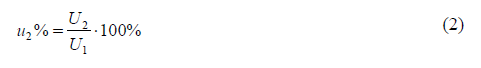
where U1 is the positive sequence voltage and U2 is the negative sequence voltage of frequency 50 or 60 Hz.
The EV chargers most likely to be deployed would be the single-phase chargers found onboard the EVs. It is likely that for a large number of customers and three-phase system, the charging current would be distributed uniformly among the phases. There is still a possibility that given the stochastic characteristic of the charging, there could be some time instances when the charging current is loading the phases unequally. The current imbalance will in turn cause voltage unbalance on the distribution transformer.
During simulation presented in [38], the current and resulting voltage unbalance have been observed for a car park. Relatively high power transformer (1 MVA) was employed only for the supply of 140 units EV single-phase chargers with rated current of 10 A. For this configuration the expected phase current imbalance expected was up to 13%. The voltage unbalance limit was set at 1.3% and it was presented that current imbalance over 11% level would cause the voltage unbalance that would exceed the limit. In a comprehensive analysis in [26] the authors have presented also the typical LV network background voltage unbalance. For some periods, the voltage unbalance even without EVs shows values above 1% level. Comparing to standards for compatibility levels of 2% in LV networks [14], there is still some headroom, though not very much. The analysis has been presented, using random single-phase load placement on the network with 200 customers supplied by 400 kVA transformer with 1000 variations introduced. Different case simulation results are provided, with conditions set on maximum phase unbalance power of 100 kVA or voltage drop of 10% in the network. It is presented that while for the 5 A currents the expected unbalance is quite low, multiple single-phase loads with 20 A load current are more likely to cause unbalance over 1%.
Voltage unbalance analysis in [39] uses the voltage unbalance sensitivity definition. This is a function of EV charging location in the grid and the charging current. Network normal load is modeled as each household on the LV feeder is assumed random power from 0 up to 5 kW. The first case of phase current unbalance is presented with constant uneven load rather than probabilistic approach. At this load configuration, it is reported that there is almost 0.9% voltage unbalance in the beginning and over 1.8% unbalance in the end of the feeder, without the charging load. Adding some 20 A chargers, the near-limit 1.96% value is reached (tolerable 2%). For similar stochastic scenario with Monte Carlo method used, a likely distribution of voltage unbalance in the furthest feeder is presented. It is shown that for 34% of time, it is likely that the 2% voltage unbalance limit is exceeded.
X. DISCUSSION
The EV chargers used in the distribution network would need to fulfill the standard conditions for all loads and it can be shown [40] that if the IEC 61000 standards are met then also it would be ensured that the network operation is meeting the EN 50160 conditions. From the analysis presented, several aspects should still be brought forward. The EV charging differs from other loads, as to long charging times mean long lasting load with high and constant power level, and high coincidence [26]. The EV charger harmonic patterns, and if single-phase chargers are used, the voltage unbalance, could have significant levels for extended period of time.
As the EV charging is more of a stochastic phenomenon, a vast number of different charging and thus load scenarios are available that are possible at any time instance. Therefore, probabilistic approach would be appropriate. The power supply standards themselves, such as EN 50160 [11] are setting the parameters for a specific portion of time (95%) and refer to the probabilistic evaluation of load. The probabilistic methods therefore could be used more directly to evaluate meeting the operation criteria in the power supply standards.
The analysis on the expected harmonic levels is comprehensive; however 2 aspects in the analysis should be discussed. First, the total current harmonic distortion has been referred in several cases as the factor determining the power supply quality. Instead, it should be considered that the voltage harmonic distortion could be a problem. The current distortion as by definition (1) refers to the proportionality of harmonic currents in relation to the mains frequency current component. For determining the impact on the network and the voltage harmonics that are caused by the current harmonics, the actual harmonic current values would have to be used. Second, the modern household devices tend to use more power electronic regulators and converters and therefore an increase of harmonic currents can also be expected even without the EVs charging. It would be interesting to see in the analysis how the actual residential load harmonics and the EV harmonics cancellation occurs.
The voltage unbalance due to heavy single-phase loading, added with high harmonics levels could bring failures due to exceeding power supply standard limits, but for example also due to neutral wire overload. It is therefore necessary that the need for essential reinforcements to the network and sub– stations would be analyzed prior to the large-scale EV deployment. Utilities should consider also the power quality aspects associated with high charging loads with high priority.
REFERENCES
[1] Gan Li, Xiao-Ping Zhang, Modeling of Plug-in Hybrid Electric Vehicle Charging Demand in Probabilistic Power Flow Calculations, IEEE Transactions on Smart Grid, Vol. 3, No. 1, Mar 2012, pp. 492 – 499.
[2] Shengnan Shao, Manisa Pipattanasomporn, Demand Response as a Load Shaping Tool in an Intelligent Grid With Electric Vehicles, IEEE Transactions on Smart Grid, Vol. 2, No. 4, Dec 2011, pp. 624 – 631.
[3] H. Hõimoja, M. Vasiladiotis, S. Grioni, M. Capezzali, A. Rufer, H.B. Püttgen, Toward Ultrafast Charging Solutions of Electric Vehicles, CIGRE 2012, paper C6-207.
[4] L. Zhao, S. Prousch, M. Hübner, A. Moser, Simulation Methods for Assessing Electric Vehicle Impact on Distribution Grids, IEEE PES Transmission and Distribution Conference and Exposition, 2010, 7 p.
[5] C. Roe, J. Meisel, A.P. Meliopoulos, F. Evangelos, T. Overbye, Power System Level Impacts of PHEVs, 42nd Hawaii International Conference on System Sciences, HICSS, 2009, 10 p.
[6] R.C. Green II, L. Wang, M. Alam, The impact of plug-in hybrid electric vehicles on distribution networks: A review and outlook, Renewable and Sustainable Energy Reviews, Vol. 15, Iss. 1, Jan 2011, pp. 544 – 553.
[7] L. Zhao, S. Prousch, M. Hubner, A. Moser, Impact Assessment of Varying Penetrations of Electric Vehicles on Low Voltage Distribution Systems, IEEE PES Transmission and Distribution Conference and Exposition, 2010, 7 p.
[8] V. Tikka, J. Lassila, J. Haakana, J. Partanen, Case Study of the Effects of Electric Vehicle Charging on Grid Loads in an Urban Area, IEEE PES International Conference and Exhibition on Innovative Smart Grid Technologies (ISGT Europe), 2011, 7 p.
[9] Leonor Trovão and Humberto M. Jorge, Power Demand Impacts of the Charging of Electric Vehicles on the Power Distribution Network in a Residential Area, International Youth Conference on Energetics (IYCE), 2011, 6 p.
[10] J. Taylor, A. Maitra, M. Alexander, D. Brooks, M. Duvall, Evaluation of the Impact of Plug-in Electric Vehicle Loading on Distribution System Operations, IEEE Power & Energy Society General Meeting, 2009, 6 p.
[11] EN 50160:2010, Voltage Characteristics in Public Distribution Systems. European standard.
[12] IEC 61000-3-2 ed3.0:2005, Electromagnetic compatibility (EMC) – Part 3-2: Limits – Limits for harmonic current emissions (equipment input current ≤ 16 A per phase).
[13] IEC/TS 61000-3-4 ed1.0:1998, Electromagnetic compatibility (EMC) – Part 3-4: Limits – Limitation of emission of harmonic currents in low voltage power supply systems for equipment with rated current greater than 16 A.
[14] IEC 61000-2-2 ed2.0:2002 Electromagnetic compatibility (EMC) – Part 2-2: Environment – Compatibility levels for low-frequency conducted disturbances and signalling in public low-voltage power supply systems.
[15] S.H. Berisha, G.G. Karady, R. Ahmad, R. Hobbs, D. Karner, Current Harmonics Generated By Electric Vehicle Battery Chargers, International Conference on Power Electronics, Drives and Energy Systems for Industrial Growth, 1996, Vol. 1, pp. 584 – 589.
[16] F. Musavi, M. Edington, W. Eberle, W.G. Dunford, Evaluation and Efficiency Comparison of Front End AC-DC Plug-in Hybrid Charger Topologies, IEEE Transactions on Smart Grid, Vol. 3, No. 1, Mar 2012, pp. 413 – 421.
[17] M. Zamri, C. Wanik, M. Fadzil, M. Siam, A. Ayob, S. Yanto, M. Azah, A. H. Azit, S. Sulaiman, M. Azrin, M. Ali, Z. F. Hussein, A. Kamil, M. Hussin, Harmonic Measurement and Analysis during Electric Vehicle Charging, Engineering, 2013, Vol. 5, No. 1B, pp. 215 – 220.
[18] N. Melo, F. Mira, A. de Almeida, J. Delgado, Integration of PEV in Portuguese Distribution Grid. Analysis of harmonic current emissions in charging points. Electrical Power Quality and Utilisation (EPQU) 2011, 6 p.
[19] C. Wenge, M. Stotzer, T. Winkler, P. Komarnicki, Power quality measurements of electric vehicles in the low voltage power grid, Electrical Power Quality and Utilisation (EPQU), 2011, 5 p.
[20] R. Bass, R. Harley, F. Lambert, V. Rajasekaran, J. Pierce, Residential Harmonic Loads and EV Charging, IEEE Power Engineering Society Winter Meeting, 2001, Vol. 2, pp. 803 – 808.
[21] A.J. Collin, S.Z. Djokic, H.F. Thomas, J. Meyer, Modelling of Electric Vehicle Chargers for Power System Analysis, Electrical Power Quality and Utilisation (EPQU), 2011, 6 p.
[22] P.S. Moses, M.A.S. Masoum, K.M. Smedley, Harmonic Losses and Stresses of Nonlinear Three-Phase Distribution Transformers Serving Plug-In Electric Vehicle Charging Stations, IEEE PES Innovative Smart Grid Technologies (ISGT), 2011, 6 p.
[23] J.P. Trovao, P.G. Pereirinha, L. Trovao, H.M. Jorge, Electric Vehicles Chargers Characterization: Load Demand and Harmonic Distortion, Electrical Power Quality and Utilisation (EPQU), 2011, 7 p.
[24] J.C. Gomez, M.M. Morcos, Impact of EV Battery Chargers on the Power Quality of Distribution Systems, IEEE Transactions on Power Delivery, Vol. 18, No. 3, Jul 2003, pp. 975 – 981.
[25] P.T. Staats, W.M. Grady, A. Arapostathis, R.S. Thallam, A Statistical Method for Predicting the Net Harmonic Currents Generated by a Concentration of Electric Vehicle Battery Chargers, IEEE Transactions on Power Delivery, Vol. 12, No. 3, Jul 1997 , pp. 1258 – 1266.
[26] J. Meyer, S. Hahle, P. Schegner, C. Wald, Impact of electrical car charging on unbalance in public low voltage grids, Electrical Power Quality and Utilisation (EPQU), 2011, 6 p.
[27] P. T. Staats, W.M. Grady, A. Arapostathis, R. S. Thallam, A Statistical Analysis of the Effect of Electric Vehicle Battery Charging on Distribution System Harmonic Voltages, IEEE Transactions on Power Delivery, Vol. 13, No. 2, Apr 1998, pp. 640 – 646.
[28] J.A. Orr, A.E. Emanuel, D.J. Pileggi, Current Harmonics, Voltage Distortion, and Powers Associated with Electric Vehicle Battery Chargers Distributed on the Residential Power System, IEEE Transactions on Industry Applications, Vol. Ia-20, No. 4, Jul/Aug 1984, pp. 727 – 734.
[29] M.S.W. Chan, K-T.T. Chau and C-C.C. Chan, Modeling of Electric Vehicle Chargers, Annual Conference of the IEEE Industrial Electronics Society, IECON 1998, Vol. 1, pp. 433 – 438.
[30] E.W.C. Lo, D. Sustanto, C.C. Fok, Harmonic Load Flow Study for Electric Vehicle Chargers, IEEE International Conference on Power Electronics and Drive Systems, PEDS 1999, pp. 495 – 500.
[31] Lu Yanxia, Jiang Jiuchun, Harmonic Study of Electric Vehicle Chargers, International Conference on Electrical Machines and Systems, ICEMS, 2005, Vol. 3. pp. 2404 – 2407.
[32] V. Monteiro, H. Goncalves, J.L. Afonso, Impact of Electric Vehicles on Power Quality in a Smart Grid Context, Electrical Power Quality and Utilisation (EPQU), 2011, 6 p.
[33] J.J.M. Desmet, I. Sweertvaegher, G. Vanalme, K. Stockman, R.J.M. Belmans, Analysis of the Neutral Conductor Current in a Three- Phase Supplied Network With Nonlinear Single-Phase Loads, IEEE Transactions on Industry Applications, Vol. 39, No. 3, May/Jun 2003, pp. 587 – 593.
[34] J. Balcells, J. Garcia, Impact of Plug-in Electric Vehicles on the Supply Grid, IEEE Vehicle Power and Propulsion Conference (VPPC), 2010, 4 p.
[35] Wenhai Yang, Zhanlong Zhang, Jingmin Wang, Yajing Gao, Simulation of Electric Vehicle Charging Station and Harmonic Treatment, International Conference on Systems and Informatics (ICSAI), 2012, pp. 609 – 613.
[36] S. Deilami, A.S. Masoum, P.S. Moses, M.A.S. Masoum, Voltage Profile and THD Distortion of Residential Network with High Penetration of Plug-in Electrical Vehicles, IEEE PES Innovative Smart Grid Technologies Europe (ISGT Europe), 2010, 6 p.
[37] M.A.S. Masoum, P.S. Moses, S. Deilami, Load Management in Smart Grids Considering Harmonic Distortion and Transformer Derating, IEEE PES Innovative Smart Grid Technologies Europe (ISGT Europe), 2010, 7 p.
[38] G.A. Putrus, P. Suwanapingkarl, D. Johnston, E.C. Bentley, M. Narayana, Impact of Electric Vehicles on Power Distribution Networks, IEEE Vehicle Power and Propulsion Conference, VPPC, 2009, pp. 827 – 831 .
[39] F. Shahnia, A. Ghosh, G. Ledwich, F. Zare, Voltage Unbalance Sensitivity Analysis of Plug-in Electric Vehicles in Distribution Networks, Australasian Universities Power Engineering Conference (AUPEC), 2011, 6 p.
[40] M.N. Moschakis, E.L. Karfopoulos, E.I. Zountouridou, S.A. Papathanassiou, On Adaptation of Electric Vehicle and Microgrid Issues to EMC-Power Quality Standards, Electrical and Electronic Engineering, Vol. 2, No. 5, 2012, pp. 249 – 257.
Source & Publisher Item Identifier: 2013 12th International Conference on Environment and Electrical Engineering. DOI: 10.1109/EEEIC.2013.6549577
