Published by 1. Tomáš ŠKUMÁT1, 2. Žaneta ELESCHOVÁ2,
Západoslovenská distribučná, a. s. (1). Slovak University of Technology in Bratislava (2)
ORCID. 2. 0000-0002-7596-108X
Abstract. This paper focuses on situations in Medium Voltage (MV) grids where a feeder´s breaker failure occurred. This type of fault is quite severe but well handled in higher voltage systems (high voltage, extra high voltage, etc.), basically in looped grids. However, medium voltage grids were built in a different way even in terms of protection relay in power systems, automatics and backups. Several cases of a breaker failure situation have led us to reconsider the existing protection relay scheme used in Západoslovenská distribučná, a. s. (ZSD) – a distribution system operator. The paper also provides suggestions for a real operation – principle of a breaker failure protection by coordination is improved.
Streszczenie. W niniejszym artykule skupiono się na sytuacjach w sieciach średniego napięcia (SN), w których wystąpiła awaria wyłącznika linii zasilającej. Ten rodzaj błędu jest dość poważny, ale dobrze obsługiwany w systemach wyższego napięcia (wysokie napięcie, bardzo wysokie napięcie itp.), zasadniczo w sieciach zapętlonych. Jednak sieci średniego napięcia były budowane w inny sposób nawet w zakresie zabezpieczeń w układach elektroenergetycznych, automatyki i rezerwowania. Kilka przypadków awarii wyłączników skłoniło nas do ponownego rozważenia istniejącego schematu przekaźnika zabezpieczeniowego stosowanego w Západoslovenská distribučná, a. s. (ZSD) – operator systemu dystrybucyjnego. W artykule zawarto również sugestie dotyczące rzeczywistego działania – udoskonalono zasadę działania zabezpieczenia od uszkodzenia wyłącznika przez koordynację. (Prąd składowej przeciwnej jako zabezpieczenie przed uszkodzeniem wyłącznika w sieciach średniego napięcia)
Keywords: breaker failure (BF), circuit breaker, MV grid, protection relay, busbar, fault, negative sequence, protection relay.
Słowa kluczowe: uszkodzenie wyłącznika, prąd składowej przeciwnej
Introduction
A breaker failure (BF) is considered to be a situation, where a circuit breaker (CB) nearest to a fault (selectivity) does not clear the fault for some reason. There may be several reasons why this happens – CB itself can be damaged (extinguishing medium changed its properties), tripping coil is damaged, auxiliary circuits or secondary circuits encounter a problem – some types of CBs for MV use electronic mainboards), protection relay that trips the CB encounters a failure, etc.
Referring to Fig. 1, let us assume, there is a fault between CB 3 and CB 4. Protective relays associated with CB 3 and CB 4, determined to detect faults on the line between these CBs, operate and command CB 3 and CB 4 to trip. In this example, CB 3 fails to interrupt the fault current. Therefore, all sources that continue to supply the fault current through CB 3 need to be interrupted. Assuming sources at stations A and C, CBs 2, 5, and 7 need to be opened locally, or CBs 1, 6, and 8 would need to be opened remotely [1]. Major disadvantages in relation to a remote backup are wider outages (more customers affected), longer clearing time (also time of voltage dip) but the greatest advantage is independency. Local backup is substantially faster but the primary disadvantage of a local breaker failure protection (BFP) is that it may suffer from a common-mode failure [1].

BF can be caused by a variety of situations – a failure to trip or a failure to clear. In the first case, the breaker contacts do not open after the trip circuit has been energized by the protection (“stuck breaker”). In the latter case, the contacts open but the arc is not extinguished and current continues to flow [1].
Common elements of a BF to interrupt the scheme include the following [1]:
• Scheme initiation by a breaker trip signal such as a protective relay that has operated to trip the breaker.
• Determination that the breaker has tripped successfully by monitoring reset of an overcurrent element (50BF) that responds to each measured phase current (50P) and possibly the sum of these phase currents (50G), monitoring change in state of the circuit breaker auxiliary contact (52a, 52b or 52aa), or a combination of these methods.
• A timer.
• Some means to trip and block closing of adjacent breakers.
• Optional – a separate output contact to issue a re-trip signal to the circuit breaker before issuing a breaker failure output with sufficient margin such that successful opening of the circuit breaker will prevent and undesired BF output.
• Optional – a teleprotection channel to key a direct transfer trip (DTT) and to cancel reclosing of remote circuit breakers. In general, there are several BFP schemes [1]:
• Basic BF scheme.
• Basic BF with re-trip logic.
• BF scheme for dual breaker arrangements.
• BF scheme based on 50 BF pickup time.
• BF scheme with two-step timing arrangement.
• BF initiate seal-in.
• BF minimal current scheme.
• Dual timer BF scheme with a fast breaker auxiliary contact and a current detector reset check.
• Triple timer BF scheme.
• Single-phase tripping, BF, and re-trip logic.
• BF timer bypass scheme.
• Current differential BF protection.
• Ground fault BF on both a live tank circuit breaker and a current transformer column failure.
• Series (tandem) breakers.
• BF protection for generator applications.
• Mechanical indication of breaker status (52a).
BF can be a part of [1]:
• Primary protection for an element,
• Feeder, transformer, motor or transmission line protection devices,
• Centralized bus protection devices,
• Distributed bus protection devices
Merits, advantages and disadvantages of integrating BFP with zone protection relays are discussed in [2]. In the [2] methods to improve the security of BFP are also reviewed.
Fundamentals of a local and remote backup protection in combination with real experience from utilities are discussed in [3]. It is also very important to watch a failure rate and take measures where it is inevitable. Issue of reliability characteristics of the 110 kV / MV station and MV switchgears is presented in [4].
BF Protection by Coordination
Faults occur frequently in MV grids. In general, the number of faults increases downstream from a transmission system to a distribution system. Therefore, there is a higher chance of BF.
Looped grids (HV systems, extra HV systems, etc.) were built with a different approach for a breaker failure situation.
The main difference between looped grids and MV grids may be already apparent. On one hand, there is an operational difference and on the other hand, there is also a technological difference. MV grids are operated radially. Wiring between protection relays is not done like in looped grids. There are also different types of protection relays installed – overcurrent instead of distance protections. Busbar differential protection is also not a common protection in MV grids. Feeder´s breaker failure was historically left just to an overcurrent protection relay installed to a feeding transformer [5, 6] – a so called breaker failure protection by coordination. There is one major drawback in this kind of solution – it may be impossible for the backup protection relay to see all faults.
Referring to Fig. 2, let us assume, there is a fault on the feeder with CB4 that has encountered a BF. Backup for this situation is provided by a protection relay that operates CB1
– in general a transformer´s overcurrent protection relay installed on MV side. Simplicity is a very significant advantage in relation to this solution
– no extra equipment, no risk of mis-operation. It is an ultimate protection, which covers all failures, not just BF (failure of CB, relay, settings, controls and wiring, etc.). The main disadvantage is speed – it is a slow type of BF backup.

It is a common practice for distribution, but typically not sufficient for transmission. Solutions for transmission were already mentioned in Introduction. However, the BFP by coordination can be improved by a negative sequence current protection.
MV Feeding Transformer´s Neutral Earthing
There is one major aspect that must be specified, which is HV/MV transformer´s neutral point earthing on the MV side. Basic types are [7]:
• Isolated
• Solid
• Low impedance
• Resonant (compensated)
MV grids in Europe are not operated as solidly grounded [8]. This type of operation is very convenient from economical and maintenance perspective but there is a very severe impact on reliability indicators SAIDI and SAIFI. Other types are common for European MV grids, whereas resonant grounding is very popular indeed. Smaller grids (low capacitive currents of shunt capacitances) can be operated as isolated but with grid expand it becomes meaningless.
Low impedance is mostly used in pure cable grids. Reason for this is very simple – majority of faults are permanent (insulation system breakdown of cables), although there are some pilot projects handling with resonant grounding even in case of pure cable grids – further improvement of reliability indicators. A risk of cross-country fault increases in this case.
There are 3 types of it:
a) Low impedance – low resistance resistor is used.
b) Hybrid – compensated (Petersen coil) and in case of a ground fault a low impedance resistor is temporarily switched in parallel to the coil.
c) Compensated – Petersen coil + auxiliary winding with a secondary resistor.
Type a) is used in pure cable grids.
Type b) is used in grids with majority of cables, but also with some overhead lines – periphery of cities.
Type c) could be used in this case but a primary resistor is kept because a fault location system used in such grids is based on I0 measurement used in ring main units – a primary resistor is a very convenient solution for this method (higher currents during a 1 phase fault in comparison with a secondary resistor). Only the currents are measured – a robust and reliable fault location system used in pure cable grids of ZSD.
There are following basic shunt-type of faults, in relation to Fig. 3:
- One-phase faults
o Ground faults
a) high current
b) temporary high current
c) low current (operational) - Two-phase faults
o Two-phase with ground
o Two-phase
o Cross-country fault - Three-phase faults.
Fig.3. Transformer´s neutral earthing used in ZSD
Negative Sequence – Symmetrical Components
A very common theory and a tool for mathematical and graphical interpretation of asymmetrical phasors in three phase systems is based on symmetrical components. Any three asymmetrical phasors can be replaced by a system of symmetrical phasors (sequences) – positive (index 1), negative (index 2) and zero (index 0) sequence as illustrated in Fig. 4. Phase A is a base.
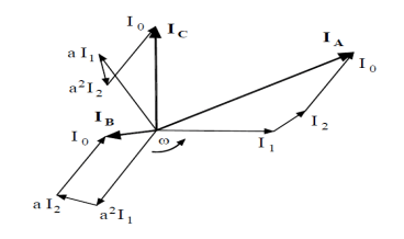

Equations (1), (2), (3) are derived and considered to be a final product, especially the Equation (2) is important for this paper [9].
Analysis of some basic faults mentioned in Chapter II is provided for the purpose of the paper. A simplified grid shown in Fig. 5 is used for the analysis. No load conditions are assumed in the following theoretical analysis. There is a general impedance connected between the earth and the transformer’s neutral point, which is explained more explicitly later. Let us assume that the fault is at the end of the line. Type of the fault is specified in subchapters.

A. Ground Fault – Low Impedance Grounding
Fig. 6 shows sequence circuits for this case. They are connected in series on the basis of the fundamental theory. For analytical and practical purposes, the following assumptions can be applied – transformer´s sequence impedances ZT,1, ZT,2 and ZT,0 can be neglected. Also, line´s sequence impedances ZLine,1, ZLine,2 and ZLine,0 can be neglected. It´s because their values are several times lower in comparison with resistance of grounding resistor – RG (RG >> ZT and RG >> ZL).
What shouldn´t be neglected in general regarding real grids is grid´s shunt impedance (mainly a line to ground capacitance) shown also in Fig. 5. It is apparent from Fig. 6 that the following aspects have impact on I2 magnitude – low impedance grounding resistor, resistance of the fault itself, shunt capacitance of the grid.
Because the distributed capacitive reactances (impedances) ZShunt,1, ZShunt,2 and ZShunt,0 are very large, while the series impedance values ZT,1, ZT,2, ZT,0, ZLine,1, ZLine,2, ZLine,0 are very small, thus, practically, ZShunt,1 is shorted out by ZT,1 + ZLine,1 in the positive sequence network, and ZShunt,2 is shorted out by ZT,2 + ZLine,2 in the negative sequence network. Since these series impedances are very low (they can be neglected as previously mentioned), Z1 and Z2 approach zero relative to the large values of ZShunt,0 and RG.

Moreover, Equations (4), (5) and (6) are derived with the assumption of no load conditions [9] in the fundamental theory. Therefore:

If RF goes to zero, then magnitude of the fault current is:

The real fault recorded by the feeder´s protection relay is shown in Fig. 7 and Fig. 8. The fault was in phase A (in the diagrams L1 marked in green colour). Sequence currents are aligned in phase with the faulted phase A as it is according to the theory. The fault started as a cross-country fault. It is apparent from Fig. 7 – the short circuit current went to several kAs but the protection relay of another feeder cleared it, anyway, after about 60 ms the fault re-appeared, but this time as a single line-to-ground fault. The primary resistor used in this grid limits the current to 600 A.

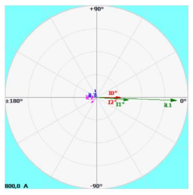
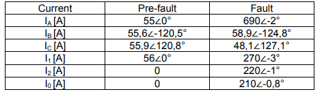
Pre-fault and fault current conditions are compared in Table 1, in relation to the real fault depicted in Fig. 7 and Fig. 8. Highly symmetrical load is apparent.
Table 1. Pre-fault and fault conditions
B. Ground Fault – Resonant Grounding
Fig. 9. shows sequence circuits for this case, i. e. the same connection as in Fig. 6, just a different device connected to a transformer´s neutral point – adjustable Petersen coil (LP) which compensates line to ground capacitive currents of healthy phases in the location of a fault. Sequence currents are as follows:

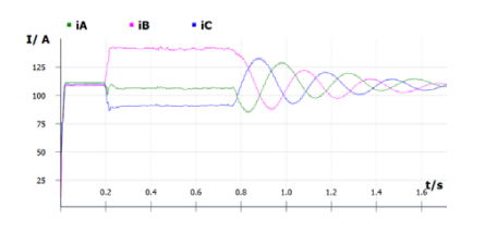
The same assumptions and neglections made in ground fault with low impedance grounding can be applied also in this case with positive, negative and zero sequence impedances of a transformer and a line. Equation (5) for sequence voltages applies also in this case. If XLp – XShunt,0 = 0, then I1 = I2 = I0 = 0. Situation in compensated grids (resonant grounding) is therefore different. After decay of transient phenomena, the new steady-state currents of either healthy or even faulty feeder have operational values. It is apparent from Fig. 10 and Fig. 11. In symmetrical grids, there is almost no I2 current (Fig. 11). Fig. 10 illustrates behaviour of currents after a fault in phase A occurs – the faulted phase A current decreased a bit, the healthy phase B current increased quite a bit and the healthy phase C current decreased a bit. The reason behind this is the following:
• Phase A system´s capacitance is shortened by a ground fault, so the corresponding capacitive current goes to zero.
• There is a shift of healthy phase voltages, the angle between them is not anymore 120°, but 60° and this fact causes also shift in capacitive currents. There is also a change in magnitude of the currents which is √3 higher than a pre-fault per each phase. Both the angle and the magnitude depend on the value of RF.
• Ratio between a load and a capacitive current is also important.

This fact is apparent even from Table 1. However, it is less obvious due to the current of the primary resistor. Throughout the system the distributed capacitance XShunt,1 and XShunt,2 is actually parallel with the series reactances XT, XLine and so on, so that in the system I1 and I2 are not quite equal to I0 in the system [10]. If shunt impedances of the system are symmetrical, then capacitive currents of healthy phases do not contribute to I2 current. This is also apparent from Fig. 11.
However, I2 current would appear temporary – after a primary resistor is switched in parallel with the coil. It is common for the operation that XLp is tuned close to the resonance.
Therefore, in resonant grounded systems, which are symmetrical, I2 would be very low, almost equal to zero. Real fault recorded by a feeder´s protection relay is as follows:
If RF goes to zero, then the fault current is:

Essentially, the fault current is equal just to resistive losses of the system´s shunt impedance, however, the coil must be tuned to resonance. In general, a so called detuning current can be assumed and then the magnitude of IF is:

Pre-fault and fault current conditions are compared in Table 2, in relation to the real fault depicted in Fig. 10 and Fig. 11. Highly symmetrical load is apparent.
Table 2. Pre-fault and fault conditions
C. Line-to-Line
Fault Shunt impedances can be neglected for this type of fault, their contribution to fault current is very small. A fault between phases B-C is considered. The following assumptions applies for the fault – IA = 0, IB = -IC and UfB = UfC (if RF = 0). Therefore, I1 = -I2 and I0 = 0.
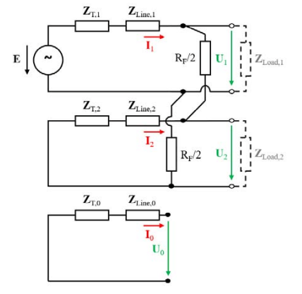
Connection of sequence circuits in Fig. 12 corresponds with the applied assumptions. Equations (11), (12), (13) can be derived from Fig. 12 and the assumptions applied for this type of fault:


Equation (13) shows the major advantage that comes with negative sequence current protection relay – normal overcurrent relay must be set up to x.IN (x.IB), where x starts roughly at 1,2. Negative sequence current relay is more sensitive by a factor of √3.
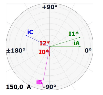
Real fault recorded by a feeder´s protection relay is as follows:


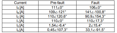
Pre-fault and fault current conditions are compared in Table 3, regarding the real fault depicted in Fig. 13 and Fig. 14. Highly symmetrical load is apparent.
Table 3. Pre-fault and fault conditions

It is apparent that IA increased a bit – this is caused by MV/LV distribution transformers and their windings connection – Dyn or Yzn is used in grids of ZSD. |IB| ≠ |IC| because of load currents.
Load itself can be quite a significant contributor in general regarding the magnitude of I2, however, it is not the case with ZSD´s grids – whole lines are built as three-phase (highly symmetrical shunt impedance / capacitance) and there is no significant 1-phase or 2-phase load connected to the MV grid.
There is I2 during cross-country and a two-phase-to-ground faults. There is no I2 during a three-phase fault according to the theory – a symmetrical fault. It is obvious that I2 protection relay can´t be applied as a general solution according to the theory, but also according to recorded faults.
Aspects Influencing I2 Magnitude
The following aspects and their influence on I2 are analysed for the purpose of this paper – fault´s resistance (RF), line´s length and a special case of asymmetrical load that can occur even in symmetrical grids. Calculations were carried out in Excel based on equations stated in the theoretical chapter. Grid´s line-to-line voltage U = 22 kV, transformer´s SN = 40 MVA. Current´s base for pu system is 1 kA.
The graph in Fig. 15 shows relation between |I2| and RF in grids from Fig. 3 – a) and temporarily in b). Line´s series impedance was neglected in this calculation. When the ratio between a grounding resistor and a cable´s impedance is taken into consideration, then the neglection is acceptable.
It is apparent that I2 magnitude drops relatively fast but one fact must be mentioned – real faults in cable grids and their RF are close to 0. In Fig. 15, there are 3 curves in relation to neutral point resistor´s nominal current. Commonly used values were analysed.

However, line´s impedance shouldn´t be neglected in case of overhead lines. The length of a line is for sure a limiting factor for I2 magnitude in this case. Commonly used AlFe conductors are included in Table 4, where the reactance per kilometer was calculated for a typical conductor arrangement used in MV grids of ZSD.
Table 4. MV AlFe conductors
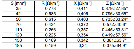
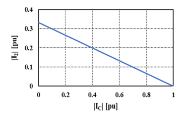
Relation between the length of a line and I2 magnitude is shown in Fig. 16 for a different type of AlFe conductors from Table 4. Line-to-line fault is assumed at the end of a line.

The graph in Fig. 17 shows relation between |I2| and RF on a line with AlFe 110 – a cross section commonly used in the main part of a MV line. The length of a line starts at 10 km and goes to 100 km with increment of 10 km.

The last analysis deals with the situation which can cause asymmetrical load conditions even in symmetrical grids. It is caused by asynchronous closing of contacts in case of any kind of switchgear used in a grid – a disconnector, a CB or a load-break switch. We have encountered situations, especially with load-break switches mounted to poles, with two contacts closing synchronously and the third one closing after 1s – this time has been the maximum that we have experienced in ZSD grid.
These switches are often used during maintenance in a grid. Therefore, this fact must be taken into consideration regarding time grading of I2 protection relay. A symmetrical grid with IA = 1∠0° pu, IB = 1∠-120° pu and IC = 1∠120° pu is assumed. Closing of a contact in phase C is asynchronous for this analysis and corresponding I2 is analyzed in Fig. 18.

Real Fault Before I2 Protection Relay Implementation
The cause of the fault was a direct lightning strike to an overhead line. Direct lightning strikes can be quite easily confirmed thanks to modern technologies and tools provided by meteorological institutes. It was a two-phase fault. The maximum power achieved during the fault was SMAX = 23,16 MVA – Fig. 19 and the supplying HV/MV transformer´s nominal power SN = 25 MVA. It was literally just a heavy load for the machine. The fault was cleared naturally after roughly 40 s because two conductors were broken and fell to the ground – load side (not towards the feeding substation), so the arc was extinguished. This is obviously an unwanted result – the fault itself was there for such a long time that it caused severe damage to the equipment of the distribution grid.

Implementation Process
Situation in our grids before implementing the current negative sequence protection relay was as follows:
• Backup was handled only by a HV/MV transformer’s overcurrent relay.
• Wiring between the protection relays does not support a similar solution which is used in higher voltage systems. Rewiring the circuits of relays in all our substations would be both time and economically consuming. Implementing the current negative sequence relay required:
• Setting up the function in the existing relays.
• Setting up the signal in a SCADA.
• Testing the relay.
• Testing the communication to a SCADA and a dispatch centre.
All the points mentioned above would be mandatory even in case of rewiring. Thing is that these 4 points were handled in general by our own staff.
A. Negative Sequence Relay Setup
The most important thing that must not be overlooked when we implement the I2 relay is the symmetry of the load throughout the grid. The maximum |I2| in our grids is 5.78 A, the relative value is 5.45% (statistical data are from 91 HV/MV transformers). Therefore, ZSD grids can be considered still very symmetrical. If there is a significant asymmetrical load connected to a HV/MV transformer in a grid, then the I2 protection relay can be setup just to a signalization instead of a standard trip function.
What must be considered in general regarding setup of I2 protection relay is the ratio of feeder´s current instrument transformers and a feeder´s overcurrent protection I> threshold. If there is a situation where some feeders have different ratios of current instrument transformers compared to others, then I2 protection relay must be activated also on feeders with higher ratios. This is a precaution for a situation of a resistive fault that occurred on a feeder with higher overcurrent I> setup. This can trip a feeding transformer and it would be considered a false trip.
B. Implementation to Existing Relays
All protection relays used in the grid are digital. Majority of ZSD MV substations have two main bus-bars. Each busbar has a single supplying transformer (HV/MV). In this case, there is always one bus coupler (BC). Some substations are also equipped with bus sectionalizers (one for each bus), then there are two separate bus couplers. The new standard of our MV substations (GIS – gas insulated substation) is – two main bus-bars, two bus-sectionalizers (with CB) and two bus couplers. Only a few substations have a single bus-bar and no bus sectionalizer (BS). The summary of typical cases in ZSD grids is as follows:
• Two main buses (two HV/MV transformers) and BCs – I2 function is active in protection relays of transformers (MV side) and both BCs.
• Two main buses (two HV/MV transformers), two BCs and two BSs – I2 function is active in protection relays of transformers (MV side), BCs and BSs (if these are equipped with a CB).
• A single bus-bar (one HV/MV transformer) – I2 function is active only in a protection relay of a transformer (MV side).
• A single bus-bar (one HV/MV transformer) and a BS – I2 function is active in protection relays of a transformer (MV side) and a BS.
I2 protection relays of BCs and BSs are graded from protection relays of transformers – selectivity. So, in case of a BF, there is mostly one of the bus switches (BS or BC) clearing this fault as a backup – only part of a substation would be affected by an outage. In cases with a single bus and no BS, the whole bus would be affected by an outage.
Conclusion
BF is a severe type of fault. Not all MV substations and infrastructure of their protection relays were built in a way similar to higher voltage level substations (wiring mentioned in the introduction, or technological perspective -busbar differential protection). The only backup in case of a breaker failure was historically left to ordinary overcurrent protection relays of feeding transformers and bus sectionalizers – a so called BFP by coordination. The combination of long overhead lines, a fault at the far end of such an overhead line and low load conditions (natural behaviour during nights) can create situations with faulty currents which cannot be identified as a fault for conventional overcurrent protection relays (lower values below a threshold). Feeder´s breaker failure during such conditions is a serious issue.
This paper presents the theoretical analysis combined with real faults. Aspects affecting |I2| are also stated and analysed. Implementation of I2 protection relay considerably improves the situation. BFP by coordination is improved due to this solution – the problem with longer lines is diminished. Response of an operator (at a control room / dispatch centre) cannot be fast enough for breaker failure situations. However, it is not a general solution because there are also symmetrical faults – three-phase faults. These faults would not be identified by the relay. It is also important to say that this type of fault is statistically less occurring. These faults with the conditions already mentioned – the fault is at the far end of a line, the load current is low and the total current is below overcurrent relay´s threshold, would be left just to the operator and remote control of the CB.
Acknowledgment: This publication was created thanks to support under the Operational Program Integrated Infrastructure for the project: International Center of Excellence for Research on Intelligent and Secure Information and Communication Technologies and Systems – II. stage, ITMS code: 313021W404, co-financed by the European Regional Development Fund.
REFERENCES
[1] IEEE Guide for Breaker Failure Protection of Power Circuit Breakers, IEEE C.37.119-2016, 2016.
[2] Kasztenny B., Thompson M., Breaker Failure Protection – Standalone or Integrated With Zone Protection Relays?, Proceedings of the 2nd Annual Protection, Automation and Control World Conference, Dublin, Ireland, June 27-30, 2011.
[3] Xue Y., Thakhar M., Theron J. C. and Erwin D. P., Review of the Breaker Failure Protection practices in Utilities, 2012 65th Annual Conference for Protective Relay Engineers, College Station, TX, USA, 2012, pp. 260-268.
[4] Chojnacki A. Ł., Podstawowe funkcje niezawodnościowe stacji 110kV/SN oraz rozdzielni sieciowych SN, Przegląd Elektrotechniczny, 2016, R. 92, NR 8, pp. 238-241.
[5] Network Protection & Automation Guide, Alstom Grid, May 2011. ISBN: 978-0-9568678-0-3.
[6] Janíček F., Chladný V., Beláň A., Eleschová Ž., Digitálne ochrany v elektrizačnej sústave. Bratislava: Vydavateľstvo STU, 2004 Slovak republic. 360 pages. 1. release, ISBN: 80-227-2135-2.
[7] Procházka K., Vybrané problémy provozu distribučních sítí VN, VÚE Brno, 1992, pp. 1-64.
[8] Grym R., Hochman P., Bermann J., Machoň J., Cichoň B., Chránění II. Havířov: Irena Satinská – IRIS, 2004. 305 pages. ISBN: 80-903540-0-9.
[9] Trojánek Z., Hájek J., Kvasnica P., Přechodné jevy v elektrizačních soustavách. Praha: Nakladatelství technické literatury, 1987 Czech republic. 312 pages. 1. release
[10] Blackburn L.J., Symmetrical Components for Power Systems Engineering. New York: Marcel Dekker, Inc., 1993 USA. 427 pages. 1. Release.
Authors: Ing. Tomáš Škumát, Západoslovenská distribučná a. s., Čulenova 6. 816 47 Bratislava, Slovakia,
E-mail: Tomas.Skumat@zsdis.sk
doc. Ing. Žaneta Eleschová, PhD. Slovak University of Technology, Ilkovičova 3. 812 19 Bratislava, Slovakia,
E-mail: zaneta.eleschova@stuba.sk
Source & Publisher Item Identifier: PRZEGLĄD ELEKTROTECHNICZNY, ISSN 0033-2097, R. 97 NR 11/2021. doi:10.15199/48.2021.11.25
