Published by Marian HYLA, Silesian University of Technology, Department of Power Electronics, Electrical Drives and Robotics
Abstract. The paper presents the braking process of a large-power salient-pole synchronous motor forced by field current. The motor control was carried out using a microprocessor block for the excitation of large-power synchronous motors. Cases of free retardation and braking resulting from eddy currents generated in the machine body by the magnetic field of the rotating winding of the rotor with open stator windings were considered. The method proposed was to determine the dependence of braking time on the value of the field current on the basis of the observation of changes in the rotational speed without the knowledge of the parameters of the engine and braking moments of the drive system. The measurement verification of the braking time calculated for the assumed field current has been presented.
Streszczenie. W artykule przedstawiono proces hamowania jawnobiegunowego silnika synchronicznego dużej mocy za pomocą prądu wzbudzenia. Sterowanie silnika zrealizowano za pomocą mikroprocesorowego bloku zasilania wzbudzenia silników synchronicznych dużej mocy. Rozpatrzono przypadek wybiegu swobodnego oraz hamowania na skutek prądów wirowych generowanych w korpusie maszyny przez pole magnetyczne wirującego uzwojenia wirnika przy rozwartych uzwojeniach stojana. Zaproponowano metodę wyznaczania zależności czasu hamowania od wartości prądu wzbudzenia bazującą na obserwacji zmian prędkości obrotowej bez konieczności znajomości parametrów silnika i momentów hamujących układu napędowego. Zaprezentowano weryfikację pomiarową czasu hamowania obliczonego dla założonego prądu wzbudzenia. (Hamowanie silnika synchronicznego dużej mocy prądem wzbudzenia)
Keywords: eddy-current, field current control, synchronous motor braking
Słowa kluczowe: prądy wirowe, regulacja prądu wzbudzenia, hamowanie silnika synchronicznego
Introduction
Large-power synchronous motors are used in industry to drive devices that do not require speed control. Typical applications are the drives of main ventilators in coal mines. The mining regulations in force in Poland require that in each exhaust shaft, in addition to the active main fan or the main fan set, a back-up fan is required , which can be started within 10 minutes [1]. Failure of the main fan and failed start-up of the reserve fan poses a serious threat to the health and life of the employees , and a break lasting more than 20 minutes results in suspension of works and evacuation of workers towards the inspiratory shafts or to the surface [1].
Due to the mass of the fans, reaching several tens of tons, and diameters up to 9 metres, this type of propulsion system is characterized by a high moment of inertia, about 10 times greater than the moment of inertia of the rotor of the propulsion engine. For this reason, coasting times can reach tens of minutes, and the engine can be re-started only after it has been stopped.
It is therefore advisable to shorten the coasting process of motor with braking in order to prepare it for a restart.
Braking methods of large-power synchronous motors
After switching off the motor supply during operation, the rotational speed decreases until it is completely stopped under the influence of the rotary motion resistance forces. The time to stop the motor is strictly dependent on the antitorque moments and the moment of load of the drive system. This method of stopping the motor is often insufficient due to technological reasons as the process lasts relatively long. Therefore other methods are used to accelerate the process of stopping the engine by forced braking.
The motor is braked by converting its kinetic energy into a different kind of energy. During electric braking the kinetic energy is converted into electrical energy and, eventually, into another type of energy, e.g. thermal energy.
In practice, with large-power synchronous motors, dynamic braking is used, in which involves disconnecting the stator windings from the supply network and switching on the resistance into the stator circuit for energy discharging. In order to achieve the most effective braking, relatively large resistances are switched on in the stator circuit, so that the braking from the synchronous speed takes place with the maximum braking torque, and then subsequent stages with appropriately reduced resistance are switched on.
Another method is the use of a mechanical brake placed on the machine shaft and increasing the frictional moment. Mechanical braking is used in solutions where braking reliability is required, even after power failure. This method causes rapid wear of the brake friction covers. For this reason, the mechanical brake is usually used in the final phase of motor braking process at a low shaft speed.
In drive systems with an inverter in the stator circuit, generator braking with the return of energy to the grid is used. By correspondingly reducing the frequency of the motor stator supply voltage, according to the braking ramp that maintains the right angle between the axis of the stator magnetic field and the rotor’s magnetic field, the motor can be braked in a relatively short time. Other electrical braking methods such as counter-current braking, DC braking or single-phase braking are not used in large-power synchronous motors.
Object of the research
The test object was a synchronous motor type GYd-178sp/02 with rated active power 4000 kW, stator voltage 6000 V, stator current 500 A and rotation speed 750 rpm, coupled on a shaft witch two P-1500/10/250/03 type DC generators with rated active power 1750 kW, stator voltage 650 V and stator current 2700 A. During the tests, the synchronous generators were turned off, increasing only the resultant moment of inertia, the moment of friction and the moment of ventilation losses of the entire drive system.
Control of drive operation was carried out by the ProgressPOWER microprocessor block for the excitation of synchronous motors [2] developed in cooperation with the author. The block diagram of the device is shown in Figure 1.
ProgressPOWER excitation power supply block is designed for cooperation with large-power synchronous motors with rated stator voltage 6 kV and excitation current up to 400 A.
The device is managed by a microprocessor system, and implemented algorithms allow to perform asynchronous start-up in classical or starting-choke systems, the control of synchronous operation with the possibility of reactive power or field current regulation, and technological or emergency drive shutdown with energy discharging of the field circuit through inverter operation of the thyristor converter [3], or braking of the motor by field current. The field current control is carried out by a microprocessor system by means of changes in the thyristors switching delay angle of the rectifier that supplies the excitation winding.
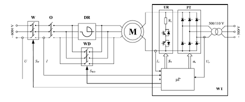
In the circuit of the starting resistor, transistor keys were used in the configuration enabling the flow of bidirectional current induced in the field winding during the asynchronous motor start-up. The contactless excitation system allows to increase the reliability and durability of the device.
The microprocessor system, in addition to controlling the current in the excitation circuit, controls the circuit breakers in the 6 kV field, controlling the permissible working area and the state of internal and external protections located, for example, in the switch bay supplying the motor.
A stand-alone operation mode or cooperation with an external, superior control system is available. Cooperation with external devices is carried out through built-in RS-485, USB and Ethernet communication interfaces. Suitable firmware versions enable the device to work with a medium voltage inverter in the synchronous motor stator circuit or control the voltage of the synchronous generator.
Free retardation braking
Figure 2 shows the registered course of the rotational speed of the drive system during free retardation of the synchronous motor. The motor was switched off while running at a synchronous speed, and the braking time was 15 minutes and 26 seconds. The shutdown consisted of opening the stator power switch and quickly discharging the energy of the field circuit by preparing the thyristor bridge to inverter-type work [3].

The motion equation for the rotating element is as follows

where: J – moment of inertia, M – moment affecting the drive system, ω – angular speed.
During the braking process, the load torque M has a negative sign. For an unloaded motor coast, this moment is the sum of the friction torque Mf and the moment of ventilation resistance Mv:

where kv – a constant reflecting the influence of rotational speed on the value of the moment of ventilation resistance, hence the equation of motion can be written as

and after differentiation, the expression is given for the angular velocity as a function of time

After the braking time th the speed ω is 0 (slip s=1), i.e.:

Knowing the braking time th, the moment of inertia J can be expressed in the following form

and including in (4) the following is obtained

simplifying the entry as
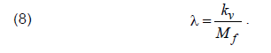
Equation (7) describes the curve passing through the point A(t=0, s=0) and B(t=th, s=1) of the waveform in Figure 2 (where s – slip corresponding to the speed of rotation) however, such curves are infinitely many depending on the coefficient λ. To determine the coefficient λ, the knowledge of the additional point of ω=f(t) characteristic is required.
Assuming the coordinates of the point C(t=5, s=0.6) for the motor speed curve from Figure 2, the value of the coefficient λ was determined by a numerical method as λ=1.181·10-3 s2, which allows the expression of the curve shape of the braking using the analytical equation without the knowledge of the values of the moment of inertia of the drive system and the moment of friction and ventilation losses.
Equation of the synchronous machine motion
The mathematical model of a salient-pole synchronous machine, due to the magnetic asymmetry of the rotor, is usually presented in the form of a system of equations describing currents, voltages and fluxes expressed in relative units in a d-q system rotating at synchronous speed, supplemented by a motion equation in the following form

where: TM – mechanical time constant, ψd, ψq – relative rotor magnetic flux linkages in d and q axis, id, iq – relative stator currents in d and q axis, m0 – relative load torque. According to the presented standard mathematical model, with the stator windings open (id=0, iq=0), the braking torque is equal to the moment of load m0, in which the moment of friction and the moment of ventilation losses can be taken into account.
The spinning rotor of a synchronous machine with forced field current generates a magnetic field permeating the stator’s static structure. The magnetic flux, which is variable in the time and space generates loses in the iron, which can be divided into hysteresis losses and eddy-current losses.
Hysteresis losses over one period are proportional to the hysteresis loop area, and are proportional to the frequency of re-magnetization of the iron. For a synchronous machine with forced current flow into the excitation winding, this frequency is related to the rotor speed.
Eddy-current losses are associated with the induction of iron currents due to the changing magnetic field. With sinusoidal flux variability, based on empirical studies by Richter, they are assumed to be proportional to the square of the frequency of changes in the magnetic field.
In a rotating synchronous machine with open armature winding and forced flow of field current, the magnetic flux is greater than the flux in the rated synchronous operating state due to the lack of reaction of the magneto-motive force of the armature, which causes a much greater impact of eddy-currents on the braking torque than in the synchronous state, not included in the standard mathematical model of the synchronous motor.
Braking the motor by field current
Increasing the effectiveness of the motor braking process is possible thanks to the induction of eddy-currents in the stator magnetic circuit due to the flow of current in the rotating field winding.
The general theory of eddy currents is known, and research on eddy-current brakes has been carried out for over 100 years [4-7], using more and more modern techniques recently, e.g. by means of finite element analysis [8, 9]. The main problem in this type of research is the proper determination of the model parameters and the need to adopt some simplifying assumptions.

The presented method does not require knowledge of the system parameters, and is based on the observation of the course of the rotational speed change during the motor braking process. In addition, it does not require the use of additional braking devices, using the phenomena caused by the flow of current in the rotating field winding with open stator windings.
Figure 3 shows the recorded waveforms during the deceleration process of the tested motor for different values of the field current. For field current If1=150 A, the overrun time has been reduced to 8 minutes 55 seconds and for field current If2=345 A to 3 minutes 12 seconds.
Assuming that the hysteresis losses are proportional to the speed of the magnetic field’s rotation generated by the field current, and the eddy-current losses are proportional to the square of this speed, the motion equation can be represented as
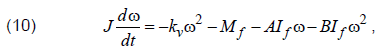
where: A, B – constants with unknown values. Differentializing (10) gives an equation describing the angular speed ω as a function of the field current If and coefficients A and B, and additionally it is difficult to determine the friction torque Mf on the basis of the speed during the coasting, which makes it impossible to determine the numerical values of the unknowns even when knowing additional points of registered speed curve.
There are methods to determine the mechanical losses of the drive system [10-12], but they require measurement of other quantities, e.g. power at the moment when the braking procedure starts.
Assuming that the additional braking moment related with the magnetic field from the field current depends on the rotational speed of the rotor and the rotational speed during the braking process depends on time, a correcting element has been introduced into (7), obtaining a dependence in the following form

where C and D are unknown constants, and the t/th member takes into account the influence of speed on the additional braking torque related to the current flow in the field circuit.
For the excitation current If1, the rotational speed ω reaches the value 0 after the braking time th1, which considering in (11) allows to save the coefficient C in the following form

Equation (12) means that there are infinitely many coefficients C and D that provide the solution.
Taking into account the braking time of the th2 engine with the If2 excitation current, the numerical value of the D coefficient can be determined

and next, coefficient C from (12) can be determined too. For the tested drive system these values were determined as C=2.462·10-4 s-1A-D and D=2.333.
The determined coefficients reflect the influence of various phenomena, such as losses on hysteresis and eddy-currents loses, magnetic circuit nonlinearity, parasitic moments and other phenomena difficult to describe in an analytical manner and requiring the adoption of many simplifying assumptions.
Taking into account the determined coefficients C and D in (11), it is possible to determine analytically the field current causing the motor to stop after a given time tx

Based on (14), the dependence of the braking time on the field current shown in Figure 4 was determined.

Determining the time after which the motor will stop at the given field current, due to the entanglement of time t in (14), is possible only through a numerical calculation process. For the assumed field current If3=400 A, based on (14), the engine stoppage time was determined as 2 minutes 31 seconds. Figure 5 shows the registered motor speed during braking process in such a case. The real braking time was 2 minutes 23 seconds.

Conclusions
Using the braking moments generated from the eddy-currents in the machine body generated by the flow of current in the rotating field winding of the rotor, the motor braking time can be significantly reduced without the use of additional braking devices. It is also possible to quite accurately estimate the field current causing the drive to stop within the set time without knowing the magnetic and mechanical parameters of the system. The presented method of determining the influence of the field current on the course of the synchronous motor braking process does not require knowledge of the motor parameters, and at the same time allows to take into account the influence of real phenomena in the motor stator magnetic circuit, which are associated with the interaction of the rotating magnetic field generated by the current in the field winding.
The considerations concerned the coasting and braking of the synchronous motor non-loaded by the braking torque of driven device. The braking torque of the driven device causes the motor to stop in an even shorter time, but regardless of this, the maximum reduction of the braking time will be achieved at the maximum permissible field current. But it should be taken into account that the current flow through the field winding causes losses in this winding, resulting in an increase of its temperature , simultaneously the reduction of the speed of rotation causes the ventilation and cooling of the winding to become less effective.
The tests carried out with the motor and the microprocessor block for excitation [2] confirmed the possibility of controlling the motor braking time with the help of the field current. The application of the field current control system regardless of the state of the motor operation makes the braking procedure effective even after an emergency power off and opening of the stator windings.
REFERENCES
[1] Decree by the Minister of Economy from 28 June 2002 on occupational health and safety, mining operations and fire protection in underground mines, Republic of Poland Journal of Law from 2002, No 139, item 116 9 and from 2006, No 124, item 863
[2] Hyla M.: Power supply unit for the excitation of a synchronous motor with a reactive power regulator, Mining – Informatics, Automation and Electrical Engineering, vol. 53, no. 1, pp. 17-21, 2015
[3] Hyla M.: Wybrane aspekty sterowania tyrystorową wzbudnicą silnika synchronicznego (in Polish, abstract in English), 5th Conf. Modelling and Simulation, Kościelisko, 2008, pp. 345–348
[4] Morris D. K., Lister G. A.: The eddy current brake for testing motors, Journal of the Institution of Electrical Engineers, vol.35, no. 175, pp. 445-468, 1905
[5] Davies E. J.: General theory of eddy-current couplings and brakes, Proceedings of the Institution of Electrical Engineers, vol. 113, no. 5, pp. 825-837, 1966
[6] Gonen D., Stricker S.: Analysis of an Eddy-Current Brake, IEEE Transactions on Power Apparatus and Systems, vol. 84, no. 5, pp. 357-361, 1965
[7] Venkataratnam K., Kadir M. S. A.: Normalized Force-Speed Curves of Eddy Current Brakes with Ferromagnetic Loss Drums, IEEE Transactions on Power Apparatus and Systems, vol. PAS-104, no. 7, pp. 1789-1796, 1985
[8] Holtmann C., Rinderknecht F., Friedrich H. E.: Simplified model of eddy current brakes and its use for optimization, 10th Int. Conference on Ecological Vehicles and Renewable Energies (EVER), Monte Carlo, 2015, pp. 1-8
[9] Sinmaz A., Gulbahce M. O., Kocabas D. A.: Design and finite element analysis of a radial-flux salient-pole eddy current brake, 9th Int. Conf. on Electrical and Electronics Engineering (ELECO), Bursa, 2015, pp. 590-594
[10] Ilina I. D.: Experimental determination of moment to inertia and mechanical losses vs. speed, in electrical machines, 7th Int. Symposium on Advanced Topics in Electrical Engineering (ATEE), Bucharest, 2011, pp. 1-4
[11] Ćalasan M., Ostojić M., Petrović D.: The retardation method for bearings loss determination, Int. Symposium on Power Electronics Power Electronics, Electrical Drives, Automation and Motion, Sorrento, 2012, pp. 25-29
[12] Ćalasan M. P., Petrović D. S., Ostojić M. M.: Electrical braking of synchronous generators for combined generator and water turbine bearings as well as stray-load losses determination, IET Electric Power Applications, vol. 7, no. 4, pp. 313-320, 2013
Autor: dr inż. Marian Hyla, Silesian University of Technology, Faculty of Electrical Engineering, Department of Power Electronics, Electrical Drives and Robotics, ul. B. Krzywoustego 2, 44-100 Gliwice, Poland, e-mail: marian.hyla@polsl.pl
Source & Publisher Item Identifier: PRZEGLĄD ELEKTROTECHNICZNY, ISSN 0033-2097, R. 96 NR 11/2020. doi:10.15199/48.2020.11.04
