Published by Konrad URBAŃSKI, Dariusz MAJCHRZAK,Poznań University of Technology
Abstract. In this paper, simulation research results of PMSM drive with open phase fault detection are presented. Proposed fault detection system is implemented using two artificial neural networks. One of them is neural model of healthy PMSM and another one generates diagnostic signals. When the fault occurs, the amplitude of current residuals increases and evaluation system returns diagnosis. In proposed system detection time is about 1 ms. Moreover, diagnosis does not depend on load state.
Streszczenie. Artykuł przedstawia wyniki badań symulacyjnych napędu PMSM z detekcją przerwy fazy. Proponowany system detekcji uszkodzeń zaimplementowano z użyciem dwóch sztucznych sieci neuronowych. Jedna z nich pełni rolę modelu neuronowego sprawnego PMSM, natomiast druga generuje sygnały diagnostyczne. W przypadku wystąpienia uszkodzenia amplituda residuów prądów wzrasta, a system ewaluacji zwraca diagnozę. Czas detekcji w przedstawionym układzie jest rzędu 1 ms. Ponadto działanie systemu nie zależy od stanu obciążenia (Detekcja uszkodzeń w napędzie z PMSM przy użyciu Sztucznej Sieci Neuronowej).
Keywords: Artificial Neural Network, PMSM, Fault detection, Electric drive.
Słowa kluczowe: Sztuczna Sieć Neuronowa, PMSM, Detekcja uszkodzeń, Napęd elektryczny.
Introduction
The permanent magnet synchronous motors (PMSM) are becoming increasingly popular in industry due to their high power density, low inertia and high efficiency. Thanks to their excellent dynamic performance, they are widely used in robots, machine tool, winders and similar systems that require precise speed and torque control. Nowadays, electrical drives often work in human life-critical systems, where high reliability is required [1]. In these applications the traditional control algorithms do not provide a sufficient safety, so fault tolerant control (FTC) is commonly used. FTC algorithms require information about type and location of fault [2], therefore the fault detection and diagnosis systems are necessary. There are many methods of fault detection and identification. They can be divided into signal processing based and model-based categories. First of them uses measured signals analysis methods such as spectral analysis [3] or wavelet transform [4]. In general, they only uses output signals of drive, but no input signals, so influence of input on output may be ignored [5]. Mode-based methods use information about structure and parameters of dynamic model of plant. These include state estimation methods, for example observers or Extended Kalman Filter [6]. Moreover, model parameters estimation methods like recursive last square algorithm can be used [7]. Model-based methods generate residuals, by estimating output signals (or parameters of the plant) and computing estimation error vector [8]. Next the residual evaluation system generates diagnosis. Fig. 1 presents the block diagram of model-based method of fault detection. Symbols shown in Fig. 1 are u – plant inputs, y – plant outputs, z – disturbance, f – fault, and r – generated residuals. The main disadvantage of mentioned methods is the need for a reliable model [5]. In this paper, fault detection method based on model is connected with computational intelligence methods. Presented in this paper the residual generator contains neural model of PMSM. Moreover, the residual evaluation system is also realized using the Artificial Neural Network (ANN).
Mathematical model and control structure
Dynamic model of PMSM used in this paper is given as follows:


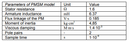
where id, iq,Ld, Lq, vd, vq – currents, inductances and voltages in d-q axes, R – winding resistance, p – pole pairs, ωr – angular speed of rotor, λ – permanent magnets flux linkage, Te – electromagnetic torque, J – moment of inertia, F – viscous friction coefficient, Tm – load torque, ϴ – rotor angular position.
Used control algorithm was Field Oriented Control (FOC) [9]. Clarke and Park transforms were used for 3 phase non-rotating frame into two coordinate rotating reference frame conversions. PI controllers were used in speed and currents control loops. Transistors gate pulses were generated using Space Vector Pulse Width Modulation (SVPWM) [9]. The block diagram of control structure is shown in Fig. 2.

Fault detection method
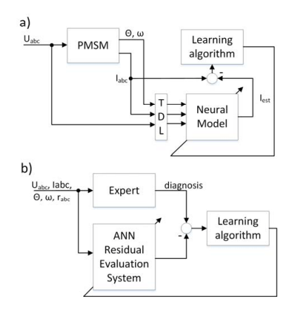
The main blocks of the system are neural model of PMSM and diagnostic module. The inputs of the both networks are phase currents, phase voltages, speed and the motor shaft position. In addition, the current residuals vector is given to the input of the diagnostic block, which returns the diagnosis. The output of the system is diagnostic signal which indicates open phase fault occurrence. The block diagram of the system is presented in Fig. 3.

In the figure, ϴ is the position, and ω is the speed. For increase of residual signal magnitude during open phase fault, in place of measured currents the weighted arithmetic mean of estimated and measured currents was applied. Used coefficients was experimentally determined and was 0.8 for estimated and 0.2 for measured values. The tapped delay line (TDL), delays voltages, speed and position samples by 0, 1 and 2 steps. It also delays currents by 1 and 2 steps. In practical applications the phase voltages are not measured. To avoid implementation of extra sensors the reference voltages can be used. In that approach system processes variables that are already used by vector control algorithm.
Signals acquired from the several simulations of healthy motor drive, working at various speeds and loads were used for training the neural model. Residual evaluation system was trained on data obtained during open phase fault simulations. A fault trigger signals were used as a target data. Neural model consists two-layer feed-forward ANN, with 6 neurons in the first layer, and 3 neurons in output layer. Activation functions are hyperbolic tangent in hidden layer, and linear in output layer. Residual evaluation system is three-layer perceptron. The first hidden layer has 14 and the second 7 neurons. Activation functions are:
linear in the first layer and hyperbolic tangent in the other ones. Both ANNs were trained with the Levenberg Marquardt algorithm [10,11] with Bayesian regularization using structures shown in Fig. 4.
Simulation results
The simulation studies of presented system were performed in MATLAB/Simulink environment. PM machine and power converter models were implemented using SimPowerSystems toolbox. The PMSM drive model operates using vector control, with outer loop of speed control, and inner loop of current control. The motor is fed by a voltage source inverter. It was necessary to create power converter in such a way that the open phase fault could be simulated. There was logical AND operation applied on transistors gate pulse signals, to simulate open circuit fault by holding selected ones at logical zero. The ANNs were implemented and trained using MATLAB Neural Networks Toolbox. Fundamental sample time used in simulation was 1 μs for motor and power converter models, and 100 μs for other blocks. The PWM carrier frequency was equal 10 kHz, and used “dead time” was equal 4 μs. Some sample simulation results of fault detection system behavior are shown in Fig. 5. and Fig. 6.
The waveforms in Fig. 5a shows phase currents during motor startup, which is working at speed 250 rad/s. In addition, at time 0.04 s, a stepwise load was attached, from zero to nominal value. At time 0.06 s open phase A fault is occurred. It is shown in Fig. 5b that fault occurrence causes residuals amplitude increase. This is because of differences between measured and estimated currents. There are some peaks in residual evaluation system output signal, as presented in Fig. 6a. It is caused by inaccurate model of electric drive. To avoid a false-positive error the 10 point moving average filter was applied. Proposed filter was defined as:


where ff – filter output signal , fraw – filter input signal, and N – number of points in average. The figure 6b presents filtered residual evaluation system output signal. Diagnosis is created by thresholding of filtered signal.
In the Fig. 7 the impact of the time-varying load torque on diagnosis is presented. After motor startup, drive is working at constant speed and load torque steps and ramps occur.
It can be seen, that peaks in residual evaluation system output signal has been filtered and diagnosis does not depend on load state. It is worth noting that fault detection system works properly from the very beginning of motor startup, so no detection disabling signals are required. Presented system can work as autonomous block in the motor drive.
Simulations at various speeds and angles has been done to examine the electrical angle of the fault occurrence impact on detection time. In table 1, there are presented the fault detection times in a case of various conditions for testing of the break in phase A.
Table 1. Detection time at different electrical angle of open phase A fault occurrence and at various speeds

In the most cases, detection time is less than 1 ms, except angles near 0° and 180° during phase A current zero crossing. Zero phase current caused by open phase fault cannot be distinguished from natural current zero crossing so fault detection is delayed. It is worth to add that angular velocity does not impact on detection time.
Conclusions
In this paper, an open phase fault detection system has been introduced. Presented method was verified by simulation research and gave good results. Proposed detection system is fast – detection time is about 1 ms. Short time of fault detection allows to enable FTC algorithm before eventual drive damage, which may occur due to high torque pulsation during open phase state. Presented system processes variables which are already used by vector control algorithm, avoiding the use of extra sensors. Moreover, transient states of drive system and motor speed do not influence diagnosis.
Appendix. Parameters of used Permanent Magnet Machine model
REFERENCES
[1] Ertugrul N., Soong W., Dostal G., Saxon D., Faulttolerant motor drive system with redundancy for critical applications, proceedings of the IEEE Power Electronics Specialists Conference 2002 (PESC ‘02), pp. 1457-1462, 2002.
[2] Łuczak D., Siembab K., Comparison of fault tolerant control algorithm using space vector modulation of PMSM drive, proceedings of the 16th Mechatronika, pp. 24-31, 2014.
[3] Khlaief A., Boussak M., Gossa M., Phase faults detection in PMSM drives based on current signature analysis, XIX International Conference on Electrical Machines (ICEM), pp. 1-8, 2010.
[4] Riba J.R., Rosero J.A., Garcia A., Romeral L., Detection of demagnetization faults in permanent-magnet
synchronous motors under nonstationary conditions, IEEE Transactions on Magnetics, vol 45, no. 7, pp. 2961-2969, 2009.
[5] Liu X.Q., Zhang H.Y., Liu J., Yang J., Fault Detection and Diagnosis of Permanent Magnet DC Motor Based on Parameter Estimation and Neural Network, IEEE Transactions on Industrial Electronics, vol 47, no. 5, pp.1021-1030, 2000.
[6] Park B.G., Jang J.S., Kim T.S., Hyun D.S., EKF based fault diagnosis for open-phase faults of PMSM driver, proceedings of the IEEE In Power Electronics and Motion Control Conference, pp. 418-422, 2009.
[7] Park B.G., Kim R.Y., Hyun D.S., Fault diagnosis using recursive least square algorithm for permanent magnet synchronous motor drives, in Power Electronics and ECCE Asia (ICPE & ECCE), pp. 2506-2510, 2011.
[8] Korbicz J., Koscielny J.M., Kowalczuk Z., Cholewa W., Fault Diagnosis. Models, Artificial Intelligence, Applications, Springer ,Berlin 2004.
[9] Quang N.P., Dittrich J.-A., Vector Control of ThreePhase AC Machines, Springer, Berlin 2008.
[10] Levenberg K., A Method for the Solution of Certain Non-Linear Problems in Least Squares. Quarterly of Applied Mathematics 2, pp. 164–168, 1944.
[11] Marquardt D., An Algorithm for Least-Squares Estimation of Nonlinear Parameters. SIAM Journal on Applied Mathematics 11 (2), pp. 431–441, 1963.
Authors: dr inż. Konrad Urbański, Politechnika Poznańska, Instytut Automatyki i Inżynierii Informatycznej, ul. Piotrowo 3a, 60-965 Poznań, E-mail: Konrad.Urbanski@put.poznan.pl; mgr inż. Dariusz Majchrzak, Automatyki i Inżynierii Informatycznej, ul. Piotrowo 3a, 60-965 Poznań, E-mail: Dariusz.zb.Majchrzak@doctorate.put.poznan.pl.
Source & Publisher Item Identifier: PRZEGLĄD ELEKTROTECHNICZNY, ISSN 0033-2097, R. 93 NR 6/2017. doi:10.15199/48.2017.06.06
