Published by Aleksander JAKUBOWSKI1, Natalia KARKOSIŃSKA–BRZOZOWSKA2, Krzysztof KARWOWSKI1, Andrzej WILK1, Gdańsk University of Technology, Faculty of Electrical and Control Engineering (1), Civil and Environmental Engineering (2)
Abstract. The paper presents possible environmental, energy and economical gains implied by replacing conventional traction vehicles with independently powered electric multiple units (IPEMU) on partially electrified suburban railways. IPEMUs can operate in two modes of power supply – using an overhead catenary or the on–board battery storage. Appropriate computer simulations were carried out in the Matlab program, indicating the parameters of storage electric multiple units.
Streszczenie. W artykule wskazano na potencjalne korzyści energetyczne, środowiskowe i częściowo ekonomiczne wynikające z zastąpienia konwencjonalnych jednostek trakcyjnych nowymi zasobnikowymi zespołami elektrycznymi mogącymi się poruszać na liniach kolejowych częściowo niezelektryfikowanych. Zespoły te mogą pracować w dwóch trybach – zasilania sieciowego lub zasobnikowego. Przeprowadzono odpowiednie symulacje komputerowe w programie Matlab wskazując na parametry zasobnikowych zespołów trakcyjnych. Zasobnikowe zespoły trakcyjne w transporcie podmiejskim
Keywords: railway electric traction, vehicle hybrid power, energy storage devices, computer simulation.
Słowa kluczowe: elektryczne pojazdy szynowe, hybrydowe zasilanie pojazdu, zasobniki energii, symulacja komputerowa.
Introduction
Improved versions of electric rail vehicles have been implemented for over 100 years, capable of crossing routes on non–electrified railway sections. The AT 3 series of two– car electric battery traction unit, known as Wittfeld after the name of the designer, eng. Gustav Wittfeld [1] is an interesting vehicle from the beginning of the 20th century. The train, which could seat 90 passengers, was powered by two 62 kW motors and reached speeds of up to 60 km/h with a tare weight of 60 t. In Gdańsk Pomerania region, AT 3 units most often serviced suburban traffic. Subsequent modernizations extended the range of the units up to 300 km. In the 1950s, worn–out battery rail–cars were withdrawn from line use in Poland.
Current global trends point to potential energy, environmental and partly economic benefits resulting from the replacement of conventional DMU (Diesel Multiple Unit) traction units with new BEMU (Battery Electric Multiple Unit) electric vehicles, and especially IPEMU (Independently Powered Electric Multiple Unit) that can run on partially non–electrified lines [2–8]. DMU and BEMU vehicles are operated on non–electrified lines. IPEMU vehicles can work in two modes – overhead contact line or storage supply. On electrified sections, these assemblies draw energy from the overhead contact line for vehicle propulsion, non–traction needs and energy storage charging, while on non– electrified sections they consume energy from the accumulator, which is recharged during regenerative braking. As energy storage, Li–ion batteries are used most often, and sometimes as a hybrid storage in combination with supercapacitors [9, 10]. Vehicle power systems based on fuel cells and hybrid storages are also considered in the literature [2].
An example of the Tri–City (Gdańsk–Sopot–Gdynia) agglomeration railway line was selected for the sake of analysis and simulations presented below. A short 8– kilometer section of the single–track passenger line on the Gdynia Chylonia – Gdynia Port Oksywie route was considered, on which revitalization is planned that could reduce heavy traffic at rush hours (Fig. 1). On–board battery storage of IPEMU units charged from the catenary line while traveling on the Gdynia Główna – Gdynia Chylonia section of the Urban Rapid Railway (pol. Szybka Kolej Miejska, SKM) line would allow for further travel to the Port Oksywie station and return travel without the need to build electrical traction infrastructure [11].

In the Tri–City agglomeration you can find many sections of the line with similar features as, for example, regional line No. 213 Reda – Hel with a length of 62 km with great touristic importance. The IPEMU unit can be supplied from the catenary line on the Gdynia Główna – Reda section, which is enough to travel from Reda to Hel station. To charge the vehicle before the return trip, a charging station was assumed to be built to charge the unit while stationary. Similar railways can also be found in other national agglomerations.
Electrical drivetrain structure
Virtually all electric multiple units (EMUs) built nowadays use an overhead contact line or a third rail for power supply. Vehicles operating in urban rail networks in Poland utilize DC line voltage of 3000 V. Thus, the construction and maintenance of a costly railway electrification system is necessary. However, depending on localization, unobstructed construction works may be impossible. The impact of electric catenary on the environment needs also to be taken into account.
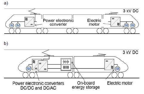
Electric multiple units are characterized by drivetrain spread over all carriages, with numerous induction motors, installed in pairs in motorized bogies and fed by inverters (Fig. 2a). Such design allows for wide–range tractive effort regulation with good dynamics and regenerative braking.
Therefore, equipping EMU with on–board energy storage (Fig. 2b) that allows to travel through non– electrified route sections might be worthwhile. Such solutions were implemented in trolleybuses and are widely used [12].
Fundamental drawbacks for using energy storages in railway vehicles are the large size and weight of such devices, and the necessity of additional energy converter usage. In comparison to a vehicle supplied by an overhead line, IPEMU could have limited passenger space and slightly worse energy efficiency. Therefore, onboard storage applications are limited to light rail vehicles with various drivetrain design.
Vehicle model
Energy consumption analysis of rail vehicle equipped with on–board battery storage has been conducted on the basis of train run calculations [13–15]. For this task, a simulation program was developed using Matlab/Simulink software. Thanks to modular structure of the program, editing input parameters can be easily done, allowing for multiple cases analysis (Fig. 3).

Calculations are based on vehicle movement dynamics model, described by equation

where: a – acceleration, v – velocity, s – distance, z – control function, F – tractive effort, W – motion resistance, m – vehicle mass, k – rotational mass coefficient.
which is calculated by integrating acceleration a(t). Tractive effort F is set by control function z(s, v, t), with output limited to the range determined by rated torque and speed of the electric drivetrain. Motion resistance W(v,s) consists of fundamental Wz(v) and additional Wd(s) components – the former represents air drag, friction forces and rolling resistances (dependent on velocity), the latter reflects resistance forces from railroad track geometry curvature and inclination.
It was assumed, that acceleration and braking are realized with full available tractive effort; to simplify calculations, electric–only braking was considered. The velocity profile was set by control function z(s, v, t) which determines the relation between cruising and coasting phase, acceleration/braking dynamics as well as station stationary time. The control function program has been designed with compatibility with various drivetrain models and optimizing algorithms in mind.
Electrical energy usage is calculated by integrating electrical power, which is equal to mechanical power (computed by multiplication of traction effort and movement velocity) divided by drivetrain efficiency factor

where: Ez – energy consumed, η – drivetrain efficiency factor, pn – power of auxiliary loads, T – analyzed run time.
In order to estimate more accurately the energy consumption, a changing efficiency value of η(F, v) was adopted, using a predetermined table expressing the dependence of the propulsion efficiency on the torque produced by the engines and their angular velocity. The value of the power of the vehicle’s own needs has been defined at a constant level.
Energy recuperated during electric braking of the analyzed vehicle is computed as

Onboard battery storage has been represented by a battery model, defined in Simscape/SimPowerSystems library. Its capacity was calculated in order to allow the vehicle to cover the analyzed route in both directions, without using an overhead line nor charging the battery underway. A fully charged state of batteries at the beginning of non–electrified route was assumed.
Energy requirement for IPEMU on the analyzed railway line
Initial run calculations were conducted for 2 MW, 4– section electric multiple unit (Fig. 2a), which is a standard formation for trains in urban rail operating in Poland.
Hypothetically, such conventional vehicle could have on–board battery storage installed, so it can operate on local non–electrified line between stations Gdynia Chylonia and Gdynia Port Oksywie (15,7 km round trip, station numbers – Fig. 1). The route is characterized by relatively small differences in elevation and the speed limit is set at 70 km/h for most of its length. Entire drivetrain parameters utilization was assumed, so acceleration and braking were realized with maximum available tractive effort, also distance between stations was covered with maximum speed allowed (without coasting). The computed speed waveform is shown in Fig. 4a.
Maintaining desired velocity profile requires adequate power supply, which needs to be provided by on–board battery storage. Thus, values of battery capacity and maximum continuous discharge current are the critical factors in storage design (Fig. 4b).
On–board battery storage with parameters allowing conventional EMU for operation under assumed conditions would mass about 18 t. The volume of the storage is also significant – almost 20 m3. Equipping a vehicle with such a massive device would be impractical.

For further analysis, based on 2– section DMU similar to Pesa SA132–class (produced by PESA Bydgoszcz SA), a light rail vehicle was considered. The hypothetical vehicle would be powered by two 350 kW induction motors, sufficient for maximum speed of 100 km/h. Assuming that electric motors with inverters would replace diesel engines with torque converters and fuel tanks, 80 t net weight of vehicle was increased by 10 t (estimated weight of Li–ion battery storage).
Calculations were performed for two velocity profiles – trapezoidal, without coasting (Fig. 5) and energy–efficient (coasting until braking zone or speed dropping below 60 km/h, Fig. 6).
Results of the storage operation simulation are shown in Fig. 7. At the end of the analyzed run, the state of charge dropped to 78% – batteries were under no risk of deep discharge despite the fact that the storage was not recharged underway. Therefore, the assumed battery storage parameters are sufficient for a vehicle to cover the analyzed route without motion dynamics limitations. Also, there is no need for charging station construction. It is worth noting, that the size of battery storage could be reduced while prolonging its lifespan by equipping supercapacitors, which would absorb regenerative braking energy and provide additional power during acceleration.
Application study and investment costs
In existing Japanese [19] and British IPEMU applications, two–segment lightweight vehicles with a mass of approx. 40 t, number of passengers 130, maximum speed of 100 km/h and acceleration of 1.2 m/s2 were adopted on agglomeration lines. An interesting European vehicle offer is the Bombardier Talent 3 intended for German and Austrian railways with much higher parameters – necessary rather for regional transport (3 units, 140 km/h, 170 seats) [20].


According to the manufacturer, Talent 3 generates noise and vibrations level 7 dB lower than DMU vehicles, does not emit NOx and indirectly generates CO2 only in power plants. The installed energy storage increases the vehicle’s energy efficiency compared to classic EMUs as a result of braking energy recovery and starting support. To compare the costs of purchasing Talent 3, the prices of domestic producers’ delivery were analyzed as part of tenders from 2016 for EMU and DMU vehicles for the Wielkopolskie, Śląskie, Mazowieckie and Przewozy Regionalne railway companies as well as for Poznań Metropolitan Railway. The average purchase costs are summarized in Table 1. In lines 2 and 3, there are approximate values which, together with the lack of electrification cost of the sample line (line 4) indicate the advantages of IPEMU. The full analysis of the legitimacy of choosing the type of traction unit should include the cost of the entire Life Cycle Cost, which for IPEMU is still difficult to determine.
Summary
The simulation analyses carried out indicate that on both urban and suburban lines it may be beneficial to introduce electric storage traction units of the IPEMU type to service passengers. Estimated costs presented in Tab. 1 indicate the profitability of purchasing one IPEMU instead of classic DMU while discarding 8 km section electrification. The purchase of a classic electric multiple unit together with the electrification of the section in question is similar in price to IPEMU without catenary line. However, the purchase of a larger number of IPEMUs can be economically justified if they are also used to support other non–electrified sections, e.g. Gdańsk Wrzeszcz – Airport, Rumia – Hel and similar. This relation of investment costs can be a challenge for domestic rail vehicle manufacturers in the construction of light IPEMU with technical parameters sufficient to operate on both urban and suburban lines.
Table.1 Average costs of purchase, transport and CO2 emissions of trainsets in Polish national conditions DMU
REFERENCES
[1] Jerczyński M., Nasz portret: wagon akumulatorowy typu„Wittfeld”, Świat Kolei 03 (1995)
[2] Pagenkopf J., Kaimer S.: Potentials of alternative propulsion systems for railway vehicles – a techno–economic evaluation, Ninth International Conference EVER, 2014
[3] Ghaviha N., Bohlin M., Holmberg C., Dahlquist E., Speed profile optimization of catenary–free electric trains with lithium–ion batteries, Journal of Modern Transportation, 2019
[4] Furuta R., Kawasaki J., Kondo K., Hybrid traction technologies with energy storage devices for nonelectrified railway lines, IEEJ Transactions on Electrical and Electronic Engineering, Vol. 5, Issue 3, 2010, 291–297
[5] H. al–Ezee, C. Gould, S. B. Tennakoon, Novel method for energy management for catenary free system operation, 53rd International Universities Power Engineering Conference, 2018
[6] Y. Kono, N. Shiraki, H. Yokoyama, R. Furuta, Catenary and storage battery hybrid system for electric railcar series EV–E301, International Power Electronics Conference, IPEC, 2014
[7] Shao–bo Yin, Li–jun Diao, Wei–jie Li, Rong–jia He, Hai–chen Lv, On board energy storage and control for inter–city hybrid EMU. 43rd Annual Conference, IECON 2017
[8] F. Becker, A. Dämmig, Catenary free operation of light rail vehicles – topology and operational concept. 18th European Conference EPE’16 ECCE Europe, 2016
[9] Long Cheng, Wei Wang, Shaoyuan Wei, Hongtao Lin, Zhidong Jia, An improved energy management strategy for hybrid energy storage system in light rail vehicles, Energies 2018
[10] Radu P. V., Szelag A., Steczek M., On–Board energy storage devices with supercapacitors for metro trains – case study analysis of application effectiveness. Energies, 2019, 12, 1291
[11] Telecki M., Studium zastosowania zasobnikowych elektrycznych jednostek trakcyjnych na tworzonej pasażerskiej linii kolejowej do północnych dzielnic Gdyni. Praca dyplomowa. Politechnika Gdańska, 2018
[12] Bartłomiejczyk M., Dynamic charging of electric buses. De Gruyter, 2019
[13] Karwowski K. (red.), Energetyka transportu zelektryfikowanego. Poradnik inżyniera. Wyd. Politechniki Gdańskiej, Gdańsk 2018
[14] Bartłomiejczyk M., Mirchevski S., Jarzębowicz L., Karwowski K., How to choose drive’s rated power in electrified urban transport? 17th European Conference, EPE’17 ECCE Europe, 2017
[15] Jakubowski A., Jarzębowicz L., Karwowski K., Wilk A., Efektywność energetyczna pojazdu szynowego w różnych warunkach obciążenia, TTS Technika Transportu Szynowego, 12 (2018), 44–48
[19] Takiguchi H., Overview of series EV–E301 catenary and battery–powered hybrid railcar, JR EAST Technical Review No. 31 (2015) 27–31
[20] Laperrière P., Realize your vision with Bombardier TALENT 3 BEMU, APTA Rail Conference, 2019
Authors: mgr inż. Aleksander Jakubowski, Politechnika Gdańska, Wydział Elektrotechniki i Automatyki E-mail: aleksander.jakubowski@pg.edu.pl; mgr inż. Natalia Karkosińska– Brzozowska, Politechnika Gdańska, Wydział Inżynierii Lądowej i Środowiska, E-mail: natalia.brzozowska@pg.edu.pl; dr hab. inż. Krzysztof Karwowski, E-mail: krzysztof.karwowski@pg.edu.pl; dr hab. inż. Andrzej Wilk, E-mail: andrzej.wilk@pg.edu.pl; Politechnika Gdańska, Wydział Elektrotechniki i Automatyki, ul. Narutowicza 11/12, 80–233 Gdańsk
Source & Publisher Item Identifier: PRZEGLĄD ELEKTROTECHNICZNY, ISSN 0033-2097, R. 96 NR 4/2020. doi:10.15199/48.2020.04.33
