Published by Marian HYLA, Silesian University of Technology, Department of Power Electronics, Electrical Drives and Robotics
Abstract. The paper presents the concept, implementation and operational effects of the multi-servers automatic reactive power compensation system in 6 kV industry electrical power grid. As controlled reactive power compensators were used synchronous motors, capacitors’ banks and passive filters of higher harmonics available in the power grid of the plant. System of communication and collaboration of control servers with databases was disclosed. Use of events technology of Firebird database was discussed. Clients’ application for industry grid state and compensation system monitoring were presented. Results of operation and planned modernization of the system was presented.
Streszczenie. W artykule przedstawiono koncepcję, realizację praktyczną oraz efekty działania wieloserwerowego systemu automatycznej kompensacji mocy biernej w przemysłowej sieci elektroenergetycznej 6 kV. Jako kompensatory mocy biernej wykorzystane zostały silniki synchroniczne, baterie kondensatorów i pasywne filtry wyższych harmonicznych pracujące w zakładzie. Przedstawiono system informatyczny i współpracę z bazą danych. Omówiono wykorzystanie technologii zdarzeń bazy danych Firebird w prezentowany rozwiązaniu. Przedstawiono oprogramowanie klienckie wykorzystywane do monitorowania pracy systemu i stanu sieci elektroenergetycznej. Przedstawiono przykładowe efekty działania oraz propozycje dalszych prac związanych z modernizacją systemu. (Wieloserwerowy system automatycznej kompensacji mocy biernej z bazą danych Firebird)
Keywords: reactive power compensation, power factor correction, automatic control, data bases, Firebird events technology, monitoring
Słowa kluczowe: kompensacja mocy biernej, współczynnik mocy, automatyczna regulacja, baza danych, technologia zdarzeń bazy Firebird, monitorowanie
Introduction
Reactive power compensation is aimed to relieve an electrical grid of reactive currents flow, what is achieved by elimination the phase shift between the fundamental voltage and current harmonics and by elimination of higher harmonics in the load current regardless of the form of the supply voltage [1, 2]. In such conditions minimizing current and apparent power of the source for a given active power of the load is achieved. In practice, there are many definitions of reactive power [3, 4, 5]. In many industrial electrical grids, is applied a partial compensation, based on the fundamental voltage and current harmonics compensation to maintain a power factor value within the desired range. For this purpose, as a source of reactive power are used capacitors, harmonics passive filters and synchronous compensators both in the form of unloaded and underloaded synchronous motors or generators [4, 6, 7, 8, 9, 10]. Passive harmonic filters used for eliminating selected harmonics are also sources of reactive power of the fundamental harmonic and can be used for tgφ factor correction.
Failure to comply with the relevant technical parameters of the power consumed by customers at points of connection to the supplying power grid causes in additional fees charged by electricity suppliers. To reduce the costs of electricity reactive power consumed from the supply grid at each of the supply points of the plant should be compensated.
The technical benefits effecting from the reactive power compensation are [1, 6, 11, 12, 13, 14, 15]:
• increasing the possibility of active power flows at the same nominal current of power lines or the same active power flows at reduced line current,
• improving voltage conditions of the grid by reducing the voltage drops,
• reducing energy losses caused by reactive current flows,
• reducing equipment failures by limiting the voltage variations in the grid,
• improving power supply reservation conditions and reliability.
The economic benefits of reactive power compensation are [11, 16]:
• reducing fees for active energy consumed to cover transmission of reactive power losses,
• eliminating extra fees charged for non-optimal reactive power consumption: consumption of electric energy with tgφ factor higher than specified in the contract, consumption of inductive reactive energy without active energy consumption and consumption of active energy with capacitive power factor.
At varying active and reactive power consumption caused by a plant production cycle, the solution is automatic, real-time, follow-up reactive power compensation system, allowing independent compensation of each supply point. For this purpose reactive power sources available in the internal power grid are used.
Concept of the automatic reactive power compensation system
Concept of the automatic reactive power compensation system is shown in Figure 1. The task of the compensation system are active and reactive power measuring in supply points of the plant, identification of the actual grid configuration and proper reactive power distribution to the individual, currently available, adjustable sources of reactive power. This task is performed by the main controller.
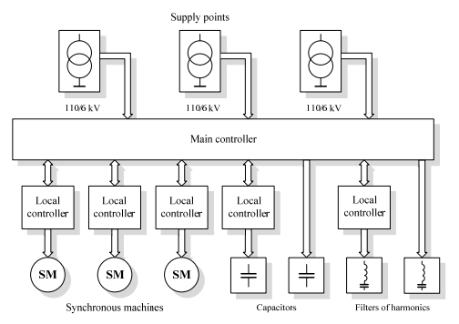
Synchronous machines local controllers are designed to supply given reactive power ensuring proper operation of the drive in the synchronous state [17]. Synchronous operation state is required by superior function of the drive system. Described implementation uses the ProgressPOWER microprocessor-controlled power supply units for the excitation of synchronous motor [18]. This device was developed in co-operation with the author.
Local controllers for switching capacitor banks and filters of harmonics are parts of communication system. Control of capacitor banks matched with control of synchronous compensators realized properly by the main controller holds the power factor in the desired range [19]. Long term variations of reactive power caused by a plant production cycle are compensated by switching the appropriate sections of capacitors. Underloaded synchronous machines in the system of compensation allow step less (continuous) reactive power regulation. They are used for reactive power momentary fluctuations compensation [2, 10, 18, 19, 20].
The adjustable value is power factor tgφ expressed by the equation:

where: P – active power, Q – reactive power. The control algorithm based on measurements at the supply point of the plant determines the actual demand for change of reactive power of the supply transformer according to the equation:

where: ΔQz – required change of reactive power in the actual step of the regulation process, P, Q – the actual active and reactive power at the supply point, tgφz – required power factor at the power supply point of the plant.
Reactive power which should be generated by n available compensators is expressed by the relation:
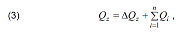
where: Qi – actual reactive power of i-compensator.
The problem of the reactive power optimization with additional criteria and restrictions in multilevel industry grid based on presented solution is analysed in [22]. Calculation algorithm aim to fulfill equation (3) ensuring power factor at the supply point of the plant at the required range.
To enable the independent automatic compensation of each supply point the actual grid configuration should be known by the main controller. Figure 2 shows a part of the grid identified by one of the main controllers of described implementation.
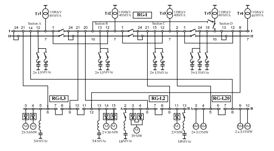
Identified are states of switches and disconnectors in each of the fields of the switching stations shown in Figure 2. This allows to match supplying transformers with each compensator. There are measured electrical parameters in each of the 110/6 kV power supply transformer and thyristor hoisting machines current. Measurement of hoisting machines current is to determine whether the machine operates, what requires switching on the appropriate filters of harmonics. There are also available measurements of synchronous drives, transmitted to the main controller by the local controllers of the synchronous machines. The state of the grid and measurements are stored in the database, enabling later system operation analysis.
Informatics structure
The presented idea of the automatic reactive power compensation system has been implemented in a large mining plant in Poland. A characteristic features of the plant grid are a considerable distance between the supply switching stations of the plant up to several km and the fact that separate parts of the grid are supplied independently.
In Poland energy costs for industrial plants are calculated separately for each power supply point. For this reason it was decided to use multi-servers system which allows autonomous operation at each location, and at the same time it is prepared to work in the event of payment calculation change e.g. fees calculation based on groups of power suppling points or even for the entire plant.
Figure 3 shows the informatics structure of the realized multi-servers reactive power compensation system. Control servers perform functions of main controllers as shown in Figure 2. Each control server is responsible for the independent part of the grid and cooperates with its own database.
The described system consists of:
• 4 control servers and 4 databases,
• 9 switching stations 6 kV,
• 12 power supply transformers 110/6 kV,
• 22 sections of capacitors’ banks of power ratings from 0.6 up to 2.4 MVAr,
• 4 filters of harmonics of power ratings from 1.8 up to 5.4 MVAr
• 10 synchronous motors drive of fans with a power ratings from 1.5 up to 3.15 MW equipped with a microprocessor controlled unit for excitation with reactive power regulator [18],
• switches position identification for about 100 selected fields of selected internal switching stations.
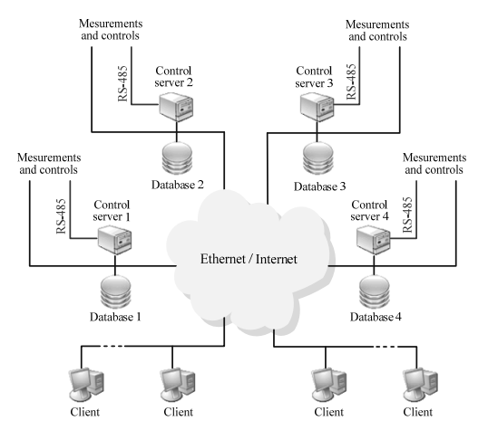
Communication in the system is carried out by Ethernet but some of devices are communicating with the control servers via RS-485 interface witch MODBUS protocol. Control servers provide information about the realized compensation process to clients’ applications. The client application has the ability to monitor the status of a part of the grid managed by each server and has got access to each database.
Events technology of Firebird database
Information about system changes is transmitted by the events technology of Firebird database [23, 24]. Events are simple notification messages transmitted asynchronously from the database server to the clients’ applications, initialized by the server. They act in a different way comparing to the typical mechanism of request-reply SQL databases.
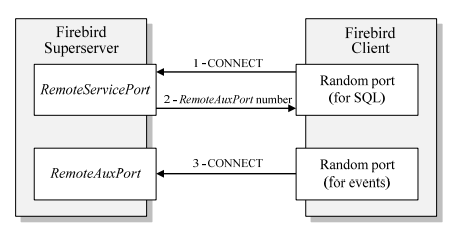
The mechanism of events uses an additional connection between the Firebird database server and a client’s application. After the client establishes a connection to a standard port to query SQL (RemoteServicePort), the server offers an additional communication channel by opening an additional port defined by the RemoteAuxPort configuration parameter and sends to the client information about this port number. The client’s application interested in receiving events may establish the additional connection to the offered RemoteAuxPort port. Diagram of client software and database server connecting process, with support for events technology, is shown in Figure 4 [25].
After establishing a connection with RemoteAuxPort the clients’ application declares that events are in the range of its interest by registering names of events in the Firebird database server.
After the event appears all clients’ applications that have registered this event will be informed of its occurrence. Clients receive information about the name of the event and the number of its appearance. Reaction of the client’s application to retrieve information about occurrence of such event depends on the programmer.
The event may be generated by the server for various cases set by the database administrator. As example in the described implementation, events associated with the grid configuration changes are generated by data table trigger. Trigger forwards the name of the table to the stored procedure. Next, the stored procedure calls POST_EVENT procedure with the received parameter. In this example, structure of a table containing information about the grid configuration and changes can be created by the command shown in Figure 5.
The INPUT field contains the number of the changed signal. The INPUTS_1 … INPUTS_N fields contain the binary values of all signals states.
In order to provide information about the table where change occurred it was created the stored procedure with one input parameter. The parameter content is passed by trigger which executed this procedure.


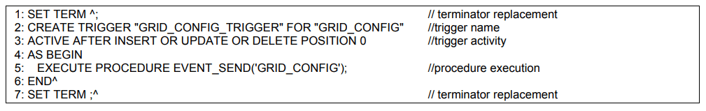


To automate the events transfer process triggers in the selected tables are created. For example, trigger for GRID_CONFIG table is created by the command shown in Figure 7. Thanks to use the Firebird database events technology, there is no need of periodical data refreshment to detect changes in the content stored in the database. Information is downloaded only in case of real change of the database content.
Detection of the regulation procedure parameters changes is realized in a similar way. Authorized user of client’s application can set: given value of the power factor, switching time limits of capacitors’ banks and filters of higher harmonics, values of currents and time intervals to determine stops of hoisting machines, etc.
Monitoring of the system
Information from control servers and databases of the reactive power compensation system allowed to design clients’ software for monitoring the compensation processes and for the electrical grid state visualization.
Communication is established by direct TCP/IP connections to each control server, combined with connection to each Firebird database with events receiving possibility.
The software is intended for use in PCs with Windows operating system and can run in desktop mode or in the touch panel mode, e.g. embedded in the control cabinet.
Clients’ applications provide access to actual and historical information related to the power grid state and to each compensator used in the reactive power compensation system. Examples of the information available in clients’ software in the touch panel mode are shown in Figure 9.

Results of operation
Figure 10 shows the active and reactive power measured waveforms of thyristor’s hoisting machine during the operation cycle.
It can be observed sudden changes of active power of few MW and reactive power of several MVAr. The highest consumption of reactive power occurs when thyristors are working with angle around 90o, so when the hoisting engine is starting. Such reactive power changes are not possible to compensate by capacitors’ banks. Switching of capacitors’ banks is limited by need of their discharging before next switching on. However it is possible to compensate such a reactive power changes by follow-up compensation using controlled synchronous machines.
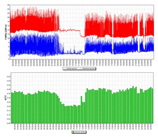
Figure 11 shows the selected measured waveforms in one of the power supply transformers of the part of the grid presented in Figure 3 and corresponding averaged 15- minute tgφ measurements with the automatic reactive power compensation system implemented in the mining plant. As controlled sources of reactive power were used capacitors’ banks and synchronous motor drives of the mine main ventilation system fans. Harmonics’ filters of working hoisting machines have been switched on permanently. The required value of tgφ factor was 0.2 and acceptable values should stay in the range of 0.0-0.4.
Selected waveforms include the periods of operation and stoppage of hoisting machines. In the present case effectiveness of compensation for load variations shown in Figure 11 depends on the regulation range of adjustable follow-up reactive power synchronous machines. These are underloaded high power synchronous motors driving the mine underground ventilation fans. These synchronous motors are equipped with microprocessor controlled units for excitation supply.
Conclusions and future work
Many enterprises cover the additional costs of electrical energy caused by improper management of the reactive power in spite of sufficient quantity of compensators and possibilities of controlling them. Experience taken from many Polish plants shows that attempts of reactive power compensation realized by human operators are often insufficient to provide the desired power factor. These attempts don’t allow to take into account other optimization criteria.
The solution is the real-time follow-up automatic reactive power compensation system responsing to: active and reactive power load changes, switching in the plant power grid, compensators availability and control range changes. Practical experience shows that the presented reactive power compensation system allows to utilize full compensation abilities of installed devices. It makes possible to eliminate or substantially reduce the additional fees for exceeding reactive power out of allowable range. Presented, developed by the author, multi-servers automatic reactive power compensation system has been implemented by JJA Progress company in the large mining plant in Poland.
Actually some elements of the system, due to its design, use a RS-485 communication standard. Planned modernization is based on use of hardware RS-485 to TCP/IP converters, allowing all devices to be accessed via Ethernet. Thanks to that each control server will get ability to communicate with each component of the system. This will increase the system reliability by replaceability of tasks performed by each server. Failed server will be automatically replaced with another.
Despite of developing new compensation equipment such as: static Var compensators (SVCs) with thyristor-switched capacitors (TSCs), thyristor-controlled reactors (TCRs), self-commutated pulse width modulation (PWM) converters capable properly control generation or absorption of the reactive power, the reactive power compensation in industrial power grids realized by capacitors’ banks, passive harmonics filters and underloaded synchronous machines is often acceptable for the users, both in technical and economic terms.
REFERENCES
[1] Dixon J., Moran L., Rodriguez J., Domke R.: Reactive Power Compensation Technologies: State-of-Art Review, Proc. of the IEEE. Vol.93. No.12, 2005, pp.2144-2164
[2] Igbinovia F. O., Fandi G., Švec J., Müller Z., Tlusty J.: Comparative review of reactive power compensation technologies, 16th International Scientific Conference on Electric Power Engineering (EPE) 2015, Kouty nad Desnou, 2015, pp.2-7
[3] Fryze S.: Active, reactive and apparent powers in nonsinusoidal systems (in Polish), Przegląd Elektrotechniczny, no. 7/1931, pp.193-203
[4] Ortega J. M. M., Payan M. B., Mitchell C. I.: Power factor correction and harmonic mitigation in industry, Industry Applications Conference, 2000. Conference Record of the 2000 IEEE, Rome, 2000, vol.5, pp.3127-3134
[5] Balci M. E., Hocaoglu M. H.: Comparison of power definitions for reactive power compensation in nonsinusoidal conditions, 11th International Conference on Harmonics and Quality of Power, 2004, pp.519-524
[6] Angelo B.: Handbook of Power Quality. John Wiley & Sons, 2008
[7] Fehr R.: Power Factor Correction. In Industrial Power Distribution , Wiley-IEEE Press, 2016, pp.319-330
[8] Heger C. A., Sen P. K., Morroni A.: Power factor correction — A fresh look into today’s electrical systems. 2012 IEEEIAS/PCA 54th Cement Industry Technical Conference, San Antonio, TX, 2012, pp.1-13
[9] Xu H., Wang C.: Power Factor Improvement in Industrial Facilities Using Fuzzy Logic Excitation Control of Synchronous Motor, International Conference on Computational Intelligence and Software Engineering, CiSE 2009, Wuhan, 2009, pp.1-4
[10] Al-Hamrani M. M., Von Jouanne A., Wallace A.; Power factor correction in industrial facilities using adaptive excitation control of synchronous machines, Conference Record of the 2002 Annual Pulp and Paper Industry Technical Conference, Toronto, Ontario, Canada, 2002, pp.148-154
[11] Yehia M., Ramadan R., El-Tawil Z., Tarhini K.: An Integrated Technico-Economical Methodology for Solving Reactive Power Compenation Problem, IEEE Transactions on Power Systems, Vol. 13, No. 1, 1998, pp.54-59
[12] Ekel P., Ansuj S., Schinzinger R., Prakhovnik A., Razumovsky O.: Automation of reactive power compensation in industrial power systems, Proc. of the Third IEEE Conference on Control Applications, Glasgow, 1994, vol.1, pp.479-484
[13] Herman L., Papic I.: Optimal control of reactive power compensators in industrial networks, Proc. of 14th International Conference on Harmonics and Quality of Power – ICHQP 2010, Bergamo, 2010,pp.1-6
[14] Das J. C.: Reactive power flow control and compensation in the industrial distribution systems, Industrial and Commercial Power Systems Technical Conference, Conference Record, Papers Presented at the 1993 Annual Meeting, St. Petersburg, FL, USA, 1993, pp.128-136.
[15] Helmi B. A., D’Souza M., Bolz B. A.: The application of power factor correction capacitors to reserve spare capacity of existing main transformers, Industry Applications Society 60th Annual Petroleum and Chemical Industry Conference, Chicago, IL, 2013, pp.1-6
[16] Li F., Zhang W., Tolbert L. M., Kueck J. D., Rizy D. T.: Assessment of the Economic Benefits from Reactive Power Compensation, 2006 IEEE PES Power Systems Conference and Exposition, Atlanta, GA, 2006, pp.1767-1773
[17] Schaefer R. C.: Excitation control of the synchronous motor, IEEE Tran. Ind. Appl. 1999, 35(3), pp.694–702
[18] Hyla M.: Power supply unit for the excitation of a synchronous motor with a reactive power regulator, Mining – Informatics, Automation and Electrical Engineering, 1(521), 2015, pp.17-21
[19] Sagiroglu S., Colak I., Bayindir R,: Power factor correction technique based on artificial neural networks, Energy Conversion and Management, vol .47, no. 18-19, November 2006, pp.3204-3215
[20] Colak I., Bayindir R., Bay O.F.: Reactive power compensation using a fuzzy logic controlled synchronous motor, Energy Conversion and Management, vol. 44, no. 13, August 2003, pp.2189-2204
[21] Wysocki W., Szlosek M.: Compensation of reactive power as a method for reducing energy losses: On the example of calculations and measurements of load flow through the distribution transformer in one of the polish distribution network, 2011 11th International Conference on Electrical Power Quality and Utilisation (EPQU), Lisbon, 2011, pp.1-5
[22] Hyla M., Gierlotka.K.: The optimization on the control of reactive power compensators in industry power grid, International Conference on Electrical Drives and Power Electronics. EDPE 2003, The High Tatras, Slovak Republik, 24-26 September 2003, pp.422-427
[23] Borrie H.: The Firebird Book. A Reference for Database Developers, Apress, 2004
[24] Babuskov M.: The Power of Firebird Events, Firebird Conference, 13-15.12.2005, Prague 2005
Autor: dr inż. Marian Hyla, Silesian University of Technology, Faculty of Electrical Engineering, Department of Power Electronics, Electrical Drives and Robotics, ul. B. Krzywoustego 2, 44-100 Gliwice, Poland E-mail: marian.hyla@polsl.pl
Source & Publisher Item Identifier: PRZEGLĄD ELEKTROTECHNICZNY, ISSN 0033-2097, R. 94 NR 8/2018. doi:10.15199/48.2018.08.27
