Published by Mohammed A. IBRAHIM1, Bashar M. SALIH2, Mahmoud N. Abd3,
Power Technical Engineering Department, Northern Technical University (1,2)
Ninavah Electricity Distribution, Directorate General Directorate of North Distribution Electricity, Ministry of Electricity, Iraq (3)
ORCID. 1. /0000-0003-3182-2771, 2. 0000-0002-2437-0765, 3. https://orcid.org/0000-0002-8018-0093
Abstract. The main objective of this research work is to build a simulation model of a power system based on MATLAB to detect the faults (symmetric and asymmetric). We also know that the electric power system is made up of important and costly components, so these parts must be protected. The major purpose of this article is to studies and analysis the different faults and declares the impact on power system. Two types of protection are used, differential protection and overcurrent protection. This work is approach to MATLAB/SIMULINK package. In this work, a laboratory board was designed to represent an electrical power system consist of three stages: generation units, transmission lines and distribution systems.
Streszczenie. Głównym celem niniejszej pracy badawczej jest zbudowanie modelu symulacyjnego systemu elektroenergetycznego w oparciu o MATLAB do wykrywania zwarć (symetrycznych i asymetrycznych). Wiemy, że system zasilania elektrycznego składa się z ważnych i kosztownych komponentów, dlatego te części muszą być chronione. Głównym celem tego artykułu jest badanie i analiza różnych usterek oraz deklaracja wpływu na system elektroenergetyczny. Stosowane są dwa rodzaje ochrony: zabezpieczenie różnicowe i zabezpieczenie nadprądowe. Praca ta jest podejściem do pakietu MATLAB/SIMULINK. W pracy zaprojektowano tablicę laboratoryjną do reprezentowania systemu elektroenergetycznego składającego się z trzech etapów: jednostek wytwórczych, linii przesyłowych i systemów dystrybucyjnych (Zabezpieczenie transformatora i linii przesyłowej w systemie elektroenergetycznym w oparciu o MATLAB Simulink)
Keywords: Differential relay, Overcurrent relay, Power system, Power transformer, MATLAB Simulink. Słowa kluczowe: przekaźnik różnicowy, przeciążenie prądowe, transformator, zabezpieczenie
Introduction
Right now, in power system network, fault is a major problem. With an increasing demand for electricity, the distribution system of electricity is growing year on year and for that reason, the protection of power system equipment and maintenance is very important in order to reduce costs and increase the life of the reliable and uninterrupted power system equipment [1]. The power system must be operating in a secure method at all times. Faults will result in a total blackout or a partial system. In order to protect the power system from the disturbances that have happened, a protection system is essential. There are many types of protective relays obtainable to solve this problem [2]. The benefit of protection relay is to reduce a dangerous damage in the electrical equipment at fault occurs, it is designed according to the basis of reliability, selectivity and fast response [3]. In order to protect this equipment from such problems, we need some protective measures. These shall consist of protective relays and circuit breakers. If there is a fault in the system, an automatic protection device is required to insulate the faulty section and maintain a healthy section in operation [4]. Power transformer is the bulk essential applications used in substations and main station. Power transformer is very important toward the effective functioning in the power system. Differential operation is the most popular method of operation of the various power transformer operations [5].
The overcurrent protection plays an essential role in protecting the power system due to unexpected increase in the current that damages the components of the system [6]. As we know, for (T.L) protection the circuit breaker is mounted and it relies on ternary line fault because this type of fault is hyper high compared to the other types of faults. There are two faults on the 3-phase balanced fault power system and the unbalanced faults in the power system are phase to ground, phase-to-phase, phase to phase to ground [7]. This project study the rumor fault types, which classified as symmetrical and unsymmetrical fault. MATLAB environment is used in order to analysis this circuit and obtain on the different simulation parameters of fault types.
Literature review
E. Ali, A. Helal, H. Desouki, K. Shebl, S. Abdelkader, O.P. Malikc, 2018 [8]. These authors work on three-phase power transformer has parameters (25 MVA, 138/13.8 KV, 60 Hz star–star connection. 5 Km (T.L) connected to a 13.8 kV equivalent source). Studied the protection of power transformer based differential relay; also, taking the internal and external fault, the system is simulated based on MATLAB/Simulink software. Satish Karekar, Tripti Barik, 2016 [9]. These authors work on the (T.L) has parameter (440 KV, 300 km length). Studies faults locations on EHV (T.L) parameter are convenient by using MATLAB software, and detection and analysis of faults (symmetrical and unsymmetrical) on long (T.L). The purpose of this paper is to modulate, and simulate the power system based on MATLAB/Simulink. Depending on the results that obtained by modulating and simulating the differential and overcurrent relay, this model will be expand in the future.
The proposed method The aim of this research is to design and implement a laboratory board for an electrical power system, since this design was one of the graduation projects for students of preliminary studies at the College of Engineering, compared with the results of MATLAB Simulink. The main purposes of this project are as follows:
• To study the existing fault classification and to detect faults for the power transformer and (T.L) in the power system.
• Appropriate design of a power system model with specification power system components.
• Power transformer and (T.L) specifications used by Terco Corporation.
• Design MATLAB Simulink model for the suggested methodology using MATLAB 2015a software environment.
Faults and Classifications
When the operation of power system under balanced circumstances, all components are carried. A fault in the circuit can obtained due to the failure that intervenes with the ordinary current flow. When the system insulation fails due to low impedance a path either between phases to ground or phases a short [1]. Circuit fault will occur; can classified this short circuit faults as:
Symmetrical Faults
In this fault’s kinds, the three phases are short circuit to earth or to each other. These faults are considered as a balance case and giving a sense that the system remain symmetrical. The most severe kind of fault is that included large current, for this reason, calculations of the balanced short-circuit case shall be made to determine these large currents.
Asymmetrical Faults
Asymmetrical fault included one phase or two and three phases line fault becomes unbalanced, these kinds of faults happen between lines or line to ground. Faults occur between phases and phase to ground are called asymmetrical fault. While asymmetrical shunt fault considered as an unbalanced in the line impedances. The shunt fault can classified as:
• One phase to ground fault (L-G).
• Two phases fault (L-L).
• Two phases to ground fault (L-L-G).
• Three phases fault (L-L-L).
• Three phases to ground fault (L-L-L-G).
Differential Protection
When the discrepancy between the primary and secondary current equal to zero, this mean that the system is healthy. In the strict transformer, there is no loss of power in the transformer, and eddy current and core losses appeared practically in the transformer in spite of no operation current. Mismatch of the phase shift, (CTs) ratio, ratio of the transformer and tap-changer. Because of this current, it will not be zero. Because of this relay, the sensitivity and the trip signal of the differential relay may decrease due to an increase in uncalled tripping. We use a bias differential relay to avoid this [10].
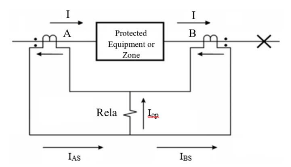
Figure (1) illustrates single phase of a three-phase differential protection (DP). Figure (1) shows that both of (CTs) enclose the protection zone. Due to its normal tendency, (DP) does not offer backup protection to the rest of the protective devices, for that cause; this form of protection scheme is commonly recognized as a protection scheme of unit. (CTs) current that passes through the conductors, these conductors are name as trial wires. In no condition of fault, the input current of the IP protection unit is same as to the output current of the protection zone at all instants. When considering the (CTs) A. The current that is carrying by a trial wire of (CTs) A and (CTs) are equal to:
(1) IAS = αA IP – IAe
(2) IBS = αB IP – IBe
Where: αA: Ratio of (CT) A; αB: Ratio of (CT) B; IAe, IBe: (CT) A and (CT) B Secondary excitation current.
By considering that the transformation ratios are equally, αA= αB =α, the relay operation current Iop is equal to:
(3) Iop = IAe – IBe
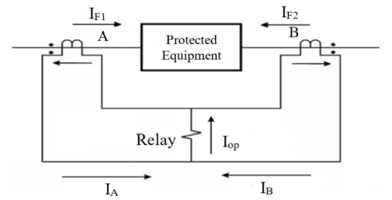
At the time of out-of-zone system faults, the Iop of relay operating current is quite small, but doesn’t to be zero. But when an inside zone fault occurs (internal fault), the input current is no secular worth to the output. Figure (2) represents the differential relay within internal zone [11, 12 and 13].
(4) Iop = α(IF1 + IF2) – IAe – IBe
In terms of the operational characteristics of the electromechanical relay effect, the inclination of the characteristics increases. The bias differential relay (DR) is used for the (DR) of the high-power transformer. Figure (3) illustrates the operational characteristics of the (DR).
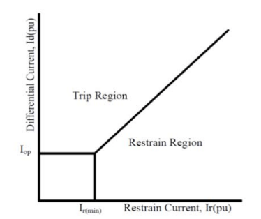
When the pick-up ratio is set to a higher bias, the pickup ratio is set to a positive (tripping) area, when the pick-up ratio is set to a smaller bias; the pick-up ratio is set to a negative (blocking) area. In this kind of relay, operating coil is putting in parallel with the restraining coils. Conflicting torque is created by restraining coils to the operating torque. When the faults occur out of zone, the restraining torque is bigger than operating torque. Therefore, the relay is no operating. When the fault occurs internal, the relay is operating when the operating torque is greater than the bias torque. The changing in the turn’s number of the restraining coil will effect on the bias torque [10].
Over Current Relay (OCRs)
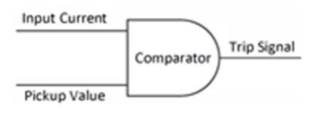
The function of the OCR is to compare the actual measured value with the preset value. The logical representation of this OCR as shown in Figure (1). As the value of the input current overcome the smallness value, the relay sense this putting-up and send a trip signal to the circuit breaker to disconnect the protected device, and open its contact to disjunction the protected device. Once the relay locates a fault, it is called fault pickup in this case. After the fault has been picked up, the relay can transmit the trip signal instantaneously. (Instantly over current relay) or may be requested for a certain period of time before a trip signal is released (time over current case) [15, 16, 17, 18 and 19].
OCRs can be classified according to their operation in to three categories:
• Instantaneous OCRs
• Definite Time OCRs
Inverse Definite Minimum Time (IDMT) OCRs
Protection Part Algorithm
Figure (5) represents the algorithm of case study with two protection types.

Molding and Simulation
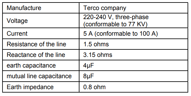
Data for this research were taken from the TERCO Company of Sweden. A model is designed for a laboratory electrical power system, where the system consists of three stages the generation system, (T.L) system and distribution system. Two types of protection are used, first one (DR) to protect the power transformer and the second one (OC) protect the (T.L). Table (1) represents the parameter of the power transformer.
Table (2) represents the parameter of the (T.L), the description MV1420 Line Model corresponds to a (T.L) of a length 136 km, 77 KV, 100 A and 13 MW.
Table 1. Terco power transformer (MV1915) specifications
Table 2. Parameter of the (T.L)
Experimental and Simulation Results
Figure (6) illustrate the diagram of the power system module based on MATLAB/Simulink.

Figure (7) illustrate the contents of differential relay subsystem block.
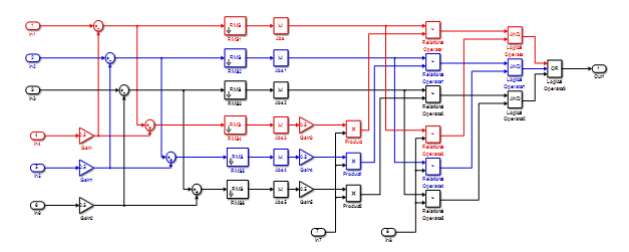
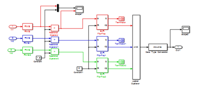
Figure (8) illustrate the contents of overcurrent relay subsystem block. Figure (9) illustrate the design of the laboratory board for the electrical power system.

Results and discussion
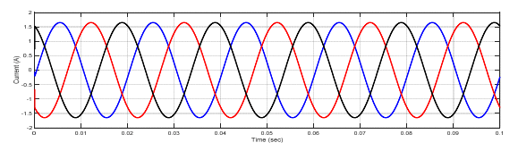
Case No.1: At no fault (normal operation):
The simulation results of voltages and currents for power system at sending end, receiving end and also T.L are shown in figures (10 – 15).

Case No.2: Fault at sending side of the transformer
The output signal of the differential relay when fault occurred at time 0.1 (sec) is given in figure (16).
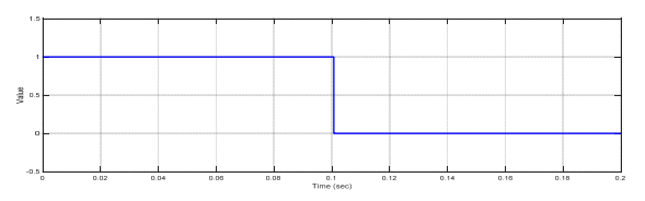
Figure (17) illustrate the current signal when the type fault is three phases to ground.
Figure (18) illustrate the voltage signal when the type fault is three phases to ground.
Case No.3: Fault at (T.L).
Figure (19) illustrate the current signal when the type fault is three phases to ground.
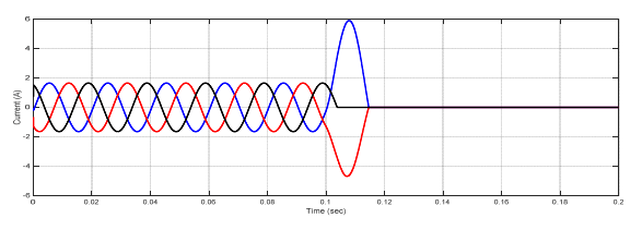
Figure (20) illustrate the voltage signal when the type fault is three phases to ground

Case No.4: Fault at receiving transformer
Figure (21) illustrate the current signal when the type fault is three phases to ground.
Figure (22) illustrate the voltage signal when the type fault is three phases to ground.
Conclusions
In this paper, the differential relay and overcurrent relay characteristics are advanced using MATLAB/Simulink. The performance characteristics of differential and overcurrent relay were evaluated at a location with three phase faults, and also study the various faults that occur in power system. (MV1915) power transformer and (MV1420) (T.L) Sweden Company (Terco-company). As shown from figure (10-15), when no faults occurred, the current and voltage normal case. As shown from figure (16-18) when internal fault occurred in sending side of the transformer, the differential relay will send signal to the circuit breaker at time (0.1 sec), this signal will be circuit breaker open, because the currents signal of secondary (C.Ts)A are don’t similar to that obtained from secondary (CTs)B, that due to operation of relay. As shown from figure (19-20) the fault occurred in (T.L), the type of fault three phase to ground, when the current increase up to set value the over current relay will be send signal to the circuit breaker, due to operation of the circuit breaker. As shown from figure (21- 22) the fault occurred in internal of receiving transformer.
Acknowledgment: The authors would like to thank Northern Technical University -Technical College of Engineering / Mosul, to provide a simulation package for us to finish our work.
REFERENCES
[1] P. Maji and G. Ghosh, “Designing Over-Current Relay Logic in MATLAB,” vol. 8, no. 3, pp. 40–43, 2017.
[2] H. Eteruddin et al., “Line Differential Protection Modeling with Composite Current and Voltage Line Differential Protection Modeling with Composite Current and Voltage Signal Comparison Method,” no. July, 2014, doi: 10.12928/TELKOMNIKA.v12i1.1966.
[3] N. H. Hussin et al., “Modeling and simulation of inverse time overcurrent relay using MATLAB/Simulink,” Proc. – 2016 IEEE Int. Conf. Autom. Control Intell. Syst. I2CACIS 2016, no. October, pp. 40–44, 2017, doi: 10.1109/I2CACIS.2016.7885286.
[4] M. P. Thakre and V. S. Kale, “D Istance P Rotection for L Ong T Ransmission L Ine Using Pscad,” 2018 Int. Conf. Adv. Electr. Electron. Eng., vol. 6, no. 6, pp. 2579–2586, 2014.
[5] P. P. Aye, W. K. Myint, and W. T. Zar, “Modelling and Simulation of Protection for Power Transformer at Primary Substation by Using Differential Protection,” Int. J. Sci. Eng. Appl., vol. 7, no. 11, pp. 474–478, 2018, doi: 10.7753/ijsea0711.1014.
[6] P. Mehta and V. Makwana, “Modelling of overcurrent relay with inverse characteristics for radial feeder protection using graphical user interface,” 2017 Int. Conf. Intell. Comput. Instrum. Control Technol. ICICICT 2017, vol. 2018-Janua, pp. 74–79, 2018, doi: 10.1109/ICICICT1.2017.8342537.
[7] S. Maharana and C. Sharma, “Fault Analysis of Transmission Line,” vol. 1, no. 4, pp. 4–7, 2014.
[8] E. Ali, A. Helal, H. Desouki, K. Shebl, S. Abdelkader, and O. P. Malik, “Power transformer differential protection using current and voltage ratios,” Electr. Power Syst. Res., vol. 154, pp. 140– 150, 2018, doi: 10.1016/j.epsr.2017.08.026.
[9] S. Karekar and T. Barik, “A Modelling of 440 KV EHV Transmission Line Faults identified and Analysis by Using MATLAB Simulation,” Int. J. Adv. Res. Electr. Electron. Instrum.Eng., vol. 5, no. 3, pp. 1242–1249, 2016, doi: 10.15662/IJAREEIE.2016.0503007.
[10] N. S. Jadhav and A. R. Thorat, “Design of a differential relay for 1000-kV Transmission Line using MATLAB,” 2013 Int. Conf. Energy Effic. Technol. Sustain. ICEETS 2013, pp. 1164–1168, 2013, doi: 10.1109/ICEETS.2013.6533551.
[11] P. N. Upadhayaya and V. H. Makwana, “Modelling & simulation of transformer biased differential protection scheme in laboratory environment,” 2017 Int. Conf. Intell. Comput. Instrum. Control Technol. ICICICT 2017, vol. 2018-Janua, pp. 68–73, 2018, doi: 10.1109/ICICICT1.2017.8342536.
[12] Nassim A. Iqteit1, Khalid Yahya2, “Simulink model of transformer differential protection using phase angle difference based algorithm” International Journal of Power Electronics and Drive System (IJPEDS), Vol. 11, No. 2, pp. 1088~1098, June 2020.
[13] Kaur, A., Brar, Y., & G., L. “Fault detection in power transformers using random neural networks”. International Journal Of Electrical And Computer Engineering (IJECE), 9(1), 78. doi: 10.11591/ijece.v9i1. pp. 78-84, 2019.
[14] Outzguinrimt, H., Chraygane, M., Lahame, M., Oumghar, R., Batit, R., & Ferfra, M. “Modeling of three-limb three-phase transformer relates to shunt core using in industrial microwave generators with n=2 magnetron per phase”. International Journal of Electrical and Computer Engineering (IJECE), 9(6), 4566. doi: 10.11591/ijece.v9i6. pp4556-4565, 2019.
[15] M. S. Almas, R. Leelaruji, and L. Vanfretti, “Over-current relay model implementation for real time simulation & Hardware-inthe-Loop (HIL) validation,” IECON Proc. (Industrial Electron.Conf., pp. 4789–4796, 2012, doi: 10.1109/IECON.2012.6389585.
[16] A. Akhikpemelo, M. J. E. Evbogbai, and M. S. Okundamiya, “Overcurrent relays coordination using MATLAB model,” J. Eng. Manuf. Technol., vol. 6, no. March, pp. 8–15, 2018.
[17] Mohammed A. Ibrahim, Waseem Kh. Ibrahim, Ali N. Hamoodi, “Design and Implementation of Overcurrent Relay to Protect the Transmission Line” International Journal of Engineering Research and Technology, Vol. 13, No. 11 (2020), pp. 3783-3789.
[18] Ahmed M. T. Ibraheem, Mohammed A. Ibrahim and Abdullah K. Shanshal, “PLC Based Overcurrent Protection of Threephase Transmission Line”, 1st International Multi Disciplinary Conference Theme: Sustainable Development and Smart Planning, IMDC-SDSP 2020, Cyperspace, 28-30 June 2020.
[19] Bashar M. SALIH, Mohammed A. IBRAHIM, Ali N. HAMOODI, “Differential Relay Protection for Prototype Transformer”, PRZEGLĄD ELEKTROTECHNICZNY, ISSN 0033-2097, R. 97 NR 6/2021.
Source & Publisher Item Identifier: PRZEGLĄD ELEKTROTECHNICZNY, ISSN 0033-2097, R. 97 NR 10/2021. doi:10.15199/48.2021.10.04
