Published by Payal jangilwar1, Prof. Balram Yadav2, 1M-tech scholar, Department of Electrical and Electronics Engineering, Scope College of Engineering, Bhopal, 2HOD, Department of Electrical and Electronics Engineering, Scope College of Engineering, Bhopal.
Abstract – Electric Vehicles plays an important role in energy storage management in microgrid. This mechanism is managed by grid to vehicle technology in storing energy and vehicle to grid technology in supplying the energy back to grid. We need a proper architecture to make this concept reality. This paper represents a architecture to establish a V2G and G2V concept employing Dc fast charging which is also called as level 3 charging. The model is prepared with microgrid test system with DC fast charging architecture. The simulation results shows that electric vehicle batteries give proper regulation of power in microgrid by using V2G and G2V concept.
Keywords: Vehicle to grid, grid tie inverters, automotive and power generation units, battery, electric vehicle.
1. INTRODUCTION
Electric Vehicles are increasing their demand nowadays. It can draw power from on-board source of electricity. Electric vehicles are better in working than gasoline-powered vehicles as they reduces pollution to much extent, also electric vehicles are mechanically simpler than gasoline-powered vehicles. Batteries of electric vehicles can used as a potential energy storage devices in microgrid. It is proven that electric vehicles are feasible solution for energy management system of microgrid. It employs V2G and G2V technology using level 3 charging architecture, for charging electric vehicles. Previously level 1 and level 2 AC charging scheme was used to charge electric vehicles. These scheme leads to distribution losses such as voltage fluctuations, power losses and transformer overloads this can harms the distribution system. Therefore to reduce these losses DC fast charging scheme(level 3) is employed and to allow bi-directional energy flow V2G and G2V technology is used. This paper presents a dc quick charging station with V2G technology.
Simulation result shows that energy storage management of microgrid effectively working with this technology. This paper describes DC fast charging configuration, microgrid test system and control system.
2. DC CHARGING SYSTEM DC
fast charging scheme is more better than level 1 and level 2 AC charging system. It reduces charging time to 20-30 minutes about 80% charging has to be done within this time. It uses 200-600V input voltage and about 30 amps input current to charge electric vehicles. DC fast charger bypasses the onboard charging device by supplying power directly to battery of electric vehicles.
2.1 CALCULATION OF PARAMETERS OF DC FAST CHARGING UNIT
DC charging unit needed DC connection band its control is also necessary. To reduce the fluctuations of DC bars due to large no if electric vehicles connected to it, the value of capacitor should be high. The maximum values of current and voltage are the reference values because electric vehicle cannot exceed maximum power value. Maximum value of power can be given by
PEA =Imax* Vmax
It is important to make visible power calculations, to deal with the fact that load coefficient is to be formed in power system, the power to be taken from the no of slots to which the EV to be charged and connected. The main function of capacitor is to maintain the fluctuations under certain level. “ when switching status is low, switching block at the bottom output terminal that the DC connection is shorted at the negative and when switching status is high switching block works effectively and DC connection is shorted to positive end”.
2.2 DC FAST CHARGING STATION CONFIGURATION
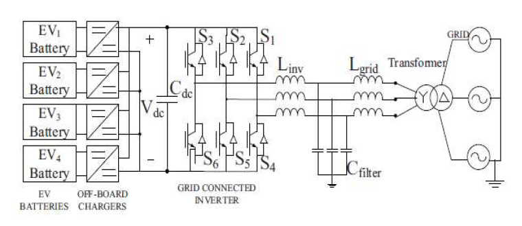
DC fast charging station configuration includes EV batteries, on-board charger, grid-connected inverter, dc bus, LCL filter and step up transformer. It implements V2G-G2V framework in microgrid. There are two important components of this charging station are
a) Battery charger
b) Grid-connected inverter and LCL filter

a) Battery charger configuration
DC chargers for Dc fast charging system are situated off-board nd embedded in a EVSE. The important component of an off-board charger employing V2G functionality is bidirectional dc-dc converter. Bidirectional DC-DC converter are judged by current and voltage supply from one side. “The current in double sided transducers must be travelled in both sides. As we know there is a no power key this way, the one-way key MOSFET or IGBT are placed parallel in battery charger circuit. Battery chargers are acts as power converters. These charges can be used in three different ways buck, boost and buck-boost converters. Two IGBT switch used for two different values
1) Buck mode operation: It is a charging mode, where power flows from grid to vehicle. In this mode when upper switch is operating ; Ie having low value converter act as a buck converter and syeps down the ‘input voltage(Vdc) to battery charging voltage( V). When switch is off, through inductor and diode of lower switch current completes its return path.
Vbatt = Vdc * D
D is the duty ratio of upper switch
2) Boost mode operation: the converter is act as boost converter when lower switch is cooperating. It steps up the battery voltage (Vbatt) to DC bus voltage (Vdc). When the switch is in on state through an inductor, current continues to flow and completes its path through anti parallel diode of upper switch and the capacitor. It is a discharge mode. In this case power flows from vehicle to grid. Output voltage in boost mode is given by
Vdc = Vbatt/ 1-D’
Where D’ is duty ratio of lower switch.
b) Grid connected inverter and LCL filter
The three phase grid connected inverter is used to convert AC power into DC power and also permits the reverse flow of current through anti parallel diodes of the switches. Double-sided power flow has to be flow using six-pulse inverter. More the number of pulses, less the current fluctuations. There are two types of filter active filter and passive filter. In this system we are using passive filter as they interface with system and reduce harmonics. Inductor filters are first order filter and required large of inductor to reduce harmonics but this leads to voltage drop. LC filter is second order filter. By using this filter inrush current and output capacitor problems arrives. Therefore LCL filter is used in this system which reduces harmonics and obtained pure sinusoidal voltage and current. The main advantage of using this filter it has two inductor therefore system remains in steady state.
3.CONTROL SYSTEM
a) Off-board charger control
For charging/ discharging control of battery charger, current control strategy using PI controllers is used. Reference battery current get compared with zero, to determine polarity of current wave. This is to be done to decide whether it is charging mode or discharging mode. When any one mode is get selected then reference current is compared with measurement current to find error. This error is passed through PI controller, this generates pulse for Sbuck/ Sboost, It is noted that “ Sbuck will turned off in charging mode and Sboost will turned off in discharging mode”.
b) Inverter control
In synchronism with reference frame a cascade control is provided for inverter controller. Controller structure is made up of two outer voltage control loop and two inner current control loops. D-axis outer loop has control over dc bus voltage and inner loop has control on active AC current. Also, q-axis outer loop controls AC voltage and q-axis inner loop regulates reactive current.
4. MICROGRID TEST SYSTEM CONFIGURATION
In this test system A 100KW wind turbine and 50 KW solar PV array act as generation sources. EV battery storage system included 4EV batteries which are connected to 1.5 KV dc bus of charging station. A boost converter has maximum power point tracking controller, to this boost converter a solar PV is connected. Distribution feeder of 25KV and equivalent transmission system are included in utility grid. At common coupling point(PCC) a wind turbine is connected to microgrid, this turbine is driven by doubly-fed induction generator. Function of transformer connected is to step up the voltages and connect the respective ac systems to utility grid.
5. SIMULATION RESULTS
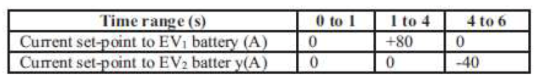
The designing and modulation of DC fast charging system for electric vehicle in microgrid is successfully and the results shows that it works precisely. Wind turbine is work preferably at rated speed giving maximum power up to 100KW. Solar photovoltaic system is checked under standard conditions it can provides maximum output power of 50KW. To work at unity power factor, the 480V AC bus is connected to 150KW resistance load. According to reference of CGI reactive current is set to zero. It is proven that “ the initial state of charge of electric vehicle is set to 50% and once the steady conditions are obtained V2G and G2V power transfer is carried out using batteries of EV1 and EV2”. Table 1 shows current set points for battery charging circuits of EV1 and EV2. Fig 3 and 4 shows battery parameters when EV! Is operating in V2G and EV2 is operating in G2V modes.
Table 1. Current Set-points to EV Batteries
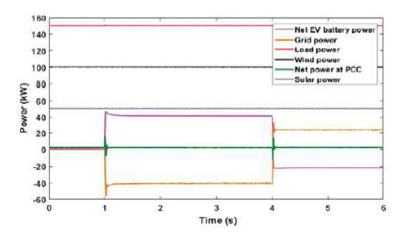
Active power profile of various components in the system is shown in fig 5. The power from grid changes to adapt power transfer by electric vehicles. “ the negative polarity of grid from 1s to 4 shows power transferred from vehicle to grid”. The change in polarity at 4s shows power is transferred by grid to charge the vehicle. This shows the V2G-G2V operation. Net power PCC is zero, this shows that power is balanced in the system.
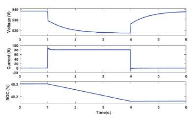
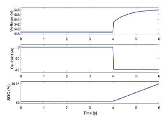
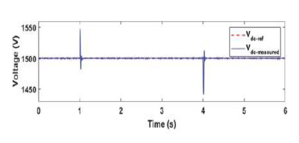
Fig 6. shows the regulation of Dc bus voltage by outer voltage control loop of inverter at 1500V. Reference current tracking by inner control loop is shown in fig 7.
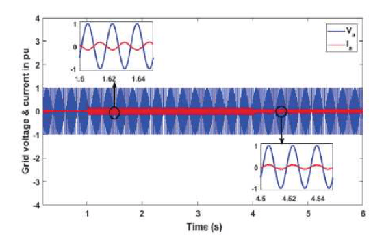
The harmonic distortion analysis is completed on grid injected current and the result is shown in fig 9. As said in IEEE std 1547 “ harmonic current distortion on power systems 69KV and below are limited to 5% THD. The THD of grid injected current is obtained as 2.31% and carried out by LCL filter”.

6. CONCLUSION
Architecture of Dc fast charging in microgrid is presented in this paper. DC system with off-board chargers and inverter is designed to connect the EVs to microgrid. Control system is designed to allow bidirectional energy flow. Simulation results shows the smoot power flow between EVs ad microgrid. In this work active power regulation in microgrid has been considered and V2G system can be used for reactive power control & frequency regulation.
REFERENCES
[1] C. Shumei, L. Xiaofei, T. Dewen, Z. Qianfan, and S. Liwei, “The construction and simulation of V2G system in micro-grid,” in Proceedings of the International Conference on Electrical Machines and Systems, ICEMS 2011, 2011, pp. 1–4.
[2] S. Han, S. Han, and K. Sezaki, “Development of an optimal vehicle-togrid aggregator for frequency regulation,” IEEE Trans. Smart Grid, vol. 1, no. 1, pp. 65–72, 2010.
[3] M. C. Kisacikoglu, M. Kesler, and L. M. Tolbert, “Single-phase on-board bidirectional PEV charger for V2G reactive power operation,” IEEE Trans. Smart Grid, vol. 6, no. 2, pp. 767–775, 2015.
[4] A. Arancibia and K. Strunz, “Modeling of an electric vehicle charging station for fast DC charging,” in Proceedings of the IEEE International Electric Vehicle Conference (IEVC), 2012, pp. 1–6.
[5] K. M. Tan, V. K. Ramachandaramurthy, and J. Y. Yong, “Bidirectional battery charger for electric vehicle,” in 2014 IEEE Innovative Smart Grid Technologies – Asia, ISGT ASIA 2014, 2014, pp. 406–411
[6] joao c. Ferreira, Vitor monteriro, joao l. Alfonso, Alberto silva, “ smart electric Vehicle Design” conference paper IEEE, June 2011, 758-763, Germany.
[7] Aykut Fatih GUVEN, Salih Burak AKBASAK, “DC fast charging station modeling and control of elecrtric vehicles”, Karadeniz Fen Bilimleri Dergisi the black sea journal of science, Dec 2021, 680-704, Yalova, Turkey.
[8] clement-NYns K haesen E. and Driesen J,” the impact of charging plug-in-hybrid electric vehicleso a residential distribution grid”, tans power system 25(1), 2010, 371-388.
[9] Seshasai bagdi, A. Apparao, Venkateshwara Rao K.M., “ Vehicle to grid technology employing Dc fast charging configuration in microgrid using Fuzzy controllers”, JUNi khyat , volume 11 ,Jan 2021, 752-760 Srikakulam, Vizianagaram ,India.
[10] Femina Mohhamad Shaeel, OM P. Malik, “ Vehicle to grid technology in microgrid using Dc fast charging architecture” IEEE Canadian conference of electrical and computer engineering, 2019,1-4, Calgary, Canada.
Source & Publisher Item Identifier: International Research Journal of Engineering and Technology (IRJET) e-ISSN: 2395-0056 Volume: 09 Issue: 07 | July 2022 http://www.irjet.net p-ISSN: 2395-0072
