Published by Marian HYLA, Silesian University of Technology, Department of Power Electronics, Electrical Drives and Robotics. ORCID: 0000-0001-6466-7398
Abstract. The paper presents the problems of the influence of a high power thyristor hoisting machine on the mine’s power supply grid. The results of the real object measurements when the machine is powered from a 12-pulse rectifier with common, symmetrical firing angle control are presented. A comparative analyses were carried out in terms of reactive power and higher harmonics for symmetrical and asymmetric firing angle of thyristors based on simulation tests. The influence of the rectifier control method on the operating conditions of the automatic reactive power compensation system was indicated. Practical aspects, not included in the simulation model, have been emphasized.
Streszczenie. W artykule zaprezentowano zagadnienia wpływu tyrystorowej maszyny wyciągowej dużej mocy na sieć zasilającą kopalni. Przedstawiono wyniki pomiarów na obiekcie rzeczywistym przy zasilaniu maszyny z 12-pulsowego prostownika o sterowaniu symetrycznym wspólnym. Przeprowadzono analizę porównawczą pod kątem mocy biernej i wyższych harmonicznych dla symetrycznego oraz asymetrycznego kolejnościowego sterowania tyrystorów na podstawie badań symulacyjnych. Wskazano wpływ metody sterowania na warunki pracy systemu automatycznej kompensacji mocy biernej. Zwrócono uwagę na aspekty praktyczne, nie uwzględnione w zastosowanym modelu symulacyjnym. (Kompensacja mocy biernej w sieci 6 kV z 12-pulsową tyrystorową maszyną wyciągową)
Keywords: hoisting machine, thyristor rectifier, asymmetric control, reactive power compensation
Słowa kluczowe: maszyna wyciągowa, prostownik tyrystorowy, sterowanie asymetryczne, kompensacja mocy biern
Introduction
The purpose of reactive power compensation is to relieve the electric grid from the flow of reactive currents. This is achieved by eliminating the phase shift between the fundamental harmonics of the current and voltage and the elimination of higher harmonics of the load currents, regardless of the shape of the supply voltage [1, 2].
In practice, there are many definitions of reactive power [3-5]. In industrial power grids partial compensation is usually applied. It consists in the compensation of the fundamental current harmonic in order to keep the value of the power factor within acceptable limits, and thus – to limit active power losses and voltage drops in the supply lines. The higher harmonics content in the load current are limited by means of passive higher harmonic filters, which are also the source of the capacitive reactive power of the fundamental harmonic. With partial compensation as reactive power sources capacitor banks, passive higher harmonic filters and synchronous compensators, both in the form of unloaded synchronous machines and underloaded synchronous motors or generators are used.
Solutions enabling the compensation of higher harmonics currents through the use of active filters, usually together with appropriately selected set of passive filters, are more and more often implemented [6-11].
With variable loads on the mains due to the operation of multiple loads, central automatic reactive power compensation systems are used to maintain the proper power parameters both at the plant supply point and at selected points of the grid. Automatic reactive power compensation is of particular importance in mining plants where the parameters of the power grid are constantly changing due to changes in its configuration, progress of work in excavations and work organisation.
Hoisting machines are one of the most important electricity consumers in underground mining due to their relatively high power output. The hoisting machines are driven either by AC or DC motors. In Polish mines, DC drives powered by 12-pulse thyristor rectifiers are the most common at present.
Hoisting machines, are restless loads, characterised by continuous load changes during a relatively short duty cycle, which makes them a source of numerous disturbances in the plant’s power grid, such as e.g. fast changing voltage fluctuations. Thyristor rectifiers of the drives are sources of higher harmonics of the variable current [6, 12]. High power surges, especially at start-up, significantly affect the power quality and operating conditions of automatic reactive power compensation systems and are difficult to compensate without active filters.
In addition to the technical aspects, there are also important economic aspects connected with noncompliance with the relevant parameters of power quality at the plant supply points. Failure to maintain the power quality parameters by consumers at the plant supply points, especially the power factor tgφ, results in additional charges being billed by power distribution companies. In order to reduce electricity costs, reactive power drawn from the grid at each of the plant’s supply points should be properly compensated.
The paper considers the possibilities of improving the operating conditions of an automatic reactive power compensation system in a grid with a thyristor hoisting machine by changing the way the thyristors of the rectifier supplying the machine are controlled. The effect of the control change on the generation of higher harmonics of the current was also considered.
Research facility
The object of the research was a skip hoisting machine driven by the separately exited 3.9 MW DC motor with the nominal rotational speed of 76.4 rpm and the driving wheel with the diameter of 5 m. The motor is powered by the 12-pulse rectifier.
Fig.1 shows the time waveforms of active and reactive power on the secondary side of the 110/6 kV transformer at the plant’s supply connection point. The transformer supplies the system from which the hoisting machine is powered. The sampling frequency of the measurements does not allow to present the real shapes of the power waveforms, especially the active and reactive power surges during the operation of the hoisting machine. It can be observed, however, that there are no large cyclic load changes during the hoisting machine off-duty period (13-17 min.). The changes occurring outside this period are mainly due to the cyclic operation of the hoisting machine.
Each cycle of the hoisting machine consists of three phases: start-up, steady running and braking [13]. Between the cycles there is an off-duty period to load and empty the skips. The speed control of the thyristor machine is achieved by changing the thyristor firing angle according to the so-called driving diagram taking into account the permissible accelerations and decelerations and speed stabilisation during the steady running. From the point of view of the influence on the grid, the most disadvantageous part of the diagram is connected with the start-up of the machine. This is when the highest level of reactive power consumed by the drive system occurs.
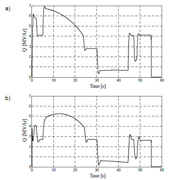
Fig.2 shows the active and reactive power waveforms recorded at the supply point of the hoisting machine during a single cycle of operation. It can be seen that the active power surge during the start-up reaches almost 6 MW, and the reactive power surge exceeds 6.5 MVAr. Such large and relatively fast load changes are difficult to compensate for in an automatic reactive power compensation system without the use of active filters of sufficient power.
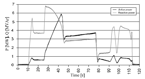
The shape of the waveforms shown in Fig.2 is related to the driving trajectory and the motor load. The shape of the waveforms and values of the reactive power are additionally influenced by the control of the 12-pulse thyristor rectifier. The characteristic shape of the reactive power waveform during the start-up of the hoisting machine indicates the symmetrical control of both 6-pulse rectifiers which are the parts of 12-pulse rectifier supplying the hoisting machine motor.
Control of a 12-pulse rectifier
Fig.3 shows a schematic diagram of a 12-pulse rectifier consisting of two 6-pulse rectifiers connected in series on the DC side.
These 6-pulse rectifiers are supplied from separate converter transformers with appropriate connection groups allowing the voltage on the secondary side to be shifted by an angle of 30°.

Symmetrical (common, simultaneous) control is based on the same thyristors firing angle in both 6-pulse rectifiers, one of which is supplied from a transformer with connection group Y/Δ and the other from a transformer with connection group Y/Y, i.e.

A 12-pulse rectifier controlled in this way generates higher harmonics current of the order of

where: n =1, 2, 3…
The supply current to the 12-pulse rectifier is equal to twice the current drawn by each of the 6-pulse rectifiers, and the fundamental harmonic reactive power drawn by the 12-pulse rectifier is equal to twice the reactive power drawn by each of the compound 6-pulse rectifiers.
In order to reduce the reactive power consumed by the 12-pulse rectifier, an asymmetrical sequential control of the thyristors can be used [8, 10, 14, 15]. The idea of an asymmetrical sequential control of a 12-pulse rectifier is presented in Fig.4.
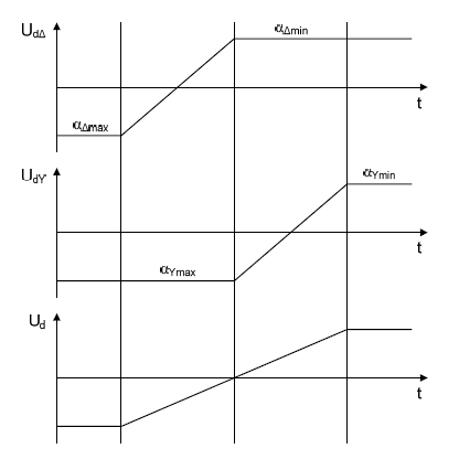
The sequential control consists in firing the thyristors of one of the 6-pulse rectifiers with a fixed angle, and the other 6-pulse rectifier thyristor firing angle is changed to obtain the desired voltage on the DC side. For rectifier operation
or

and for inverter operation

or

In Fig.2 only the rectifier operation of the hoisting machine converter occurred in presented cycle.
The sequential control results in an increase of the current higher harmonics in the grid. A 12-pulse rectifier controlled in this way generates current higher harmonics characteristic of both a 12-pulse and a 6-pulse rectifier with values dependent on instantaneous thyristor firing angles.
The maximum reactive power of the fundamental harmonic is less than twice the maximum reactive power consumed by each 6-pulse rectifier, i.e. less than the maximum reactive power consumed by a rectifier with symmetrical control. In practice, due to the limitation of the minimum and maximum the thyristors firing angle, the asymmetric control allows to reduce the reactive power consumption by about 25% [13].
In high power drive systems, asymmetrical sequential control is often preferable, allowing a reduction in reactive power at the expense of generating additional current higher harmonics, especially of orders 5 and 7.
Simulation researches
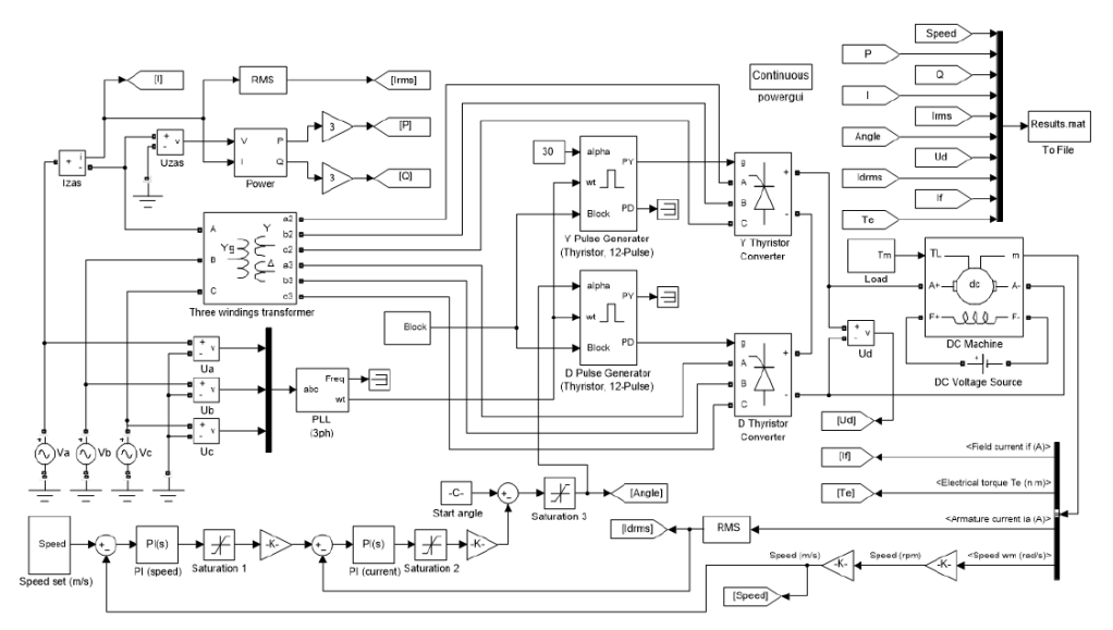
A complete Matlab-Simulink simulation model of a thyristor hoisting machine is presented in [16]. For the presented research the simplified model shown in Fig. 5 was used.
The simplified simulation model does not take into account the reversible operation of the machine. It was assumed that the motor excitation winding was supplied with the rated current. It was also assumed that the drive system will be powered from a stiff power grid. The motor current was limited to the rated value. It was also assumed that the 12-pulse rectifier will operate only in the rectifier operating area, at αY=αmin=30°.
The simulation model in Fig.5 corresponds to the sequential control of the rectifier. For symmetrical control simulations, the Y Pulse Generator block is eliminated, and the signal from the PY output of the D Pulse Generator block is connected to the g inputs of the Y Thyrystor Converter block.
The speed setting is performed in the Speed set block according to the trajectory shown in Fig.6 [13].
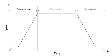
The fixed steady state speed is 16 m/s. During starting and breaking, the maximum speed during entry and exit of the skips from the cams is limited to 1.5 m/s. The acceleration to the fixed speed is 0.8 m/s2, and the deceleration during braking is 1 m/s2.
The simulation experiments were performed for identical working conditions and controller settings in a system with symmetrical and asymmetrical/sequential control of the thyristors in the rectifier. Due to the ratio of the simulation time to the integration step associated with the thyristor switching, the periods of fixed speed driving were shortened. In Fig.7-8 the waveforms of active and reactive power during the cycle of the hoisting machine are shown.
Assuming, based on the measurements in Fig.1, that during an off-duty period of the hoisting machine the average active power of the other loads supplied from the 110/6 kV transformer is 3.5 MW, and the average reactive power is -0.25 MVAr (capacitive reactive power), the waveforms of the power factor tgφ at the secondary side of the supply transformer were determined for both control methods and are presented in Fig.9.
The change in reactive power required to compensate the system for a given power factor tgφ can be determined from the relationship

where: ΔQ – required reactive power change, P, Q – current instantaneous value of active and reactive power at the plant’s supply point, tgφz – set value of power factor at the plant’s supply point.

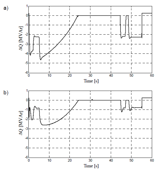
Assuming that the allowable power factor tgφ at the plant’s power supply point should be within the range of 0- 0.4, the waveforms of the reactive power remaining to be compensated after exceeding the allowable range were determined and are presented in Fig.10.
As can be seen from the waveforms obtained from the simulation tests, changing the thyristor control from symmetrical control to sequential control reduces the reactive power consumed by the hoisting machine drive and gives better conditions for the compensation of the plant’s power grid by the automatic reactive power compensation system.
Higher harmonics
The reduction of the reactive power consumed by the rectifier supplying the hoisting machine motor after the change of thyristor control to sequential control is accompanied by the presence of additional higher harmonics of the current consumed by the rectifier.
Based on the rectifier supply current waveform obtained during simulation, an analysis of the higher harmonics of the current drawn by the machine was performed for both control methods. The period of acceleration to a steady fixed speed and steady driving after the transition processes were considered. In Fig.11 the content of characteristic current higher harmonics is shown, and in Fig.12 a comparison of the current THD coefficient is presented. The symbol * denotes the speed during steadystate operation. The content of current higher harmonics at sequential control for different firing angles can also be determined from analytical relations presented in the work [17].
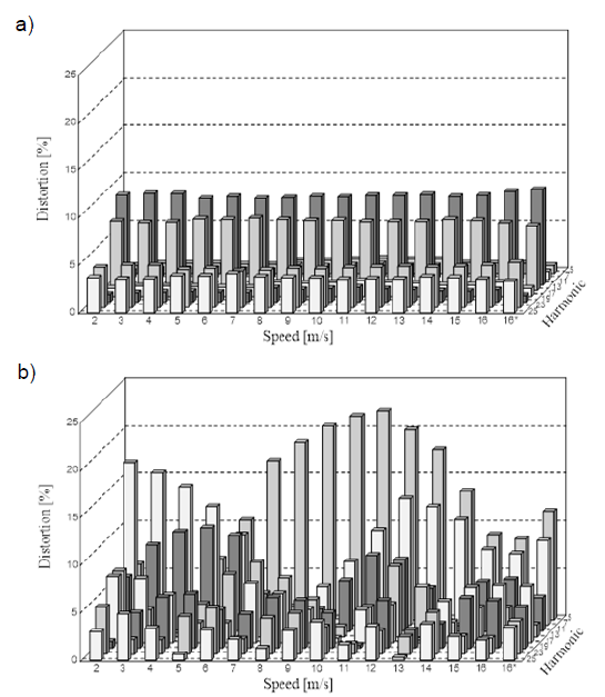

On the basis of the analysis of the content of current higher harmonics, it can be observed that with symmetrical control the 11th harmonic is dominant, and during acceleration, i.e. with the change of the firing angle of the thyristors, the values of individual harmonics and THDi practically do not change.
With sequential control, additional harmonics appear (especially 5 and 7, but also 17 and 19) and their values are variable and depend on the thyristors’ firing angle. The current THD coefficient also changes with the firing angle of the thyristors and is greater than that obtained with symmetrical control over the entire considered range of operation.
Simulation studies were carried out with full symmetry of the supply voltage. Due to the sensitivity of multi-pulse systems to asymmetry or distortion of the supply voltage [12], in practice, in power grids with many unstable high power loads, an increase in the content of higher harmonics above the values determined in the simulations should be expected, as well as the appearance of uncharacteristic harmonics of the 5th and 7th order in symmetrical control. For this reason, passive 5th and 7th, and often also 11th and 13th harmonic filters are used when supplying high power loads, even in systems with symmetrical control [18].
Summary and conclusions
The paper presents a comparative analysis of the impact on the power grid of a 12-pulse rectifier supplying a high power thyristor hoisting machine with two methods of controlling the converter thyristors: symmetrical and sequential (asymmetrical). The influence of the control method on the reactive power consumed by the machine and the content of current higher harmonics was shown.
In Polish underground mines, high power thyristor hoisting machines drives are powered by 12-pulse rectifier systems with symmetrical control. The change to sequential control makes it possible to reduce reactive power surges caused by the machine drive system. This change, however, requires that the passive higher harmonic filters be adapted to the new operating conditions, in particular of the 5th and 7th order, in order not to overload them.
Due to the power quality requirements set by the electricity distributors and the technical aspects related to the influence of thyristor hoisting machines on other devices in the company’s internal power grid, the aim is to reduce their impact on the grid as much as possible. However, economic aspects relating to the cost-effectiveness of the modernisation of systems must also be taken into account.
At present, mining plants pay special attention to the possibility of eliminating or reducing the penalty fees charged by power distributors in connection with failure to meet power quality parameters at the plant supply point. In Poland, penalty charges are mainly related to noncompliance with the contracted power factor tgφ at the point of connection to the power grid. For this reason, great attention is paid to the correct operation of automatic reactive power compensation systems.
Reducing the reactive power surges caused by thyristor hoisting machines significantly improves the ability to maintain the power factor at the plant’s supply point within the permissible range, thus minimising the penalty charges associated with exceeding the power factor required by the power distributor.
REFERENCES
[1] Dixon J., Moran L., Rodriguez J., Domke R.: Reactive Power Compensation Technologies: State-of-Art Review, Proc. of the IEEE. vol.93. no.12, 2005, pp.2144-2164
[2] Igbinovia F. O., Fandi G., Švec J., Müller Z., Tlusty J.: Comparative review of reactive power compensation technologies, 16th International Scientific Conference on Electric Power Engineering (EPE), 2015, pp.2-7, doi: 10.1109/EPE.2015.7161066
[3] Fryze S.: Active, reactive and apparent powers in nonsinusoidal systems (in Polish), Przegląd Elektrotechniczny, no.7/1931, pp.193-203
[4] Ortega J. M. M., Payan M. B., Mitchell C. I.: Power factor correction and harmonic mitigation in industry, Industry Applications Conference, 2000. Conference Record of the 2000 IEEE, Rome, 2000, vol.5, pp.3127-3134, doi: 10.1109/IAS.2000.882612
[5] Balci M. E., Hocaoglu M. H.: Comparison of power definitions for reactive power compensation in nonsinusoidal conditions, 11th International Conference on Harmonics and Quality of Power, 2004, pp.519-524, doi: 10.1109/ICHQP.2004.1409408
[6] Matyjasek Ł., Matyjasek K.: Power factor correction systems for mining hoists with special consideration of STATCOM systems, (in Polish) The Scientific Papers of Faculty of Electrical and Control Engineering Gdańsk University of Technology, vol.67, JDEE Scientific – Technology Conference Power Quality of Electricity Supply – joint responsibility of producers, distributors, consumers and prosumers, 2019, pp.153-157, doi: 10.32016/1.67.31
[7] Pogorelov A. V.: Improving Filter-Compensating Devices in Power Supply Systems of Mine Hoists, 2019 International Multi-Conference on Industrial Engineering and Modern Technologies (FarEastCon), 2019, pp.1-4, doi: 10.1109/FarEastCon.2019.8934157
[8] Ahsan F. M., Chatterjee J. K., Das A.: Operation of a 12-pulse converter in closed loop for controlled P-Q operation, 2006 International Conference on Power Electronic, Drives and Energy Systems, 2006, pp.1-6, doi: 10.1109/PEDES.2006.344236
[9] Po-Tai Cheng, Bhattacharya S., Divan D. M.: Application of dominant harmonic active filter system with 12 pulse nonlinear loads, IEEE Transactions on Power Delivery, vol.14, no.2, pp.642-647, April 1999, doi: 10.1109/61.754112
[10] Modi P.S., Joshi S. K.: New combined Hybrid active filter for twelve pulse converter operating under asymmetrical operation, AUPEC 2011, 2011, pp.1-6
[11] Płatek T., Cichomski P., Baranecki A., Biernacik T.: Hybrid system for power factor passive power compensation for supply system of hoisting machine in coal mine, (in Polish), Przegląd Elektrotechniczny, no.10/2014, pp.236-241, doi: 10.12915/pe.2014.10.56
[12] Gała M., Jagieła K., Kępiński M., Rak J.: Influence of high power DC converters drives on operating parameters of induction machines, (In Polish) Zeszyty Problemowe – Maszyny Elektryczne, no.76/2007, KOMEL, 2007, pp.35-40
[13] Siostrzonek T., Chmielowiec K., Piątek K., Dutka M. Firlit A.: The use of multi-pulse systems in the power supply of hoisting machine drives to improve voltage parameters in mining plants, 2020 12th International Conference and Exhibition on Electrical Power Quality and Utilisation- (EPQU), 2020, pp.1-6,
doi: 10.1109/EPQU50182.2020.9220301
[14] Das A., Chatterjee J. K., Gaja A. K.: Asymmetrical firing of 12-pulse converter for controlled P-Q operation using PIC microcontroller, 2006 IEEE Power India Conference, 2006, pp.5 doi: 10.1109/POWERI.2006.1632602
[15] Modi P. S., Joshi S. K.: Effect of source inductance on controlled var operation of 12- pulse converter, 2009 International Conference on Control, Automation, Communication and Energy Conservation, 2009, pp.1-7
[16] Pogorelov A. V.: Simulation modeling of DC electric drive for mine hoist, IOP Conference Series: Materials Science and Engineering, 2019, vol.643, pp.1-7, doi: 10.1088/1757-899x/643/1/012037
[17] Hamad M. S., Masoud M. I., Massoud A. M., Finney S. J., Williams B. W.: A new power locus for the p-q operation of series connected 12-pulse current source controlled converters, 2008 IEEE Power Electronics Specialists Conference, 2008, pp.2264-2270, doi: 10.1109/PESC.2008.4592278
[18] Hyla M.: Higher harmonics filtration in the power supply system of thyristor hoisting machine of shaft transport in a mining plant, Przegląd Elektrotechniczny, no.5/2022, pp.43-48, doi: 10.15199/48.2022.05.08
Autor: dr inż. Marian Hyla, Silesian University of Technology, Faculty of Electrical Engineering, Department of Power Electronics, Electrical Drives and Robotics, ul. B. Krzywoustego 2, 44-100 Gliwice, Poland, e-mail: marian.hyla@polsl.pl
Source & Publisher Item Identifier: PRZEGLĄD ELEKTROTECHNICZNY, ISSN 0033-2097, R. 98 NR 9/2022. doi:10.15199/48.2022.09.11
