Published by Alla Eddine TOUBAL MAAMAR, M’hamed HELAIMI, Rachid TALEB, Electrical Engineering Department, Hassiba Benbouali University, LGEER Laboratory, Chlef, Algeria
Abstract. In this study, the analysis, simulation and realization of direct current to alternating current multilevel inverter are discussed. Inverter operation with the high-frequency mode is evaluated and tested for the validation of the topology. This inverter type will be used in an induction heating system or other industrial applications need high-frequency, periodic and alternating signals. The control signals of electronic switches are implemented via an open-source board, Arduino, composed of an Atmega2560 microcontroller. Simulation with MATLAB/Simulink environments and experimental results are presented, comparatively, for a comparison.
Streszczenie. W artykule zaprezentowano symulację, analizę I eksperymentalną weryfikację przekształtnika. DC/AC. Ten typ przekształtnika może być zastosowany w nagrzewaniu elektrycznym lub innych zastosowaniach wymagających prądu wcz. Analiza, symulacja I eksperymentalna weryfikacja wielopoziomowego przekształtnika DC/AC wysokiej częstotliwości..
Keywords: Power Electronic, Multilevel Inverter, High-frequency Signals, MATLAB/Simulink
Słowa kluczowe: przekształtnik DC/AC, przekształtnik wysokoczęstotliwościowy.
Introduction
A most of renewable energies source like solar energy produce direct current, the Direct current (DC) must be converted into an alternating current (AC), because most of the devices used in our daily lives use it, the circuit which converts DC power into desired output voltage, frequency, and AC power form is called as Inverter [1]. If several DC voltage sources are used as an input or special topology of an inverter is implemented, a desired output voltage stages can be obtained, the inverter will be named multilevel inverter. There are many research and proposed topologies of the conventional multilevel inverter [2], [3], capacitor clamped inverter [4], diode clamped inverter [5] and the cascaded multilevel inverter is the most popular inverter, is used for many applications [6].
The main aims of this research are to analysis and simulation of High-Frequency DC/AC hybrid Five-level Inverter properties with MATLAB/Simulink, this type of converter is widely used in standby power supplies, induction heating, and induction motor drives [7]. A Realization and test of the presented topology are important steps for validation of obtained results.
The paper is organized as follows: In the second Section, The analysis of the hybrid topology of Five-level inverter operation have been discussed, the simulation and realization results are presented in the later sections. Eventually, conclusions are given.
Analysis of the DC/AC Multilevel Inverter Operation
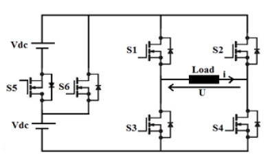
Fig. 1, showing the topology of a five-level inverter [8], this topology consists of less number of switches when to be compared with the conventional topology of a five-level cascaded H-bridge inverter. The presented topology consists of two separate DC sources and six semiconductor devices switches. By switching the semiconductor devices at the appropriate firing angles, we can obtain the full cycle of the phase voltage shown in Fig.2.
Inverter topology is composed of H-bridge inverter with two switching cells (S1, S3 and S2, S4) and two extra switches (S5, S6), depending on the states of the electronic switches, five operating sequences can be distinguished during a switching period T.
Sequence 1: (U = 0), the switch S6 is closed and switches S1, S2, S3, S4, S5 are opened. Sequence 2: (U= +V), the switches S1, S4 are closed and switches S2, S3, S5, S6 are opened.
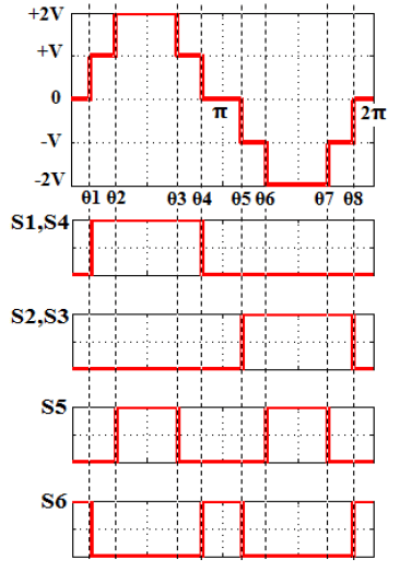
Sequence 3: (U= +2V), the switches S1, S4, S5 are closed and switches S2, S3, S6 are opened.
Sequence 4: (U= -V), the switches S2, S3 are closed and switches S1, S4, S5, S6 are opened.
Sequence 5: (U= -2V), the switches S2, S3, S5 are closed and switches S1, S4, S6 are opened.
Simulation of a Five-level Inverter
Simulation of the five-level inverter is done in MATLAB environment (SIM/POWER/SYSTEMS). The simulated circuit is a MOSFET based resistor Load, R=10 ohm.

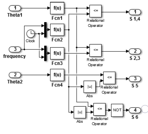
The functions of the switches control are determined by the following relationships.
Fcn1= sin((u(1)2pi)/360)
Fcn2= sin(u(1)2piu(2))
Fcn3= sin((u(1)2piu(2))+pi)
Fcn4= sin((u(1)2pi)/360)
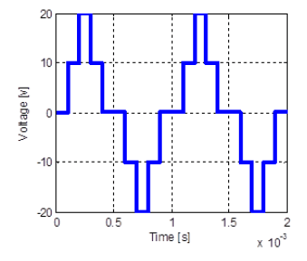
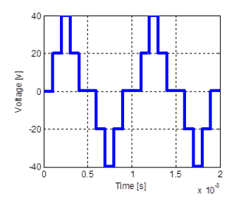
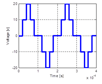
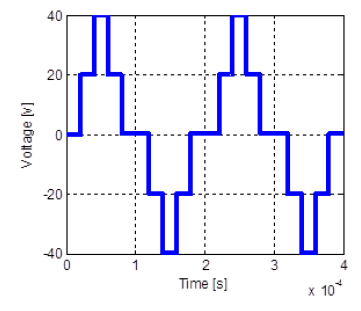
“Fig. 5”, “Fig. 6”, “Fig. 7”, “Fig. 8”, shows the output voltages of resistor load using MATLAB/Simulink with different frequency, 1 [KHz], 5 [KHz], and dc =10 [v], dc =20 [v].
Arduino ATmega2560 Microcontroller and Digital PWM signals generations
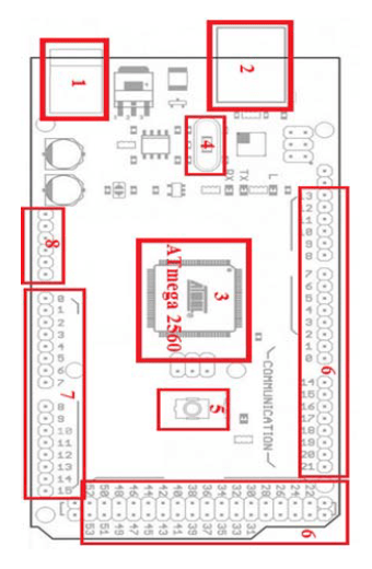
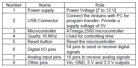
Arduino is a printed circuit, consisting of several electronic components and a microcontroller to receive, analyze and produce electrical signals, the main advantage of the Arduino technology is an open-source platform and you can directly load the programs into the device without the need of a hardware programmer to burn the program. Arduino board based on an ATmega2560 microcontroller is shown in the Fig.9. It consists of 54 pins, Where 14 digital inputs/outputs pins and 6 analogue inputs/outputs pins, a 16MHz clock, has 256 KB of flash memory, 8 KB of RAM and 4 KB of EEPROM [9], [10].
In several applications, which are powered by inverters, it is necessary to control the output voltage, PWM as one of the most efficient techniques to vary the voltage gain. Modern microcontrollers (PIC Microcontroller, ARM Cortex M, PIC, ARDUINO UNO card, ARDUINO ATmega2560 card, …etc.) all have peripherals or pins dedicated specifically to PWM generation. The method of this work has programmed the TIMER of the ARDUINO ATmega2560 card to transform it into a digital PWM generator, the principle is to create a digital configured signal of frequency and duty cycle. A timer is a register located in the microcontroller that is incremented or decremented each time it receives a pulse from a clock signal. Therefore, a timer is a counter, capable of counting the time that elapses, hence its name counter timer.
The ATmega 2560 microcontroller has one 8-bit counter timer numbered 0 and four 16-bit counter timers numbered 1, 3, 4 and 5. The Timer configured with two control registers TCCRnA and TCCRnB. The clock used is the main clock of the Arduino ATmega 2560, which has a frequency of 16 MHz. The selection of the clock mode operation is made on bits 2, 1 and 0 of the TCCRnB register. To produce the waveform signal, it is necessary to use the Timer in a wave generator mode. The main generator modes are Normal Mode, Fast PWM Mode, and Phase Correct PWM Mode. The selection is made with the 4 bits: WGMn0, WGMn1, WGMn2 and WGMn3 (Waveform Generation Mode), the first two are bits 0 and 1 of the TCCRnA register; the last two are bits 2 and 3 of the TCCRnB register. The counter also includes OCRnX register (Output Compare Register) which is compared to the TCNT register to trigger various actions. This counter used to configure the duty cycle of the PWM signals[9], [11].
Table 1. Name and Role of Arduino components
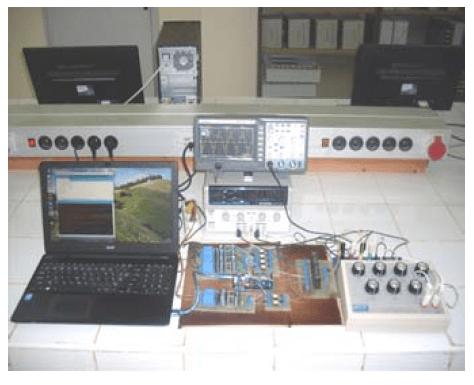
Realization of a Five-level Inverter
Fig. 10, Shows the experimental prototype of the five-level inverter, consists of six MOSFET switches IRF 640 controlled by driver circuits with TLP 250 optocoupler, two power supplies (Vdc). The control signals have been implemented using Arduino ATmega2560 Microcontroller and PC with open source software (Arduino IDE).
“Fig. 11”, “Fig. 12”, “Fig. 13”, “Fig. 14”, shows the experimental phase voltage of the five-level inverter with different frequency, 1 [KHz], 5 [KHz], and power voltages, 10 [v], 20 [v].
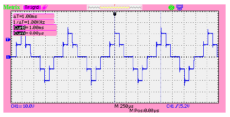
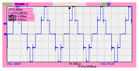
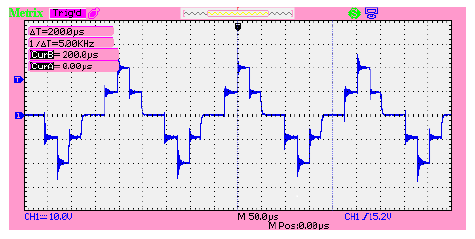
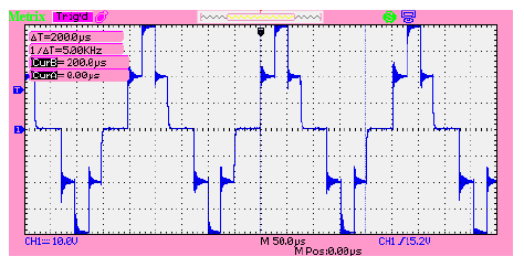
The simulation results of the 5-level output voltage are presented in “Fig. 5”, “Fig. 6”, “Fig. 7”, “Fig. 8”, and experimentally validated, the experimental prototype and results of the output voltage waveforms generated by inverter are presented in “Fig. 11”, “Fig. 12”, “Fig. 13”, “Fig.14”, There are a small shifts between the two form of results (simulation and realisation), but generally, the obtained results show the good concordance existing between the simulation model and the real system, the small shift because of the electrical perturbations of electronic components. The output power of the five-level inverter can be controlled by adjusting the frequency or the duty cycle of the switches.
Conclusion
The analysis, simulation and realization of a hybrid five-level inverter are discussed in this paper. The effectiveness of the analysis is verified by the obtained results.
The high-frequency DC/AC inverter has been chosen because our future purpose is the study of induction heating, and the frequency is the main physical parameter of this type of converters.
The results obtained are satisfactory because the simulation model of a multilevel inverter with Matlab is validating experimentally using Arduino ATmega2560 microcontroller. This work opens new ways for future research with other topologies, other electronics devices controllers like the pic microcontroller or FPGA and levels of the inverter can be increased.
REFERENCES
[1] Rajkumar M., Manoharan P.S., Modeling and Simulation of Five-level Five-phase Voltage Source Inverter for Photovoltaic Systems, Przeglad Elektrotechniczny, 10 (2013), 237-241
[2] Babaei E., Alilu S., and Laali S., A New General Topology for Cascaded Multilevel Inverters With Reduced Number of Components Based on Developed H-Bridge, IEEE Trans. Ind. Electron., 61(2014), NO. 8, 3932-3939
[3] Gupta K. K., Ranjan A., Bhatnagar P., Sahu L. K., Jain S., Multilevel Inverter Topologies With Reduced Device Count: A Review, IEEE Trans. Power Electron., 31(2016), No. 1,135-151
[4] Raman S. R., Cheng K. W. E., Ye Y., Multi-Input Switched- Capacitor Multilevel Inverter for High-Frequency AC Power Distribution, IEEE Trans. Power Electron., 33(2018), No. 7, 5937-5948
[5] Shi S., Wang X., Zheng S., Zhang Y., Lu D., A New Diode- Clamped Multilevel Inverter With Balance Voltages of DC Capacitors, IEEE Trans. on Energy Conversion, 33 (2018), No.4, 2220-2228
[6] Ebrahimi J., Babaei E., Gharehpetian G. B., A New Topology of Cascaded Multilevel Converters With Reduced Number of Components for High-Voltage Applications, IEEE Trans. Power Electron., 26 (2011), No. 11, 3109-3118
[7] Waradzyn Z., SKAŁA A., ŚWIĄTEK B., KLEMPKA, KIEROŃSKI R., ZVS single-switch inverter for induction heating optimum operation, Przeglad Elektrotechniczny, 2 (2014), 32- 35
[8] El-Naggar K., Abdelhamid T. H.,Selective harmonic elimination of new family of multilevel inverters using genetic algorithms, Energy Conversion and Management, 49 (2008), nr 1, 89–95
[9] Montironi, M.A., Qian, B., Cheng, H.H., Development and application of the ChArduino toolkit for teaching how to program Arduino boards through the C/C++ interpreter Ch, Comput Appl Eng Educ, 25 (2017), 1053– 1065
[10] Arduino.cc, Arduino Mega 2560, Accessed 03/11/2019. Available: https://store.arduino.cc/arduino-mega-2560-rev3
[11] Atmel-Datasheet, 02/2014. Accessed 03/11/2019. Available: http://ww1.microchip.com/downloads/en/DeviceDoc/Atmel-2549-8-bit-AVR-Microcontroller-ATmega640-1280-1281-2560-2561_datasheet.pdf
Authors: Alla Eddine, TOUBAL MAAMAR, a.toubalmaamar@univchlef. dz (corresponding author); M’hamed, HELAIMI, E-mail: m.helaimi@univ-chlef.dz; Rachid, TALEB, E-mail: r.taleb@univchlef. dz; authors affiliation: Electrical Engineering Department, Hassiba Benbouali University of Chlef, Laboratoire Génie Electrique et Energies Renouvelables (LGEER), BP. 78C, Ouled Fares 02180, Chlef, Algeria.
Source & Publisher Item Identifier: PRZEGLĄD ELEKTROTECHNICZNY, ISSN 0033-2097, R. 96 NR 8/2020. doi:10.15199/48.2020.08.03
