Published by Łukasz KOLIMAS, Sebastian ŁAPCZYŃSKI, Michał SZULBORSKI, Warsaw University of Technology, Electrical Power Engineering Institute
Abstract. The requirements for high-current circuits, contact systems, switchboards and electrical apparatuses differ from the typical requirements for devices with a low current load, not only because those are more complex, but also because new requirements arise due to the fact that the size of the designed devices and power systems is constantly growing, both their breadth and diversity.
Streszczenie. Wymagania stawiane wielkoprądowym torom, układom stykowym, rozdzielnicom i aparatom elektryczny, różnią się od typowych wymagań dla urządzeń o niewielkim obciążeniu prądowym nie tylko tym, że są trudniejsze, ale pojawiają się wymagania nowe wynikające z tego, że ustawicznie rośnie wielkość projektowanych urządzeń i systemów elektroenergetycznych, ich rozległość i różnorodność. Symulacja parametrów elektrycznych torów wielko prądowych
Słowa kluczowe: projektowanie, rozkład temperatury, rozdzielnice i aparaty elektryczne, siły elektrodynamiczne.
Keywords: design, temperature distribution, electrical switchboards and apparatuses, electrodynamic forces.
Introduction
Due to the increasing threats posed to human health, life and to devices e.g. switchgears, short-circuit currents have been investigated for electrodynamic forces. How important it is to build simulation models of busbars and distribution circuits can be proved, inter alia, in publications [1-6]. Based on the thermal results, the authors calculate the dynamic stability of the EIPB (Enclosed Isolated Phase Busbar) to analyze the electrodynamic forces under short-circuit conditions. The 2-D model was used for this purpose. In our discussion, the 3-D model is presented considering all electromechanical hazards (stresses of supporting insulators, natural frequency of the system and electrodynamic forces). Many scientists have studied the thermal stability of EIPB at short-circuit current conditions [7-8] and proposed a method of calculating the bus conductor temperature using the heat network analysis. Methodology revolved around analysis of the contact resistance concerning the busbar parts and calculations of the temperature rise generated by the resistance [10-13]. The experiment was set to check the reliability of busbar contacts and to predict the contact state based on theoretical models. The effects of electrodynamic forces, temperature rise and other factors such as mechanical strength were taken into consideration and the effect of a short-circuit condition on the bus cable was analyzed. However, most of these methods note the exceedingly small size of the rails, which are not longer than 5 meters, the test object is small and has a simple structure. In this work, the validation of the analytical model using the 3-D model of busbars with contacts is proposed. Due to the complex structure of the power system network, actual EIPBs are often large with complex structures and it is difficult to directly calculate the dynamic stability. The finally presented FEM model can be used for insulated busbars in various environments. On this basis, the design and implementation of low-voltage switchgear was successfully carried out. The presented results enable the correct selection of busbars not only from the point of view of current carrying capacity, but also electrodynamic capacity. A solution enabling the validation of analytical calculations, the implementation of different, often complicated circuits in relation to the calculations of simple rectangular or circular current circuits were presented. The model enables the determination of values for scientific and engineering calculations. It has been shown that the selection of supply and receiving current circuits can be performed not only from the point of current-carrying capacity. Not only the skin effect was taken into account, but also the current displacement and the natural frequency of the system [14- 21].
Analytical calculations
Of course, in the case of remarkably simple current circuits (in terms of shape and cross-section – rectangular, circular), it is possible to use analytical dependencies. This chapter presents the basic equations concerning the determination of mechanical and electrical quantities relating to high-current circuits.
Mechanical vibrations in busbar systems
Busbars exposed to electrodynamic forces are also exposed to mechanical vibrations that occur with this phenomenon. The amplitude of these vibrations depends on many factors, which include, among the others: the way the busbars are placed, the type of material of which those are made of and the number of installed insulation brackets. The most undesirable case occurs when the natural frequency of the busbars coincides with the frequency of changes in forces affecting their system. For this reason, the natural frequency of the busbar should be offset from the frequency of mechanical excitations having source in electrodynamic forces. The most dangerous case may occur during the appearance of resonance characterized by the system’s own vibrations equal to:
where: fo is system natural vibration; f is frequency of current change; 2f is frequency of changes in periodic (non-disappearing) components.
In order to determine the permissible natural frequency of the busbar system the following dependency (2) shall be used. Furthermore, it is obligatory to choose the frequency value that is outside the following interval:

Properly determined busbar natural frequency should be outside the specified incorrect ranges. In case the calculated frequency does not correspond to the above assumptions, the system parameters should be adjusted to offset the natural frequency of the tested busbar from the resonance frequency. t is possible to determine the natural frequencies considering the coefficients responsible for the special features concerning the construction of the analyzed current circuits. In this case the following formula is used:
where: foo is a natural frequency of a simplified system: c1 is a coefficient that allows to take into account the influence of spacers used to connect individual rails in a multi-strip system: c2, c3 is a factor that allows stiffness, weight and cable routing to be taken into account.
Short-circuit currents calculations
In order to determine the circuit parameters that allow safe operating conditions to be maintained during a short circuit, calculations of electrodynamic forces should be made assuming the most unfavorable short circuit scenario associated with the currents with the highest possible intensity. In Poland, such conditions usually occur during a three-phase symmetrical short circuit and in this case basic patterns have been presented: the consistent component of the initial current I can be calculated from the formula:

where: Un is rated voltage; k is ratio of the voltage ratio before the short circuit to the rated voltage Un ; ΔZ is a short-circuit impedance for three-phase short circuit while ΔZ = 0.
Based on the determined value, the so-called initial current can be calculated. Initial current is described as the effective value of the periodic component being part of the short-circuit current at the time of the occurrence of the short-circuit, which is equal to:
where: m is a current factor for a three-phase short circuit. Assuming value m = 1 and k = 1.1, the value of the initial current can be expressed as:
Due to the occurrence of a non-periodic component, the peak short-circuit current can reach much higher values than the peak value of the periodic component. If the short circuit occurs when voltage passes through zero (for phase angle voltage equal to 0 or p), the peak value of the short-circuit current reaches the highest possible value and is called the surge current. The surge current is the maximum achievable short-circuit current used in electrodynamic calculations. Spoken value can be determined from the following formula, considering the calculated initial current value:

where: Ip is initial current value; ku is a surge factor.
When determining electrodynamic interactions at three-phase faults, two cases can be distinguished taking into account or omitting the fact of non-periodic components. If the influence of non-periodic components is omitted, and assuming that the individual phase currents are directed in accordance, they can be described by the following formulas:
To correctly determine the value of mutual interaction of electrodynamic forces, the largest possible values of forces should be found, which in this case will occur for the maximum value of the multiplication of both currents. Therefore, in a flat single three-pole system, where the external current circuits are arranged symmetrically with respect to the middle busbar, the electrodynamic forces acting on individual conductors can be described by the following equations:

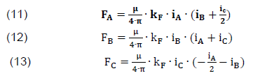
After proper substitution of the above formulas, the equation is obtained that allows to determine the value of electrodynamic forces acting on the external current circuits through which current iA flows:

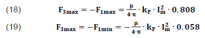
To obtain the maximum value of force it is necessary to determine the extremes for the function f(ωt):

After substitution, the below equations are derived:

The maximum values of electrodynamic forces for the external current circuit through which the current iC flows are exactly the same as for the conductive busbar iA and could be determined from the following dependencies:
The value of electrodynamic forces acting on the center busbar of the system presents slightly different. After substituting the current formulas, the equation is obtained:

After determining the maximum values, the above dependency can be described as:

Numerical calculations
In low voltage switchgears, small insulation gaps between the busbars of individual phases are sufficient, and the level of short-circuit currents is similar to that in high voltage switchgears. The problem of electrodynamic stresses acting on busbars is therefore more pronounced in the former, although the mitigating circumstance is the smaller distances between the busbar fastening points. The rules for dimensioning rigid rails regarding electrodynamic loads in short-circuit conditions are specified in the standard (IEC 865-1 Short-circuit currents – Calculation of effects). The calculations are quite complex and based on such simplifications that their practical usefulness is not enough. When developing the concept of a new series of switchgears, those serve as the basis for initial design solutions, which are then verified in the short-circuit laboratory. Multicore cables and other insulated conductors, correctly selected for their thermal short-circuit endurance, generally also withstand the electrodynamic forces associated with the flow of short-circuit current. Due to the small thickness of the insulation, and therefore smaller distances between the axes of the conductors, the electrodynamic forces in cables and other low-voltage devices – with the same value of short-circuit current – are greater than in high-voltage cables. Checking may be needed in the case of extremely high short-circuit currents (over 60 kA) that are switched off in a short time (less than 20 ms), but without any limiting effect, i.e. with passing the expected value of the surge from short-circuit current.
Electrodynamic exposures must also be considered while choosing the construction principle and technique of assembly of the heads and cable joints.
The finite element method is a necessary and versatile – often used numerical method that can clearly optimize the process of designing electrical devices. The article proposes the use of FEM tools, such as SolidWorks and ANSYS, to support the design and modeling of high-current circuits and their contacts. The models were simulated taking emphasis on the electrodynamic forces analysis caused by the short-circuit current flow. At the model stage, physical phenomena important not only from the point of view of the mechanical properties, but also from the view of electrical engineering were determined. This procedure is unbelievably valuable during design/engineering work. That concerns mostly the material economy. Figure 1 shows a model of the current circuits of an exemplary low voltage switchgear with contacts. The model was made in the SolidWorks program.

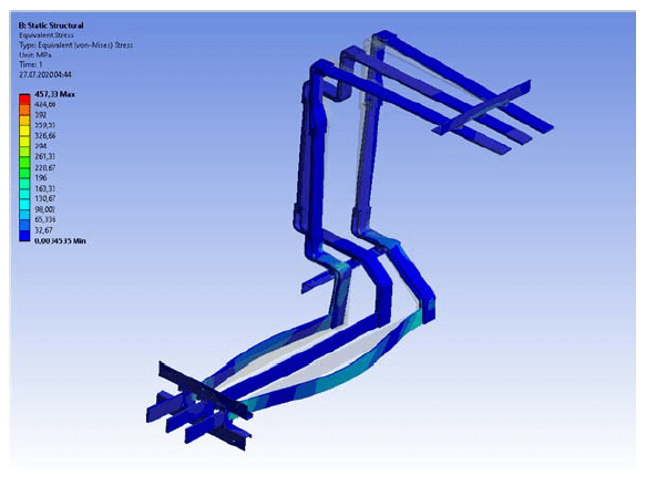
The model prepared in this way was subjected to the full modeling process in the ANSYS program. The boundary conditions and the correct exposure of the results were considered. Figure 2 shows the results of reduced stresses caused by the flow of a short-circuit current of 50 kA.
A series of numerical calculations were made to determine the electrodynamic force, and thus the maximum mechanical stresses. The simulations were made for a three-phase short-circuit current with the waveforms shown in Figure 4.


The presented results clearly show that it is worth stabilizing current circuits with support insulators. Despite the high electrodynamic forces (power supply lines), the mechanical stresses ought to be stabilized on the receiving lines. The risk of vibrations transmission to the supply devices is reduced, which is especially important for a rigid connection.
Summary
This work concerns building the FEM models that fully and faithfully reproduce real-world conditions. The given approach is invaluable when it comes to modeling electrical apparatuses. The selected approach was to use FEM tools to design not only arc chambers, contact systems but also high-current circuits. However, the optimal capabilities of the tools to which they are dedicated were used to obtain a valuable and complete picture of the modeled object. Indeed, it has been achieved. The presented model, as well as the procedure, have been verified by empirical studies that confirm the rightness of such proceedings. An important feature resulting from this work is the possibility of reconstructing models of designed objects and in the case of structural changes, avoiding expensive and time-consuming laboratory tests or at least reduce their costs. This approach is correct in view of the current trend to reduce time and costs in the design and manufacture process of electrical equipment. Optimization can be applied to existing solutions with the proposed procedure. Such a process can not only increase user safety/service quality, but also reduce material consumption, positively influencing the environment. In addition, FEM modeling can be used to design apparatuses for various conditions, voltage ranges and applications. The above gives great opportunities for safe, fast, and highly economical creation of new trends and solutions in electrical engineering. Of course, the disadvantage of FEM modeling is still the need to conduct experimental tests. More complex solutions may generate additional errors that often lead to inaccuracies in the obtained measurement series during simulation. This is especially expected when establishing boundary conditions. Nevertheless, it is worth using the proposed design tool.
REFERENCES
[1] Bini R., Galletti B., Iordanidis A., Schwinne M., 1st International Conference on Electric Power Equipment – Switching Technology – Xi’an – China, 2011, pp. 375-378
[2] Dhotre M.T., Ye1 X., Seeger M., Schwinne M., Kotilainen S., CFD Simulation and Prediction of Breakdown Voltage in High Voltage Circuit Breakers, 2017 Electrical Insulation Conference (EIC), Baltimore, MD, USA, 11-14 June 2017
[3] Jiaxin Y., Yang W., Lei W., Xiaoyu L., Huimin L., Longqing B., Thermal Dynamic Stability Analysis for the Enclosed Isolated – Phase Bus Bar Based on the Subsegment Calculation Model, IEEE Transactions on Components, Packaging and Manufacturing Technology, vol. 8, no. 4, April 2018, pp. 626-634
[4] Williams D.M., Human factors affecting bolted busbar reliability, in Proc. IEEE 62nd Holm Conf. Elect. Contacts (Holm), Clearwater Beach, FL, USA, Oct. 2016, pp. 86–93, October 2016
[5] Yang J., Y. Liu, D. Hu, B. Wu, Li J., Transient vibration study of GIS bus based on FEM, in Proc. IEEE PES Asia–Pacific Power Energy Eng. Conf. (APPEEC), Xi’an, China, pp. 1092–1095, October 2016
[6] Triantafyllidis D.G., Dokopoulos P.S., Labridis D.P., Parametric short-circuit force analysis of three-phase busbars-a fully automated finite element approach, IEEE Trans. Power Del., vol. 18, no. 2, pp. 531–537, April 2003
[7] Yang J., Liu Y., Hu D., B., Wu, Che B., Li J., Transient electromagnetic force analysis of GIS bus based on FEM, in Proc. Int. Conf. Condition Monitor. Diagnosis (CMD), Xi’an, China, pp. 554–557, September 2016
[8] Guan X., Shu N., Electromagnetic field and force analysis of threephase enclosure type GIS bus capsule, in Proc. IEEE PES T&D Conf. Expo., Chicago, IL, USA, pp. 1–4, April 2014
[9] Kolimas Ł., Łapczyński S., Szulborski M., Tulip contacts: experimental studies of electrical contacts in dynamic layout with the use of FEM software, International Journal of Electrical Engineering Education, vol. I, pp. 1-4, 2019, Early Access: https://doi.org/10.1177/0020720919891069
[10] Kolimas Ł., Łapczyński S., Szulborski M., Świetlik M., Low Voltage Modular Circuit Breakers: FEM Employment for Modelling of Arc Chambers, Bulletin of the Polish Academy of Sciences-Technical Sciences, vol. 68, no. 1, pp. 61-70, 2020
[11] Kolimas Ł., Łapczyński S., Currents of contact welding in a static layout: A laboratory exercise, International Journal of Electrical Engineering Education, I, ISSN 0020-7209, 2019, Early Access: https://doi.org/10.1177/0020720919840986
[12] Kolimas Ł., Łapczyński S., Szulborski M., Drogosz M., Kozarek Ł., Kędziora B., Wiśniewski Ł., Bieńkowski K., Simulations and Tests of a KRET Aerospace Penetrator, Energies, ISSN 1996-
1073, pp. 1-23, 2020
[13] Rumpler C., Stammberger H., Zacharias A., Low-voltage arc simulation with out-gassing polymers”, in Proc. IEEE 57th Holm Conf. Electr. Contacts, 2011, September, pp. 1–8
[14] Ryzhov V.V., Molokanov O.N., Dergachev P.A., Vedechenkov N,A,, Kurbatova E.P., Kurbatov P.A., Simulation of the Low – Voltage DC Arc, Intenational Youth Conference on Radio Electronics, Electrical and Power Engineering (REEPE), 14-15 March 2019, Russia
[15] Bini R., Basse N.T, Seeger M., Arc-induced Turbulent Mixing in a Circuit Breaker Model, J. Phys D Appl Phys 44, vol. 2., 2011
[16] Basse N.T., Bini R., Seeger M., Measured turbulent mixing in a small-scale circuit breaker model, Appl. Optics, vol. 48, no. 32, 2009, pp. 6381-6391
[17] Incropera F.P., DeWitt D.P., Bergman T.L, Lavine A.S., Introduction to Heat Transfer, 5th ed. Hoboken, NJ, 2006, USA: Wiley
[18] Muller P.T., Macroscopic electro thermal simulation of contact resistances, Bachelor thesis, RWTH, 2016, Aachen, Germany
[19] Bini R., Basse N.T, Seeger M., Arc-induced Turbulent Mixing in a Circuit Breaker Model, J. Phys D Appl Phys 44, vol. 2., 2011
[20] Kolimas Ł., Łapczyński S., Szulborski M., Bieńkowski K., Kozarek Ł., Birek K, Control System and Measurements of Coil Actuators Parameters for Magnetomotive Micropump Concept, Bulletin of the Polish Academy of Sciences-Technical Sciences, vol. 68, no. 4, pp. 893-901, 2020.
[21] Daszczyński T., Pochanke Z., Kolimas Ł., Uncertainty of the Characteristics of Electrical Devices Based on the Measurements of the Time-current Characteristics of MV Fuses, Bulletin of the Polish Academy of Sciences-Technical Sciences, vol. 68, no. 4, pp. 751-757, 2020.
Authors: dr inż. Łukasz Kolimas, Politechnika Warszawska, Instytut Elektroenergetyki, ul. Koszykowa 75, 00-662 Warszawa, Email: lukasz.kolimas@ien.pw.edu.pl; mgr inż. Sebastian Łapczyński, Politechnika Warszawska, Instytut Elektroenergetyki, ul. Koszykowa 75, 00-662 Warszawa, E-mail: seb.lapczynski@gmail.com; mgr inż. Michał Szulborski, Politechnika Warszawska, Instytut Elektroenergetyki, ul. Koszykowa 75, 00-662 Warszawa, E-mail: mm.szulborski@gmail.com.
Source & Publisher Item Identifier: PRZEGLĄD ELEKTROTECHNICZNY, ISSN 0033-2097, R. 96 NR 11/2020. doi:10.15199/48.2020.11.37
