Published by Stanislaw CZAPP1, Filip RATKOWSKI1, 2, Gdańsk University of Technology (1), Research & Development Center, Eltel Networks Energetyka SA (2)
Abstract. One of the factors affecting current-carrying capacity of underground power cables is the thermal resistivity of soil. Its value in the close proximity of the cable is the most important, and for this reason, in some cases, the local soil is replaced with an another soil type or with a cements and mixture. The thermal resistivity of the soil is strongly affected by moisture, and in the case of a cement-sand mixture – as tested by the authors – also by this mixture initial water content. The paper presents results of investigation of soil moisture influence on the soil thermal resistivity, and an analysis of the current-carrying capacity of a low-voltage power cable for various soil parameters, in particular its part directly surrounding the cable.
Streszczenie. Jednym z czynników wpływających na obciążalność prądową długotrwałą kabli ułożonych w ziemi jest rezystywność cieplna gruntu. Największe znaczenie mają parametry gruntu znajdującego się w bezpośrednim sąsiedztwie kabla i z tego powodu grunt rodzimy zastępuje się innym lub mieszaniną cementowo-piaskową. Na rezystywność cieplną gruntu duży wpływ ma wilgotność, a w przypadku mieszaniny cementowopiaskowej – jak wynika z badań autorów – także zawartość początkowa wody w tej mieszaninie. W artykule przedstawiono wyniki badań wpływu wilgotności gruntu na jego rezystywność cieplną oraz analizę obciążalności prądowej długotrwałej kabla niskiego napięcia dla różnych parametrów gruntu, w szczególności gruntu w bezpośrednim sąsiedztwie kabla. (Wpływ wilgotności gruntu na obciążalność prądową długotrwałą kabli elektroenergetycznych niskiego napięcia).
Keywords: current-carrying capacity, power cables, soil thermal parameters.
Słowa kluczowe: obciążalność prądowa długotrwała, kable elektroenergetyczne, parametry cieplne gruntu.
Introduction
Power cables are mainly installed in the ground, and parameters of the soil as well as additional cables equipment, e.g. a cable duct, significantly influence power cables current-carrying capacity [1-7]. This current-carrying capacity also depends on the position of buried power cables [8]. Moreover, sections of cables may be exposed to external sources of heat [9, 10], what should be taken into account during cables selection and it is very important in terms of reliability of supply [11].
Basic recommendations for calculation of power cables current-carrying capacity Iz are included in standards IEC 60287-1-1 [12] and IEC 60287-2-1 [13]. According to these standards, for AC power cables the capacity Iz can be calculated as follows:
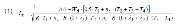
where:
Iz – current-carrying capacity of a power cable, A,
ΔΘ – permissible temperature rise of the conductor above ambient temperature, K,
Wd – dielectric losses per unit length per phase, W/m,
T1 – thermal resistance per core between the conductor and sheath, (K.m)/W,
T2 – thermal resistance between the sheath and armour, (K.m)/W,
T3 – thermal resistance of external serving of the cable (e.g. PVC sheath), (K.m)/W,
T4 – external thermal resistance of surrounding medium, e.g. soil, (K.m)/W,
nc – number of conductors in a cable, -,
R – AC current resistance of a conductor at its maximum operating temperature, Ω/m,
λ1 – ratio of the total losses in metallic sheaths to the total conductor losses, -,
λ2 – ratio of the total losses in metallic armour to the total conductor losses, -.
For popular low-voltage cables, due to their construction (Fig. 1), the above presented expression can be simplified, and it is as follows:


Thermal resistance T1 is described by the following dependence
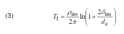
where: ρins – thermal resistivity of insulation, (K.m)/W, δins –thickness of insulation, mm, dc – diameter of conductor, mm.
Thermal resistance T3 of outer covering (sheath) can be calculated as follows:
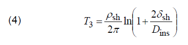
where: ρsh – thermal resistivity of sheath, (K.m)/W, δsh – thickness of sheath, mm, Dins – external diameter of insulation, mm, but thermal resistance T4 of medium surrounding the cable is expressed in the following way:

where: ρsoil – thermal resistivity of soil, (K.m)/W, u – ratio u = 2L/De, L – distance from surface of ground to cable axis, mm; De – external diameter of cable, mm.
Table 1. Correction factors for cables directly buried in the ground or in buried duct for thermal resistivities of the soil different than 2.5 (K.m)/W [15, 17]

Table 2. Standard conditions of soil thermal resistivity for selected countries [18]


Analysis of the above presented considerations regarding power cables current-carrying capacity calculation, enables one to conclude that very important element during cables sizing is assuming thermal resistivity of soil ρsoil and, if necessary, its correction factor. Fig. 2 presents values of a correction factor of the current-carrying capacity for a low-voltage power cable included in Fig. 1 (copper conductor with nominal cross-sectional area 240 mm2, and PVC insulation as well as PVC sheath), as a function of thermal resistivity of the soil. These values have been calculated according to [12, 13], with the assumption that the reference thermal resistivity of the soil is equal to 2.5 (K.m)/W. For a very low thermal resistivity (0.5 (K.m)/W) the correction factor is around 1.8. This factor only slightly depends on the cable depth. Values of the correction factor are also included in standard PN-IEC 60364-5-523 [15] (old standard but still referred in the national regulation [16]), as well as in newer standard PNHD 60364-5-52 [17], which distinguishes cables in ducts from cables directly buried in the ground (Table 1).
In practice, thermal resistivity of the soil can vary in a wide range, what fundamentally influences power cables current-carrying capacity, and many countries recommend their own standard conditions of soil thermal resistivity for power cables sizing purpose (Tab. 2).
Thermal resistivity of the soil strictly depends on its moisture, what is considered in the latter part of this paper.
Soil moisture versus soil thermal resistivity
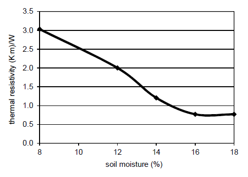
Thermal resistivity of the soil mainly depends on its type (gravel, clay, organic soil, backfill material [19]) and moisture. As it is presented in [20, 21], as well as in Fig. 3, thermal resistivity of sandy-loamy soil significantly rises when its moisture is lower than 14%. Results of the authors’ laboratory test and analysis of the effect of water content in selected types of soil on their thermal resistivity, are presented in Fig. 4, 5 and 6.
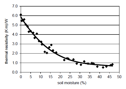
Thermal resistivity of the top layer of the soil with organic particles varies within a very wide range 0.5÷6 (K.m)/W (Fig. 4). Significant rising of the resistivity is observed for the moisture lower than 20% (natural moisture: 19÷26%, [22]).
Laboratory test of the sand (fraction ≤2 mm) indicates that for a 4% and higher sand moisture, its thermal resistivity rather does not exceed 1.0 (K.m)/W (typical value for Poland, according to [18] – see Tab. 2). Rapid rising of sand thermal resistivity occurs for moisture lower than 2%. Such low moisture can occur near the cable, due to its relatively high temperature, during operation with a load close to the current-carrying capacity of the cable. High temperature of the cable causes water migration [23], and for a very long time the real thermal resistivity of the soil can be much higher than assumed in the project stage.

As reference to this conclusion, in the German standard conditions, one can find comment (Tab. 2) that the dry zone near the cable has thermal resistivity equal to 2.5 (K.m)/W.
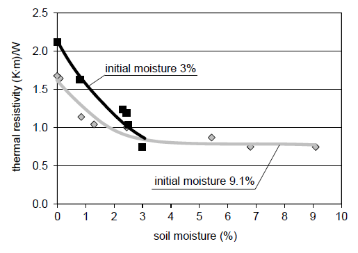
In power cable systems, especially in high-voltage systems, placing cables in a cement-sand surrounding (stabilized backfill) is very common practise. However, according to the laboratory test, thermal resistivity of the cement-sand mixture rapidly rises (worse heat transfer conditions) for its moisture 3% and less (Fig. 6). Very low moisture of this mixture is very likely, due to its close proximity to the hot power cables. Moreover, the thermal resistivity depends on the initial moisture of the cementsand mixture (in the time when the mixture is prepared). Initial moisture of the cement-sand mixture influences its consistency in a steady-state, many days after the cables are installed in the ground. For a higher initial moisture (9.1% vs. 3% – Fig. 6) the resistivity is more favourable (lower values of the resistivity of very dry mixture during cables operation).
Fig. 7 presents temperature distribution around the power cable YKY 1×240 mm2 for various values of soil thermal resistivity, calculated with the use of CYMCAP software [24]. In order to focus only on thermal phenomenon around the cable and eliminate the impact of other factors, e.g. geometric/load asymmetry in four-wire low-voltage systems, all calculations have been made for the simplest arrangement – just only one single-core cable.
Information about current-carrying capacity of this cable is included in caption of Fig. 7. When the thermal resistivity of the soil is lower, the heat transfer along the distance “cable – remote ground” is more intense. In consequence, the current-carrying capacity is higher.
When native soil has relatively high thermal resistivity, e.g. 2.5 (K.m)/W, cables should be surrounded by a stabilized backfill [25] of low thermal resistivity (1.0 (K.m)/W or less) – Fig. 8. It is obvious that a higher area of this backfill improves thermal condition for heat transfer from the cable, and the current-carrying capacity rises. Tab. 3 presents results of the computer calculations in an aggregated form.
However, considering a cable backfill, two factors should be taken into account: backfill properties in various thermal and moisture conditions as well as water migration (drying out of the soil) due to cable heating by load. As it is presented in Tab. 3 and Fig. 9, if water migration occurs due to soil temperature rise (due to heat transfer from the cable), the current-carrying capacity of the cable decreases.
Table 3. Aggregated results of calculations of the cable YKY 1×240 mm2 current-carrying capacity


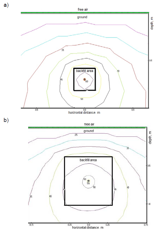

a) 10 cm horizontally and vertically from cable surface, Iz = 633 A,
b) 30 cm horizontally and vertically from cable surface, Iz = 717 A,
c) 50 cm horizontally and vertically from cable surface, Iz = 792 A

Favourable conditions for heat transfer from the cable to soil can be maintained in spite of the soil temperature rise close to the cable. Thermal resistivity of water and the air – both contained in the soil – decrease [20, 26-28] when temperature rises (Fig. 10 and 11).
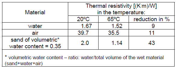
Tab. 4 presents values of thermal resistivity of water, air and sand, when their temperature changes from 20ºC to 65ºC. The latter temperature represents thermal conditions close to a fully loaded cable. It can be observed that thermal resistivity of the hot soil (65ºC) can be over 40% lower than for the conventional ambient temperature (20ºC). Thermal resistivity changing from 2.0 (K.m)/W to 1.14 (K.m)/W then gives a current-carrying capacity rise equal to 25%.
Thus, if migration of water from soil/stabilized backfill is blocked, by using a water barrier, thermal resistivity of the soil/backfill surrounding the cable can be favourable within a wide range of temperatures.
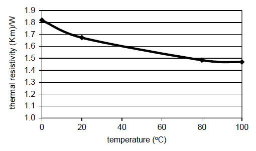
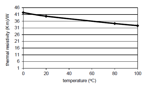
Table 4. Changes of the thermal resistivity of the selected materials, with their temperature [20, 26]
Conclusions
Soil moisture significantly influences current-carrying capacity of power cables, due to its strong impact on thermal resistivity of the soil. In natural environmental conditions, water migration occurs, and a fully loaded cable generates a dry zone near the cable. This negatively influences cable current-carrying capacity, in spite of the use of a stabilized backfill. The current-carrying capacity can be improved by blocking water migration through the soil. Hot soil has lower thermal resistivity than cool soil, at the same content of water.
Further research and calculations will concern current carrying capacity of power cables for their various configurations in three phase-systems, with taking into account thermal properties of native soil as well as stabilized backfill.
REFERENCES
[1] de Leon F., Major factors affecting cable ampacity, IEEE Power Engineering Society General Meeting (PES), 2006
[2] Fan Y. , Li J. , Zhu Y. , Wu Ch., Research on current carrying capacity for XLPE cables installed in pipes, Proceedings of the 9th International Conference on Properties and Applications of Dielectric Materials, July 19-23, (2009), Harbin, China
[3] Hol yk C. , Ander s G. J ., Power cable rating calculations-A historical perspective [history], IEEE Industry Applications Magazine, 21 (2015), No. 4, 6-64
[4] Liang Y., Zhao J., Du Y., Zhang J., An optimal heat line simulation method to calculate the steady-stage
temperature and ampacity of buried cables, Przegląd Elektrotechniczny, (2012), No. 3b, 156-160
[5] Mahmoudi A., Kahourzade S., Lalwani R. K., Computation of cable ampacity by finite element method under voluntary conditions, Australian Journal of Basic and Applied Sciences, 5 (2011), No. 5, 135-146
[6] Teja A. D. , Rajagopala K., Thermal analysis by conduction convection and radiation in a power cable, IOSR Journal of Electrical and Electronics Engineering (IOSR-JEEE), 9 (2014), Iss. 3, 51-56
[7] Zhang W., Li H.-J., Liu Ch., Tan K. Ch., A technique for assessment of thermal condition and current rating of underground power cables installed in duct banks, Asia-Pacific Power and Energy Engineering Conference, (2012), Shanghai
[8] De Mey G., Xynis P., Papagiannopoulos I., Chatziathanasiou V., Exi z i dis L., Wiecek B., Optimal position of buried power cables, Elektronika ir Elektrotechnika, 20 (2014), No. 5, 37-40
[9] Czapp S., Szul tka S., Tomaszewski A., CFD-based evaluation of current-carrying capacity of power cables installed in free air, 18th International Scientific Conference on Electric Power Engineering (EPE), (2017), Kouty nad Desnou, 692-697
[10] Czapp S., Czapp M., Szul tka S., Tomaszewski A. , Ampacity of power cables exposed to solar radiation – recommendations of standards vs. CFD simulations, 17th International Conference Heat Transfer and Renewable Sources of Energy (HTRSE-2018), Międzyzdroje, 02-05.09.2018, E3S Web of Conferences, 70 (2018), 1-5
[11] Chojnac k i A.Ł . , Analysis of reliability of low-voltage cable lines, Przegląd Elektrotechniczny, (2017), No. 4, 14-18
[12] IEC 60287-1-1:2006 Electric cables – Calculation of the current rating – Part 1-1: Current rating equations (100% load factor) and calculation of losses – General
[13] IEC 60287-2-1:2015 Electric cables – Calculation of the current rating – Part 2-1: Thermal resistance – Calculation of the thermal resistance
[14] https://www.tim.pl/kabel-energetyczny-yky-1×240-0-61kvbebnowy-3, Available: 15.11.2018
[15] PN-IEC 60364-5-523:2001 Electrical installations of buildings – Part 5: Selection and erection of electrical equipment – Section 523: Current-carrying capacities in wiring systems
[16] Rozporządzenie Ministra Infrastruktury i Budownictwa z dnia 14 listopada 2017 r. zmieniające rozporządzenie w sprawie warunków technicznych, jakim powinny odpowiadać budynki i ich usytuowanie (Dz.U. z 2017, poz. 2285)
[17] PN-HD 60364-5-52:2011 Low-voltage electrical installations – Part 5-52: Selection and erection of electrical equipment – Wiring systems
[18] IEC 60287-3-1:1999 Electric cables – Calculation of the current rating – Part 3-1: Sections on operating conditions – Reference operating conditions and selection of cable type
[19] IEEE 442-2017 – IEEE Guide for Thermal Resistivity Measurements of Soils and Backfill Materials
[20] Wołkowi ńsk i K., Uziemienia urządzeń elektroenergetycznych, WNT, Warszawa 1967
[21] S kibko Z., Obciążalność prądowa długotrwała kabli ułożonych w ziemi, w świetle norm i przepisów, Wiadomości Elektrotechniczne, 75 (2007), No. 9, 77-86
[22] Yamamoto T. , Soil moisture constants and physical properties of selected soils in Hawaii, U S. FOREST SERVICE RESEARCH PAPER PSW-P2 (1963)
[23] Bates C. , Cain D. , Malmedal K. , Including soil drying time in cable ampacity calculations, IEEE Transactions on Industry Applications, 52 (2016), No. 6, 4646-4651
[24] CYMCAP – software for power cable ampacity rating
[25] Liang-hua Z., Zhi-wei L . , Weiping M., Jian-li Y., Research on increasing cable current-rating by pumping thermal material into pipes, International Conference on Power System Technology, 24-28 Oct., (2010), Hangzhou, China, 1-5
[26] Hi raiwa Y. , Kasubuchi T., Temperature dependence of thermal conductivity of soil over a wide range of temperature (5±75°C), European Journal of Soil Science, 51 (2000), 211-218
[27] Gor i F. , Corasani t i S. , Theoretical prediction of the soil thermal conductivity at moderately high temperatures, Journal of Heat Transfer, 124 (2002), Iss. 6, 1001-1008
[28] Boukelia A., Rosin-Paumier S., Eslami H., Mas rour i F. , Effect of temperature and initial state on
variation of thermal parameters of fine compacted soils, European Journal of Environmental and Civil Engineering, Ed. Lavoisier, (2017)
Authors: dr hab. inż. Stanisław Czapp, prof. PG, Gdańsk University of Technology, Faculty of Electrical and Control Engineering, ul. G. Narutowicza 11/12, 80-233 Gdańsk, Poland, E-mail: stanislaw.czapp@pg.edu.pl
mgr inż. Filip Ratkowski, Research & Development Center, Eltel Networks Energetyka SA, Gutkowo 81D, 11-041 Olsztyn, Poland, E-mail: filip.ratkowski@eltelnetworks.com
Source & Publisher Item Identifier: PRZEGLĄD ELEKTROTECHNICZNY, ISSN 0033-2097, R. 95 NR 6/2019. doi:10.15199/48.2019.06.29
