Published by Mark KLETSEL1, Abdulla KALTAYEV2, Bauyrzhan MASHRAPOV2,
National Research Tomsk Polytechnic University (1), Pavlodar State University (2)
Abstract.The article presents the disadvantages of traditional and some new electric protections of powerful electric motors. It is proposed to eliminate these drawbacks by constructing phase-sensitive protection that does not use current transformers, with a majority circuit and functional diagnostics. The methods of choosing protection settings are given. The algorithm of its functioning, implementation and operation in various modes is considered.The construction for mounting to protect the blocks near the conductors of the motor phases is presented.
Streszczenie. W artykule zaprezentowano mankamenty obecnie stosowanych metod zabezpieczania mocnych silników elektrycznych. Na tej podstawie zaproponowano nową fazoczułą metodę nie korzystająca z przekładników prądowych. Nowa metoda zabezpieczania silników elektrycznych ochraniająca środowisko
Keywords: phase comparison, parameters, operation, majority element, diagnostics, motor protection, magnetically-operated switch
Słowa kluczowe: zabezpieczanie silników elektrycznych, porównanie fazy
Topicality
Powerful electric motors (EM), including with heavy start conditions [1], are usually equipped with overcurrent and differential protection against short circuits [2, 3]. These protections have the following well-known disadvantages: do not reveal coiled-circuit in the stator winding and phase failure (which may cause a fire [4]), sometimes denied due to faults of elements that make up, and, in addition, require current transformers. The devices for early evidence of stator winding failure also require them [5]. Current transformers are metal-intensive (containing tens of kilograms of high-grade steel and copper) and may have unacceptable errors [6,7,8], because of which the differential protection is necessary to complicate significantly. There are proposals [2, 9, 10, 11] to reduce the impact of the errors on the basis of the phase comparison by building defenses. All these protections receive information via a current transformer, except for [11],and do not use special techniques, except for [10], to improve reliability. In this paper we propose a protection [12], which has the advantage of protection on [10] and [11] at the same time.
Protection device
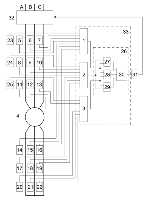
The majoritarian principle of construction “2 of 3” is being used. It is known, this arrangement increases the reliability of operation and failure of dozens of times. The protection consists of failure identification blocks 1, 2, 3, receiving information about the protected motor 4 and the supply cable from its blocks 5-25. Blocks 1, 2, 3 overlap each other as blocks 5, 6, 7; 8, 9, 10; 11, 12, 13; 14, 15, 16; 17, 18, 19; 20, 21, 22; 23, 24, 25.
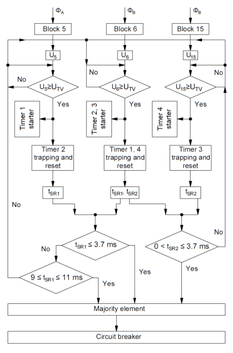
The blocks 5-22 contain two magnetically operated contacts (MC) with the same parameters, the blocks 23-25, one contact. Magnetically operated contacts have been selected when they are used in protective relaying, they have important advantages compared to other magnetically sensitive elements [13, 14, 15]. In this case the blocks 5-13, 23-25 are mounted on the supply side near the electric conductors 4 of phases A, B, C, and the blocks 14-22 from zero leads. The first-contact blocks 5-13, as well as the second-contact blocks 14-22, are triggered in the positive half-wave alternating current, and the second-contact blocks 5-13 and 14-22 first-contact blocks – in the negative. The triggering – this is the first touch of the mobile magnetic contacts of magnetically operated contacts with the fixed plate. It is triggered by a magnetic flux F generated motor phase current in one or the other half-wave of the alternating current. It is provided according to the method described in [16]. Tripping signals are transmitted in the blocks 1, 2, 3 and the connecting cables (as in the conventional traditional protections), and these blocks are fed to majority element 26 consisting of AND the blocks 27- 29 and OR the block 30. The element 26 sends a signal to the execution block 31, if there are signals from any two blocks determining damage. The block 31 gives a command to turn off the switch 32. The blocks 1, 2, 3, and the majority element 26 are a part of the microprocessor 33.The block diagram of the protection device operation algorithm is presented in Figure 2. It shows how to identify Coiled-circuit in phase A (B), phase to phase fault AB (BC) and phase failure C. The rest of the algorithm is easy to imagine on the basis of the analysis of Fig. 1 and 2.
Selection of parameters
It is known that in normal operation of the motor phase angle shift between the currents of 120°, and its interwinding fault is less than 60° (between damaged and undamaged phases) [2] by 180°.
With loss of one phase currents intact phases are shifted by 180°. If there is phase short-circuit in the motor, and in the supply of its cable, faulty phase currents from the power supply and from zero findings are shifted relative to each other by 120°-180° [2].In other modes, the shift between the currents is equal to 0°. Based on the above, assuming that the measurement error can reach 10%, as the operation parameters adopted: by turn-to-turn circuit time between operations of magnetically operated contacts of different phases tSR1≤3.7 ms (corresponds to 66°), in case of interruption phases – 9≤tSR1≤11 ms, for phase short circuits time between operations of magnetically operated contacts of one phase (from the input terminals, and zero) – 0≤tSR1≤3.7ms. In the latter case, it is taken 3.7 ms instead 6.6-10 ms (120°-180°), because the contacts magnetically controlling interphase circuit triggered in different half-wave alternating current in the normal mode tSR=10 ms. The level of current bus systems in motor phases at which controlled the angle between the phase currents (in fact it is a current of protection operation) must be at least by turn-to-turn circuit current IIA idling in “K” times, where K=(1.5-2) It corresponds to the coefficient of sensitivity of current protection. Otherwise, magnetically operated contacts do not work, because at turn-to-turn circuit during idling (in a load operation), the value in the current phase changes insignificantly [2]. Since the currents of idling motor make up (0.1-0.5) In, where In – rated motor current, the currents in such conventional magnetically operated contacts, produced in Russia, can be insensitive. The minimum induction in the magnetic field required for the operation of magnetic contacts, is determined by the following formula [17]:

where μ0 – permeability of air; γ – the angle between the vector of magnetic induction created by a conductor, and the longitudinal axis of the MC; ISR – the minimum value of the current in the conductor, in which the contact is triggered magnetically; FSR – magnetomotive force (m.m.s.) solenoid actuation contact; Lk – the length of the solenoid, in which magnetomotive force is measured; h – the distance between the center of gravity of the magnetic contacts and a conductor.
For example, the minimum m.m.s. FSR corresponding to the position of contact with the magnetically γ=0° and h=0.02 m, engine capacity of 2 MW with load current In=230 A current and idle IIA=46 A, is equal to 4.8 A. This value m.d.s. is not sufficient to trigger the very magnetically sensitive contact, manufactured in Russia, – ICA-14103, as its m.d.s. It is within 8-35 A. Sensitivity can be increased by about 8-9 times with a DC bias [13], or use a Japanese mercurymagnetically operated contacts, which is much more sensitive and more durable but more expensive.
Operation in the different modes in the absence of faults in it
When turn-to-turn circuit and loss of one phase of the motor 4 in the positive half-wave of the AC unit 1 receives signals from the first block of magnetically contacts 5-7.
For example, when turn-to-turn circuit in the phase A, or phase failure C, in blocks 5 and 6 are activated first magnetically operated contacts, and at the output of the voltage appearing U5 and U6 (Fig. 2), which are fed into the unit 1, which compares with a threshold UTV value. If the solenoid contact block 5(6) is activated earlier, U5≥UTV (U6≥UTV), and starts a TIMER 1(2). It counts the time until the solenoid has not yet triggered the contact block 6(5) as U6≥UTV (U5≥UTV), then TIMER 1(2) stops. Recorded time between operations of magnetically operated contact will be stored and compared with the adopted setpoint to detect interturn short circuits. If tSR1≤3.7 ms, the signal is in a majority element 26. If tSR1≥3.7 ms, the phase failure condition is tested, wherein 9≤tSR1≤11 ms. When the latter signal is also applied to an element 26 which runs the block 31, the switch 32 is switched off. Behaves similarly to the negative half-wave device AC when triggered magnetically contacts the second block 5 and 6. Similarly, as the blocks 5 and 6, the blocks 8 and 9 run, 11 and 12, and then the blocks 2 and 3, the signals from the last served in block 26.
If there is interphase short circuit inside the motor 4 or the cable connecting it to a switch 32, for example between phases A and B, the first magnetically operated contacts blocks 5(6) and the second magnetically operated contacts blocks 14(15) are activated in one half-wave alternating current, and the second magnetically operated contacts blocks 5(6) and the first magnetically operated contacts blocks 14(15) – in the other, and also, as described in the preceding paragraph, checked the condition of 0<tsr2≤3.7 ms.
To protect the motor 4 from the three-phase short circuit at the time of its inclusion blocks 23-25 are provided with magnetically operated contacts, detuned from the start-up currents.
Construction for mounting of blocks with magnetically operated contacts
The installation of units with reed contacts 5-25 near the motor can be carried out using a special attachment construction, for example, [18] and shown in Figure 3.
The latter allows you to mount the blocks on each phase of the motor. The construction consists of a housing 1 with a cover, made in the form of a parallelepiped. The housing is secured to the current-carrying conductor 2 by means of guide units 3 and 4. The pins inside the housing obliquely positioned strip 5 with fixed parallel units with reed contacts 6. All units with reed contacts by means of connecting wires 7 are connected to the terminal block 8, to which connect the microprocessor and the source of the operational DC.
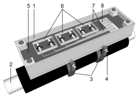
Fig.3. Construction for mounting blocks with magnetically operated contacts near the motor phases: 1 – a body with cover (cover made of transparent material); 2 – busbar; 3 – rail links; 4 – pins; 5 – lath; 6 – blocks with magnetically operated contacts; 7 – connecting cables; 8 – terminal block
Failure diagnosing
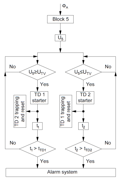
The structural diagram of failure diagnosing algorithm is shown in figure 4.
By the of magnetically-operated switch fritting in the blocks 5-25, for instance, in block 5, a voltage is applied (Fig. 4) on the body of the first time delay (TD1) which controls the time t1 malfunction. If t1≥tTD1 (tTD1 – the time set in the TD1), then a fault signal will be emitted.
If there is no fault, then t1<0.01 s, because the magnetically-operated switch is activated and there is no contact within one halfwave of the alternating current by providing a polarity response [16]. Therefore, taking tTD1=0.02 s we can detect magnetically-operated switch fritting. If the wires are broken or if the unit is destroyed due to lack of voltage, the time delay starts second body (TD2), which controls the time t2 failure in the absence of the signal, and if t2≥tTD2 (tTD2 – time set on TD2), the signal is fault. When these faults occur in any circuit device of the considered motor or damage the cable, the signals from the undamaged blocks 8-13 and 17-25 come into blocks 2 and 3, which, in turn, provide signals to the element 26 and protection fires.
Conclusion
1. The considered method for determining the angle between the motor phase currents can detect phase to phase and Coiled-circuit.
2. The received construction gives an opportunity to save copper and steel to protect and preserve the working capacity at fault in any one of its units.
3. The proposed construction allows to strengthen the protection units to the cores of entrance motor cable.
REFERENCES
[1] Jakub Bernatt, Silniki wysokiego napięcia dla trudnych warunków rozruchowych (projektowanie i wykonawstwo), Przeglad Elektrotechniczny, 2010, No. 8, 294-297
[2] Korogodskii V.I., Kuzhekov S.L., Paperno L.B., Relay protection of electric voltages above 1 kV, M.: Elektroatomizdat, 1987, 248
[3] Andreev V.A., Relay protection and automation of power systems: a textbook for high schools – 4 th ed. Revised. and additional, M.: Wysshaya. shkola, 2006. 639
[4] Andrzej Szczurek, Fires cause by electric reasons, Przeglad Elektrotechniczny, 2010, No. 9, 351
[5] Czesław Kowalski, Marcin Wolkiewicz, Paweł Ewert, Analysis of stator faults of the induction motor fed from net and static converter, Przeglad Elektrotechniczny, 2008, No. 12, 64-67
[6] Kuzhekov S.L., Nudelman G.S. About ways to reduce the errors of current transformers in transient influence on the work of relay protection of electric power systems, the International Scientific and Technical Conference of CIGRE: Modern directions of development of systems of relay protection and
automation of power systems, Moscow 7-10 September 2009, 99-104
[7] Xuesong Zhou, Zhihao Zhou, Youjie Ma, Dongfang Wu. Analysis of Excitation Current in DC-Biased Transformer by Wavelet Transform, Przeglad Elektrotechniczny, 2012, No. 05b, 108-112
[8] Waldemar Rebizant, Krzysztof Solak, The impact of current transformers saturation on operation of transmission lines protection relays, Przeglad Elektrotechniczny, 2010, No. 11a, 303-307
[9] A. Bogdan, Voronich I.A., Kletsel M.J., Nelyubin V.P., Differential-phase motor protection, Electric station, 1979, No. 2, 63-65
[10] Kletsel M.J., Musin V.V., Simonov S.N., Polyakov V.E. Protection of motors with phase-sensitive majority circuit and functional diagnosis, Electricity, 1990, No. 10, 27-32
[11] The innovative patent of the Republic of Kazakhstan 22073. The device to protect the motor from all kinds of stator winding circuits / Kletsel M. J. Publ. 18.12.2009. Bull. , No. 12.
[12] Patent of the Russian Federation No. 2570641. The device to protect the motor and its supply cable against short-circuit and phase failure / Kaltayev A.G., Kletsel M.J., Mashrapov B.E., Mashrapova G.N .Publ. 2014 Bull. , No. 34.
[13] Kletsel M.J., The principles of differential protection to the electrical reed switches, Electrical Engineering, 1991, No. 10, 47-50
[14] Kletsel M.J., Maishev P.N. Features of the construction of the differential-phase protections of transformers, Electrical Engineering, 2007, No. 12, 2-7
[15] Zhantlesova A.B., Kletsel M.J., Maishev P.N ., Neftis A.V. Identification of steady short-circuit current, Electrical Engineering, 2014, No. 4, 28-34
[16] Mark Kletsel, Nariman Kabdualiyev, Bauyrzhan Mashrapov, Alexander Neftissov Protection of busbar based on reed switches, Przeglad Elektrotechniczny, 2014, No. 1, 88-89
[17] Kletsel M.J., Musin V.V. On the construction of reed switches on the protection of high-voltage installations without current transformers, Electrical Engineering, 1987, No. 4, 11-13
[18] Patent of the USSR , No. 1767568. Measuring body for overcurrent / Dahno V.A., Kletsel M.J., Musin V.V., Metel’skii A.N., Alishev J.R. Publ. 07.10.1992. Bull. No. 37.
Authors: prof. doctor of technical sciences mr. Mark Kletsel, National Research Tomsk Polytechnic University, Tomsk, Russian Federation; mr. Abdulla Kaltayev, Pavlodar State University, Electroenergetics Faculty, Pavlodar, Lomov str., 64, Republic of Kazakhstan, E-mail: abdulla911@mail.ru; mr. Bauyrzhan Mashrapov, Pavlodar State University, Electroenergetics Faculty, Pavlodar, Lomov str., 64, Republic of Kazakhstan, E-mail: bokamashrapov@mail.ru.
Source & Publisher Item Identifier: PRZEGLĄD ELEKTROTECHNICZNY, ISSN 0033-2097, R. 93 NR 5/2017. doi:10.15199/48.2017.05.09
