Published by S. Abdul Rahman1, Shumye Birhan Mule2, Estifanos Dagnew Mitiku3, Gebrie Teshome Aduye4, C. Gopinath5, Department of Electrical & Computer Engineering, Institute of Technology, University of Gondar, Ethiopia (1, 2, 3, 4) Department of Electrical & Electronics Engineering, Sri Venkateswara College of Engineering, Chennai, India (5)
Abstract: The aim of this paper is to explain the control algorithm very clearly and precisely to achieve maximum voltage sag compensation of 52% and infinite quantity of voltage swell using direct converter based DVR. The proposed DVR topology has a single phase matrix converter (SPMC), series transformer and LC filter. If the duty cycle of the PWM is digitally computed by measuring the available voltage at the supply and the percentage of voltage sag, it is possible to mitigate 52% of voltage sag and infinite quantity of voltage swell with the THD less than 1%. Matlab Simulation results are presented for validating the analysis.
Streszczenie: Celem artykułu jest precyzyjne wyjaśnienie algorytmu sterowania w celu uzyskania maksymalnej kompensacji zapadu napięcia wynoszącej 52% i wzrostu napięcia przy użyciu rejestratora DVR z bezpośrednim przetwornikiem. Proponowana topologia DVR ma jednofazowy konwerter macierzy (SPMC), transformator szeregowy i filtr LC. Jeżeli cykl pracy PWM jest obliczany cyfrowo poprzez pomiar dostępnego napięcia na zasilaniu i procentu zapadu napięcia, możliwe jest złagodzenie 52% zapadu napięcia i wielkości wzrostu napięcia przy THD mniejszym niż 1%. Wyniki Matlab Simulation są prezentowane w celu walidacji analizy. (Kompensacja zapadów i wzrostu napięcie przy wykorzystaniu jednofazowego przekształtnika macierzowego z czterema przełącznikami)
Keywords: Voltage Sag, Voltage Swell, Single Phase Matrix Converter, DVR, Series Transformer, Digital PWM technique.
Słowa kluczowe: zapad napięcia, wzrost napięcia, jednofazowy przetwornik matrycowy, DVR, transformator szeregowy, ctechnika PWM
Introduction
Though we have many power quality issues like voltage sag, voltage swell, flicker, harmonics, etc., voltage sag is considered to be the severe issue as it affects the operation of sensitive loads like computer, micro controller, Digital Signal Processor, FPGA. As most of the industries are automated, the entire operation of the industries depends upon the operating condition of these embedded systems and sensitive loads. When sag or swell occurs in the industrial areas, these sensitive loads are getting affected, leading to immoral operation of the entire industry [1, 2]. For the compensation of voltage sag, Dynamic Voltage Restorer (DVR) considered to be an effective device when compared to other devices like UPS, STATCOM [3-5].
DVR is a series compensator, which is used to add the compensating voltage in series with the line voltage in order to mitigate voltage sag, swell, harmonics, flicker, etc. A conventional DVR has an energy storage device ( which may be a battery bank or capacitor or super capacitor), an inverter to convert the DC power in the energy storage device to AC power and a series transformer to inject the AC power generated by the inverter, in series with the line voltage. When a power quality issue occurs on the supply side, the inverter synthesis the required compensating voltage by taking power from the energy storage devices and injects the compensating voltage in series with the line voltage using the series transformer [6-8]. The compensating range and duration of mitigation of voltage sag and swell, of this topology is based on the rating of the energy storage devices. This conventional DVR has disadvantages like heavy weight, volume, uneconomical, more maintenance due to the energy storage devices [9- 11]. In order to overcome, these disadvantages, recently DVRs based on direct converters are proposed. In this topology, the energy storage devices are not used. Instead the power is taken from the supply side itself to mitigate the power quality issues. As the power is taken form the supply side to mitigate the power quality issues, this topology uses direct converters to synthesis the compensating voltage. A series transformer is used to inject the output voltage of the direct converter, in series with the line voltage. So when a voltage sag or swell occurs, the direct converter will synthesis the required compensating voltage by taking power from the supply side and the compensating voltage is added in series with the line voltage using the series transformer . As this topology didn’t used energy storage devices, it is not having disadvantages like topology based on energy storage devices. The compensating range and the mitigating duration of this topology is based upon the direct converter topology, modulating techniques and the availability of input voltage for the direct converter [12-16].
In the literature, very few publications are available for the DVRs based on the direct converters as it is recent technique. Out of those publications, the topology presented in [17] can mitigate 50% of voltage sag and 100% of swell by taking power from the same phase. The topologies presented in [18, 19] can mitigate 33% of voltage sag and 100% of voltage swell by taking power form the different phases. Though the topologies in [20-22] are based on direct converters, they can mitigate voltage sag, swell and also single outage. Based on the modulating techniques, the voltage sag and swell compensating range could be improved [23, 24]. In this paper, the DVR is realized using a Single Phase Matrix Converter (SPMC), which is a direct converter. The single phase matrix converter is realized using only four controlled switches but so far the single matrix converter is been realized using 8 controlled switches. As it is realized with 4 controlled switches, the generation of PWM pulses are very easy while compared to generation of switching pulses for 8 controlled switches. With the presence of 8 switches, the commutation problem occurs. But with 4 controlled switches, no commutation problems occurs as there is one bidirectional switch for each phase. In this paper, the achievement of 52% voltage sag compensation is clearly explained in a detail manner.
It is observed from the analysis that to mitigate voltage sag and swell by taking power from the same phase, using a DVR based on direct converter, by ordinary PWM technique, it is possible to achieve only 22% of sag and swell compensation. If the duty cycle of the PWM is digitally computed by measuring the available voltage at the supply side and the percentage of voltage sag, it is possible to mitigate 52% of voltage sag and infinite quantity of voltage swell with the THD less than 1%.
Principle of operation
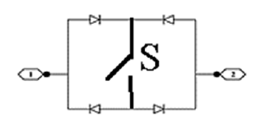
The topology of DVR is been shown in the figure 1. It has a single phase matrix converter, a LC filters at the input side of the single phase matrix converter and another LC filter at the output side of the single phase matrix converter, and a series transformer. The LC filters are to minimize the harmonics due to switching both at the input side and also at the output side. The single phase matrix converter has four bidirectional switches S1, S2, S3 and S4 as shown in the figure 1. Each bidirectional switch has only one controlled switch. The topology of the bidirectional switch is shown in the figure 2 where the switch S could be IGBT, MOSFET or BJT. When the supply voltage is at rated value, the switches S3 and S4 are closed and the other two switches S1 and S2 are open. In this condition, the secondary of the series transformer is short circuited which results in zero voltage injection and the load voltage is maintained at its rated value. When the voltage sag occurs, the DVR will synthesis the compensating voltage by taking power from the same phase and operating the switches S1, S4 and S3 alternatively. The compensating voltage is added in phase with the supply voltage through the series transformer. The turns ratio of the series transformer is 1:1.
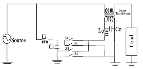
When swell occurs, the DVR will operate the switches S3, S4 and S2 alternatively such that the compensating voltage is added out of phase with the supply voltage through the series transformer.
Control algorithm
From the figure.1 we could observe that the load voltage Vload is equal to the summation of source voltage Vsupply and the compensating voltage Vcompensating synthesized by the SPMC.
(1) Vsupply + Vcompensating = Vload
We could write compensating voltage as the difference between the rated supply voltage and the voltage available at the supply side.
(2) Vcompensating = Vrated – Vsupply
As the SPMC, takes power from the same phase to compensate both sag and swell, we could write compensating voltage generated by the SPMC as
(3) Vcompensating = Vsupply × Ton
The on time of the PWM should be according to the existing value of sag or swell occurrence in the supply side. So
(4) Ton = Vcompensating ÷ Vsupply
The supply side voltage is measured and the peak value of the supply voltage is calculated using single phase dq theory [25]. The difference between the rated voltage and the supply side voltage gives the value of the compensating voltage as given in equation (2). The ratio of the compensating voltage and the supply voltage gives the percentage Ton period of the switching pulse, as per the equations (3) and (4). It could be understood from the figure 1 that in order to compensate sag, the SPMC should inject a voltage in phase with the supply voltage. To do so, the switches S1and S3 should be alternatively modulated and the switch S4 should be closed and S3 should be open. The figure 3 shows the logic of generating the PWM for all the four switches.

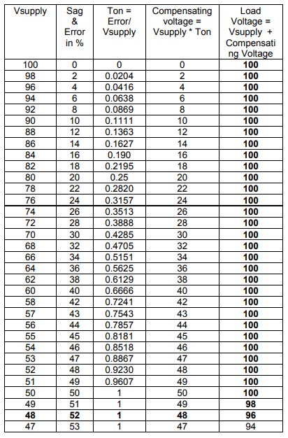
A micro controller compares the peak value of the supply voltage with the reference voltage value. If the peak value of the supply voltage is less than the peak value of the reference voltage immediately the S4 is closed and S3 is opened. The same micro controller is used to generate the PWM pulses for switch S1 by dividing the magnitude of the compensating voltage (error signal) by the peak value of the supply voltage. The complimentary PWM of switch S1 is the PWM for switch S3. In this logic the PWM for all the four switches are generated. Moreover, Table 1 shows the sag compensating range of 22% by the SPMC when ordinary PWM technique is used. By using digital PWM technique it is possible to compensate a voltage sag of 52% as shown in the table 2. It could be observed from the table 2 that the compensated load voltage is maintained within the IEEE standard value. It is very well known that for both the voltage and the frequency, variation allowed as per the IEEE standard is ±5%.
In the same approach, voltage swell is mitigated. It could be understood from the figure 1 that in order to compensate voltage swell, the SPMC should inject a voltage out of phase with the supply voltage. To do so, the switches S2and S4 should be alternatively modulated and the switch S3 should be closed and S1 should be open. The figure 4 shows the logic of generating the PWM for all the four switches. Moreover, Table 3 shows the swell compensating range of 22% by the SPMC when ordinary PWM technique is used. By using digital PWM technique it is possible to compensate a swell of any magnitude as shown in the table 4.
Table 1. Possible Voltage Sag Compensation with ordinary PWM technique

Table 2. Voltage Sag Compensation by Digital PWM technique

It could be observed from the table 4 that the compensated load voltage is maintained within the IEEE standard value of ±5% deviation throughout the voltage swell compensation.
Table 3. Possible Voltage Swell Compensation with ordinary PWM technique

Table 4. Voltage Swell Compensation by Digital PWM technique

Simulation results
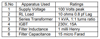
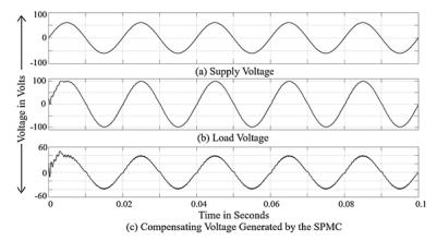
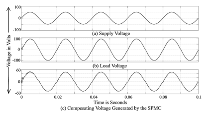
For easy understanding, the rated value of supply voltage is set with the amplitude of 100V, 50Hz. The DVR operates with the filter inductance of 1mH and filter capacitance of 15uF at the carrier frequency of 4 KHz. The resonance frequency Fr, of the LC filter should be greater than the system frequency 50 Hz and less than the PWM switching frequency 4KHz. In order to minimize the size of the inductor and the capacitor, a resonance frequency Fr of 1300 Hz has been chosen. The value of L & C are obtained from the formula Fr = 1/ (2π√LC). The simulation model parameters are given in table 4.
Table 5. Parameters of simulation model
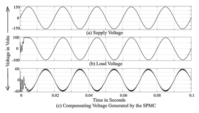
The following figures figure.4, figure.5, figure.6 and figure7shows the ability of the control algorithm to mitigate sag from 0 to 52%

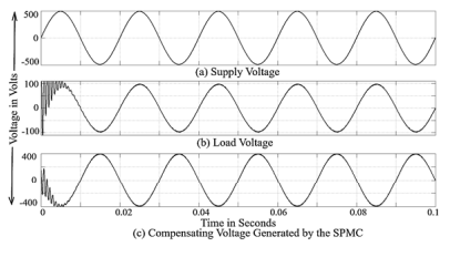
Voltage swell compensation from 0 to 800% is shown in the figures figure.8, figure.9, figure.10 and figure11.


Conclusion
In this paper, the DVR is realized using a Single Phase Matrix Converter (SPMC), which is a direct converter. The single phase matrix converter is realized using only four controlled switches but so far the single matrix converter is been realized using 8 controlled switches. As it is realized with 4 controlled switches, the generation of PWM pulses are very easy while compared to generation of switching pulses for 8 controlled switches. With the presence of 8 switches, the commutation problem occurs. But with 4 controlled switches, no commutation problems occurs as there is only one bidirectional switch for each phase. It has been demonstrated in this paper that it is possible to achieve 52% of sag compensation and unlimited amount of voltage swell compensation by digital PWM technique using a DVR based on the single phase matrix converter with THD less than 1%.
REFERENCES
[1] Amr Abou-Ghazala , Ashraf Megahed , Ahmed Hassan : Mitigation of Steel Making Plants’ Electrical Power Quality Problems Using SVC – A Case Study, PRZEGLĄD ELEKTROTECHNICZNY, 7, 2016.
[2] Paweł Kostyła , Jacek Rezmer , Adam Gubański , Jarosław Szymańda : Synthetic indices for power quality assessment for distributed generation, PRZEGLĄD ELEKTROTECHNICZNY, 10/2017.
[3] Zbigniew Hanzelka , Andrzej Firlit , Bogusław Świątek , Krzysztof Piątek , Mateusz Dutka , Tomasz Siostrzonek : Analysis of selected power quality indicators at non-measured distribution network points based on measurements at other points, PRZEGLĄD ELEKTROTECHNICZNY, 05/2020.
[4] Suma Jothibasu and Mahesh K. Mishra, “A Control Scheme for Storage less DVR Based on Characterization of Voltage Sags,” IEEE Transactions on Power Delivery, Vol. 29, no. 5, 2014.
[5] Jiangfeng Wang, Yan Xing, Hongfei Wu and Tianyu Yang,” A Novel Dual-DC-Port Dynamic Voltage Restorer with ReducedRating Integrated DC–DC Converter for Wide-Range Voltage Sag Compensation,” IEEE Transactions on Power Electronics, Vol. 34, no. 8, 2019.
[6] Grzegorz Benysek , Ryszard Strzelecki , Daniel Wojciechowski, Dynamic voltage restorer arrangements. Application and properties. PRZEGLĄD ELEKTROTECHNICZNY, 02/2008.
[7] Azah Mohamed , Mahammad Hannan : Study of Basic Properties of an Enhanced Controller for DVR Compensation Capabilities, PRZEGLĄD ELEKTROTECHNICZNY, 04a/2012.
[8] Jiangfeng Wang, Yan Xing, Hongfei Wu and Tianyu Yang, “A
Novel Dual-DC-Port Dynamic Voltage Restorer with ReducedRating Integrated DC-DC Converter for Wide-Range Voltage Sag Compensation,” IEEE Transactions on Power Electronics, vol. 34, no. 8, 2019.
[9] Abdul Rahman, “Realization of Single Phase Matrix Converter Using 4 Controlled Switches,” International Journal of Engineering, Applied and Management Sciences Paradigms, vol. 54, no. 7, 2019.
[10] R. Omar and N. A. Rahim, “Voltage unbalanced compensation using dynamic voltage restorer based on supercapacitor,” International Journal of Electrical Power & Energy Systems, vol. 43, no. 1, December 2012.
[11] Bartosz Pawlicki, Loads forming in power distribution networks by voltage regulation with DVR, PRZEGLĄD ELEKTROTECHNICZNY, 09/2013.
[12] Suma Jothibasu and Mahesh K. Mishra, “A Control Scheme for Storage less DVR Based on Characterization of Voltage Sags,” IEEE Transactions on Power Delivery, vol. 29, no. 5, 2014.
[13] PA Janakiraman, S Abdul Rahman, “Linear pulse width modulation under fluctuating power supply,” IEEE Transactions on Industrial Electronics, vol. 61, no 4, pp. 1769-1773, 2013.
[14] Prasai, and D.M. Divan, “Zero-energy sag correctorsOptimizing dynamic voltage restorers for industrial application,” IEEE Trans. Ind. Appl., vol. 44, no. 6, pp. 1777-1784, 2008.
[15] Wang, and G. Venkataramanan, “Dynamic voltage restorer utilizing a matrix converter and flywheel energy storage,” IEEE Trans. Ind. Appl.,vol. 45, no. 1, pp. 222-231, 2009.
[16] E. Babaei, M.F. Kangarlu, and M. Sabahi, “Mitigation of Voltage Disturbances Using Dynamic Voltage Restorer Based on Direct Converters,” IEEE Transactions on Power Delivery, vol. 25, no. 4, pp. 2676-2683, 2010.
[17] Abdul Rahman Syed Abuthahir, Somasundaram Periasamy, Janakiraman Panapakkam Arumugam, “Mitigation of Voltage Sag and Swell Using Direct Converters with Minimum Switch Count,” Journal of Power Electronics, vol. 14, no. 6, pp. 1314-1321, 2014.
[18] S. Abdul Rahman, P.A. Janakiraman and P. Somasundaram, “Voltage sag and swell mitigation based on modulated Carrier PWM,” International Journal of Electrical Power and Energy Systems, Elsevier, vol. 66, pp. 78-85, 2015.
[19] S. Abdul Rahman and P. Somasundaram, “Voltage sag and swell compensation using AC/AC converters,” Australian Journal of Electrical & Electronics Engineering, vol. 11, no. 2, pp.186-194, 2014.
[20] S. Abdul rahman, “Direct Converter Based DVR to Mitigate Single Phase Outage,” International Journal of Recent Technology and Engineering (IJRTE), vol. 8, no.3, pp.85-88, September, 2019.
[21] Abdul Rahman, “Mitigation of Voltage Sag, Swell and Outage without Converter,” International Journal of Latest Transactions in Engineering and Science (IJLTES), vol. 8, no. 1, 2019.
[22] Abdul Rahman, “Mitigation of Single Phase Voltage Sag, Swell and Outage Using Voltage Controlled Voltage Source,” Global scientific Journal, vol. 7, no. 10, 2019.
[23] S. Abdul Rahman, Gebrie Teshome, “Maximum voltage sag compensation using direct converter by modulating the carrier signal,” International Journal of Electrical and Computer Engineering (IJECE), vol. 10, no. 4, 2020.
[24] S. Abdul Rahman, Estifanos Dagnew, “Voltage sag compensation using direct converter based DVR by modulating the error signal,” Indonesian Journal of Electrical Engineering and Computer Science, Vol 19, No 2: August 2020.
[25] S. Abdul rahman, and P. Somasundaram, “Mitigation of Voltage Sag and Swell Using Dynamic Voltage Restorer without Energy Storage Devices,” International Review of Electrical Engineering, vol. 7, vo.4, pp. 4948-4953, 2012.
Authors: Associate Professor, Dr. Abdul Rahman, Department of Electrical & Computer Engineering, Institute of Technology, University of Gondar, Gondar, Ethiopia, Email: msajce.abdulrahman@gmail.com; Lecturer, Mr. Shumye Birhan Mule, Department of Electrical & Computer Engineering, Institute of Technology, University of Gondar, Gondar, Ethiopia, Email: shumyeb9@gmail.com; Lecturer, Mr. Estifanos Dagnew Mitiku, Department of Electrical & Computer Engineering, Institute of Technology, University of Gondar, Gondar, Ethiopia, Email: est7eced@gmail.com; Lecturer, Mr. Gebrie Teshome Aduye, Department of Electrical & Computer Engineering, Institute of Technology, University of Gondar, Gondar, Ethiopia, Email: gebrie.415@gmail.com; Associate Professor, Dr. C. Gopinath, Department of Electrical & Electronics Engineering, Sri Venkateswara College of Engineering, Chennai, India, Email: cgopinath@svce.ac.in;
Source & Publisher Item Identifier: PRZEGLĄD ELEKTROTECHNICZNY, ISSN 0033-2097, R. 97 NR 4/2021. doi:10.15199/48.2021.04.24
