Published by Artur NEMŚ, Magdalena NEMŚ, Adam RUZIEWIC, Wroclaw University of Science and Technology, Poland
Abstract. The article describes the method and criteria of selecting wind turbines used to heat domestic hot water (DHW). The authors describe a method of choosing turbines based on power characteristics, climatic conditions and heating demands of a building. Power characteristics are described together with power utilisation factors for turbines with a horizontal and vertical axis. Special attention has been drawn to power utilisation factor of the turbine, which depends on climatic conditions and is a better parameter of turbine selection than power characteristics.
Streszczenie. W artykule opisano sposób i kryteria doboru turbin wiatrowych służących do podgrzewania ciepłej wody użytkowej (CWU). Przedstawiono metodę doboru turbin do systemu, uwzględniającą charakterystykę mocy, warunki klimatyczne oraz potrzeby grzewcze budynku. Pokazano charakterystyki mocy i współczynniki jej wykorzystania dla turbin z poziomą i pionową osią obrotu. Zwrócono uwagę na wskaźnik wykorzystania mocy turbiny, który jest zależny od warunków klimatycznych i jest lepszym parametrem w doborze turbin niż charakterystyka mocy. (Kryteria doboru i analiza pracy turbin wiatrowych do podgrzewu CWU).
Keywords: water heating system, small wind turbines, annual analysis.
Słowa kluczowe: system podgrzewu wody, małe turbiny wiatrowe, roczna analiza.
Introduction
Home wind power plants consisting of a wind turbine, an inverter and an accumulator, often accompanied by photovoltaic modules [1], are usually installed to reduce electricity bills, although, basically, they have been created to provide energy security [2]. They are usually used to power energy consuming (electrical) home equipment. They are also useful in summer cottages, with relatively small demand for electricity. An unquestionable advantage of home wind power plants is their easy mounting, resulting from the simple construction of the whole system. Another thing is simplified administrative procedure in case of mounting turbines on a construction that is not permanently fixed to the ground. It is becoming more common for wind turbines to cover the demand for domestic hot water. Such a solution is beneficial due to a smaller number of installation elements, which results in less energy losses. Furthermore, its advantage is the possibility to use low quality energy obtained in conditions of significant wind speed variabilities [3]. When considering such an installation, one must first do the research related to wind conditions in the given area, so that the investment is profitable. The ways of using electricity generated by wind turbines are shown in Figure 1.

Installation used to cover the requirements of individual recipients are called small wind turbines – SWT. The advantages of such turbines include [5,6]:
• the ability to be used in different geographical regions, as they start to work at the wind speed of 2 m/s.
• resistance to constant strong wind and abrupt gusts.
• relatively simple installation,
• acceptable investment costs,
• negligibly small effect on the environment,
• the ability to be integrated in the surrounding
Schematic drawing of such an installation is shown in Figure 2.

Domestic hot water demand
In order to choose appropriate power of the installation, one must first of all determine the energy requirements for preparing domestic hot water. In Poland there are a few methods of determining the demand for DHW. One of them, described in [7] defines the amount of day demand with equation
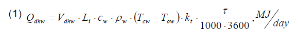
where: Qdhw – heat demand, Vdhw – unit usage of domestic hot water, Li – number of reference units, cw – specific heat of water, ρw – water density, Tcw – temperature of hot water in the faucet, Tow – temperature of cold water, kt – corrective multiplier for hot domestic water temperature, τ – time.
The same relation can be found in [8]. According to guidelines included, it is assumed that the demand for hot water per one inhabitant of a house is 35 dm3/day. It is worth applying this method for new constructions, when water consumption is not known. Another methodology, described with equation (2) was presented in [9]. It does not take account of the influence of water temperature and irregular usage of water, only the value of total water demand.
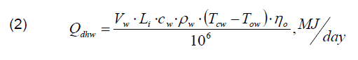
where: ηo – proportion of hot water in total water demand per person.
This method allows to determine the amount of energy required to prepare DHW on the basis of water bills, assuming that 60÷70% of water used is heated. However, it does not take account of DHW tank losses. These losses can be determined if we know the tank’s parameters. Figure 3. shows the relationship between heat losses from DHW tank’s surface and its size.
The size of accumulation tank should be chosen on the grounds of users’ needs. Assuming that DHW tank capacity is equal to the amount of hot water used per day, we can eliminate the problem of periodicity and intensity of water heating with the wind turbine system that could affect the discrepancy in heat demand and supply during a day.

If the installation using wind turbine to heat DHW is not additionally connected to electric power system, then it is an important aspect to use possible surplus of heat in a good way. According to the presented methods of determining heat demand [7,8,9] it is assumed that the temperature of heated water is around 55 ⁰C. It allows to accumulate heat surplus by increasing temperature of water in DHW tank. Another solution is choosing a bigger tank. However, each of these methods involves increased stream of heat losses from such an accumulator.
Losses in electrical cables
When designing electrical installation, it is necessary to choose proper solutions ensuring appropriate protection against thermal and electrical influence of the installation on the surrounding and the other way around. Selection of electrical cables or conduits consists in determining minimum cross section, taking account of long-lasting current capacity and overload, voltage drop, conditions causing short circuit, and with fire protection in mind. One of the most important issues is choosing proper insulation with relation to nominal voltage.
Electrical cables used in photovoltaic installations have to meet certain requirements [11], including:
• cables must be flexible enough in order to cause no inconvenience during mounting,
resistant to UV radiation,
• it is required that the material, that cables are made of, is resistant to different kinds of chemical factors,
• working temperature of PV installation cables should be above 100 degrees Celsius and the core during short circuit should endure the temperature of over 200 degrees for a few seconds,
• cables should be fitted to periodical work below 0⁰C, as it is assumed they will work throughout the year,
• they should be durable enough, in order to guarantee work during the installation’s failure-free period.
When considering the profits and losses of wind turbine installation used for heating DHW, one must take account of energy losses related to transferring electrical power between wind turbine and heater placed in accumulative tank. In order to determine energy lost on cables, we have to take equation (3) and determine electric resistance for one meter of DC cable of a given diameter.
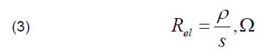
where: Rel – cable resistance, ρ – cable resistivity, s – cable cross-section.
Generated heating, called Joule heating is described with equation (4).

where: q̇l – stream of electrical cable heat loss, I – current.
Total value of the stream of heat lost depends on cable length and is described wit equation (5).

where: Q̇l – stream of heat lost in electrical cables, L – electrical cable length.
Due to the difficulty to determine momentary current values for calculations, a maximum value resulting from the power of wind turbine can be assumed. It will allow to determine the amount of heat lost during a day (τ=86400 sec) from relation (6).
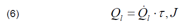
where: Ql – heat lost in electrical cables.
Furthermore, it will result in determining maximum losses on cables, making the selected turbine power insufficient. It is, however, possible to obtain bigger amount of heat for water heating than it has been calculated, The authors believe that such an assumption will not cause any significant changes in energy balance, as even such oversized losses on cables will constitute about 10% of losses from accumulative tank.
Selection criteria of wind turbines
When selecting a system for heating DHW, like a wind turbine, one has to consider the aforementioned unevenness in supplying heat and changeable intensity [12]. DHW preparation system should work in such a way that water is heated first by a wind turbine and in case of insufficient amount of heat, by an additional source. It is assumed that a system consists of one or more turbines processing kinetic energy into mechanical work, a generator allowing to obtain electricity. The latter is then directed to electrical heater for water in heat accumulator. Hence, when selecting wind turbine for DHW installation, an analysis of available products have to be made, taking account of a lot of parameters. First, the type of turbine, i.e. the rotor axis has to be selected. Turbine power is also important, as greater power means more energy obtained. Less essential, but also considered, are parameters like start-up speed or power characteristic [13] and output voltage. Every type of turbine with horizontal and vertical rotor axis has its advantages and disadvantages. Hence, it is necessary to analyse and prepare a balance, comparisons and diagrams allowing to choose optimum solution.
For considerations, turbines of different manufacturers, nominal power, constructions and power curves have been used. The purpose of this method is to assess the proposed solutions in an objective way and to choose the best source of power for the given external conditions. First to be analysed were turbines with horizontal axis that due to their small mass are more commonly used in large capacity systems [14]. Selected power range is between 500 W and 6000 W. A very important selection criterion is the degree of use of the turbine’s power. Such a parameter depends on the speed of wind within the given area. Preparing wind characteristics, detailed maps and sheets, allows to determine the area’s potential [15]. For the area of Poland, one can use the data found on the Ministry of Infrastructure and Construction’s website [16]. Although the data shared are average, they allow to picture the differences between wind speed in different regions of Poland throughout the year. When performing detailed project calculations, one has to use non-average data, as the average is obtained by dividing the sum of individual measurements by their number, which means that when calculating average values of wind speed, a mistake is made resulting from reduced importance of individual momentary values in favour of their stability. To sum up, the duration of different wind speed should be the parameter of wind energy [17, 18]. Yet, it is worth remembering that different speeds of wind occurring within the given area do not repeat cyclically, so the meteorological data only allow to picture the range of wind speed within the given area. At the stage of design, it is important to use prognoses that should predict wind parameters to the greatest extent [19]. This can be done by neural networks or even sets of neural networks [20].
On the basis of power curves provided by manufacturers, an auxiliary parameter was determined for every turbine – power utilisation factor and its value was determined on the basis of equation (7) for wind speed in every hour of the year, using meteorological data for Wroclaw (Poland).

where: φ – power utilisation factor of wind turbine, Pw – power of wind turbine, Pnom – nominal power of wind turbine.
The comparison between each turbine with horizontal rotation axis is shown in Figure 4. Eight plots correspond to different turbine nominal powers, which can be found in Table1. When analysing the shown characteristics it can be seen that the best solution among HAVT turbines is the one with nominal power of 2100 W (line 4 on the diagram). It results from the fact that it reaches its nominal power with the lowest speed of wind. Its characteristic is also most advantageous in case of atmospheric conditions in the area of its potential work. It is worth mentioning that turbines of greater nominal power can supply more energy per year, but their investment cost is much bigger.

Equation (8) was used to determine annual average power utilisation factor as the weighted average of capacity utilisation factors for different wind speeds occurring in the given region. Achieved values are presented in Table 1.
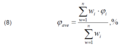
where: φave – annual average power utilisation factor of wind turbine, wi – wind instant speed.
These results confirm that turbine of 2100 W power is the best choice among turbines with horizontal rotation axis. Average annual value of this parameter involves taking account of wind distribution throughout the whole year, hence, it is a criterion that accurately determines the efficiency of the device.
Table 1. Annual average power utilisation factor of turbine with horizontal rotation axis

Analysis according to exactly the same algorithm was performed for machines with vertical rotation axis. Selection was made among numerous products within the power range of between 500W and 4000 W. The results are shown in Figure 5. The nominal power corresponding to each plot can be found in Table 2. Due to low start-up speed, the turbine of 500 W power has a very good characteristic, achieving nominal power with wind speed of 8÷9 m/s.

Like before, average annual value of φave parameter was calculated, being 8.95% in case of the best of turbines of this type. The values for turbines with vertical rotation axis are shown in Table 2.
Table 2. Annual average power utilisation factor of turbine with vertical rotation axis

The adopted selection criterion allowed to choose such models among home wind power plants, as are characterised with maximum use of atmospheric conditions occurring in the given area. For turbines with horizontal rotation axis it is a turbine with nominal power of 2100 W, whereas in case of vertical rotation axis it is a turbine with nominal power of 500 W. Figure 6 shows comparison of capacity utilisation factors for the aforementioned machines. The turbine with horizontal rotation axis has better characteristics of power utilisation as this factor increases faster the greater the wind speed.

Wind turbine installation gains
Figure 7. shows day sums of heat obtained for two turbines characterised with the highest utilisation factor. It is worth noticing that in case of Wroclaw area there is a great discrepancy as far as obtained heat is concerned. For 500 W turbine, minimum amount of heat is 0.11 MJ/day, and for 2100W turbine it is 0.29 MJ/day. Maximum heat amounts are 22.37 MJ/day and 134.86 MJ/day respectively.

Knowing that daily amount of heat required to heat up water per one person is usually about 10÷15 MJ, one can notice that the heat obtained in extreme cases will not cover the needs of one person (even when 20 such machines are used) or will supply twice as much heat as is required by a 4-person family.
If the wind turbine system is used also to cover the demand for electricity or possible sale, than we are basically skipping the problem of selecting wind turbine power. Due to significant cost of inverter, charge controller, accumulator, etc., it could economically more viable to use wind turbine for DHW purpose. In such a case there is a need to select wind turbine power accurately.
If the system is not equipped with additional heating device, then the heat obtained from wind turbine should cover DHW demand on every day of the year. As has been proven before – such a solution is barely possible, and definitely unprofitable due to large amounts of unused heat during the days when the values of obtained heat significantly exceed the demand.

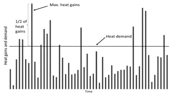
If the system of DHW preparation is equipped with additional heating devices, then the greatest economic profit is achieved by selecting wind turbine in such a way that the maximum amount of heat obtained during a day does not exceed daily demand for water, as has been shown in Figure 8. There will be no unused energy as a result, which will shorten the time of return on investment.
In order to increase the percentage of demand covered by the system it is possible to select greater power of wind turbine. However, this power should be limited with the maximum daily heat amount that can be accumulated in the DHW tank. If we assume that the temperature of feed water is 10 ⁰C and that of domestic water is 50 ⁰C, heat is accumulated by using heat capacity of water, when it is heated by 40 ⁰C. As a result, it is possible to store heat in the accumulative tank by heating water to 90 ⁰C, for instance. In consequence, the amount of accumulated heat can be twice as big as the amount assumed initially when the tank was selected, as has been shown in Figure 9.
Summary and conclusions
The article shows advantages of using wind turbines for heating DHW. A diagram has been shown and components have been listed. In selection analysis, the authors have shown the way of determining heat necessary for preparing DHW They have also mentioned losses occurring in the installation and provided the ways of calculating them. In the analysis of the values that affect the choice of wind turbine for DHW installation, it has been shown that there are a few parameters constituting criteria for the selection of wind turbines Power utilisation factor was considered the most important criterion. Other values include: the speed of wind in the given area that determines the utilisation factor; power characteristics of the wind turbine and the demand for heat.
The analysis conducted allows to draw the following conclusions:
– nominal power and power characteristic are not good criteria for selecting wind turbines for DHW installation,
– the speed of wind in the given area is an important parameter of the assessment whether a wind turbine is usable in the given geographic region, so power utilisation factor should be considered the most important parameter dependent on the speed of wind,
– when selecting wind turbine power, one must take account of the value of heat demand for preparation of DHW and the DHW tank’s accumulation capacity.
Acknowledgments: This work is sponsored by Ministry of Science and Higher Education in Poland under the grant for Wroclaw University of Science and Technology. Project No 0402/0157/17.
REFERENCES
[1] Żabicki D., Przydomowe elektrownie wiatrowe, Czysta Energia, nr 11/2013
[2] Erich Hau, Wind Turbines: Fundamentals, Technologies, Application, Economics, 2nd edition, Springer-Verlag, Berlin Heidelberg 2006
[3] Tytko R., Małe elektrownie wiatrowe (MEW), Czysta Energia, 2/2010
[4] Johnson G., Wind Energy Systems, Electronic Edition, New York, 2001
[5] Koczyk E., Ogrzewnictwo praktyczne, Systherm, Poznań 2009
[6] Wood D., Small Wind Turbines, Analysis, Design, and Application, Springer-Verlag, London Limited 2011
[7] The Ordinance of the Minister of Transport, Construction and Maritime Economy of 5 July 2013 amending the ordinance on technical conditions which must be fulfilled by buildings and their locations, Journal of Laws of 13/8/2013. No. 926 (in Polish)
[8] The Ordinance of the Minister of Infrastructure of 3 June 2013 on the methodology for calculating the energy performance of buildings and flats or parts of building constituting an independent technical and functional entity and the method of drawing up and samples of their energy performance certificates. Journal of Laws No 2014, item 888 (in Polish)
[9] Zimny J., Renewable sources of energy in energy-efficient constructions, Polish Geothermal Association, Krakow 2010 (in Polish)
[10] Nemś A., Nemś M., Analysis and selection criteria of photovoltaic panels for DHW, 4th Scientific and Technical Conference on Modern Technologies and Energy Systems, WTiUE 2016, E3S Web Conf., 03003 (2017), Vol.13, 1-7
[11] Szymański B., Małe instalacje fotowoltaiczne, Wydanie I, GLOBEnergia, Kraków 2013
[12] Stiebler M., Wind Energy Systems for Electric Power Generation, Springer-Verlag, Berlin Heidelberg 2008
[13] Cichoń A., Malinowski P., Mazurek W., Porównanie możliwości wykorzystania małych turbin wiatrowych o poziomej i pionowej osi obrotu, Przegląd Elektrotechniczny, 92 (2016), nr.9, 262-266
[14] Hau E., Langenbrinck J., Palz W., WEGA Large Wind Turbines, Springer-Verlag Berlin Heidelberg 1993
[15] Boczar T., Energetyka wiatrowa, Aktualne możliwości wykorzystania, Wydanie drugie, Warszawa, Wyd. Pomiary Automatyka Kontrola, 2008
[16] Emission factors and calorific values of fuel as well as typical meteorological years and statistical climate data for energy performance calculations. http://mib.gov.pl/2- Wskazniki_emisji_wartosci_opalowe_paliwa.htm# (in Polish)
[17] Mazur M., Partyka J., Marcewicz T., Analiza zastosowania hybrydowego systemu zasilania odnawialnej energetyki wiatrowej i fotowoltaicznej w budynkach mieszkalnych, Przegląd Elektrotechniczny, 92 (2016), nr.8, 113-116
[18] Nalepa K., Miąskowski W., Pietkiewicz P., Piechocki J., Bogacz P., Poradnik małej energetyki wiatrowej, Olsztyn, 2011
[19] Malska W., Mazur D., Analiza wpływu prędkości wiatru na generację mocy na przykładzie farmy wiatrowej, Przegląd Elektrotechniczny, 93 (2017), nr.4, 54-57
[20] Baczyński D., Piotrowski P., Prognozowanie dobowej produkcji energii elektrycznej przez turbinę wiatrową z horyzontem 1 doby, Przegląd Elektrotechniczny, 90 (2014), nr.9, 113-117
Authors: PhD Eng. Artur Nemś, Wroclaw University of Science and Technology, Faculty of Mechanical and Power Engineering, ul. Wyb. Wyspianskiego 27, 50-370 Wroclaw, E-mail: artur.nems@pwr.edu.pl; PhD Eng. Magdalena Nemś, Wroclaw University of Science and Technology, Faculty of Mechanical and Power Engineering, ul. Wyb. Wyspianskiego 27, 50-370 Wroclaw, E-mail: magdalena.nems@pwr.edu.pl; Msc. Eng. Adam Ruziewicz, Wroclaw University of Science and Technology, Faculty of Mechanical and Power Engineering, ul. Wyb. Wyspianskiego 27, 50-370 Wroclaw, E-mail: adam.ruziewicz@pwr.edu.pl.
Source & Publisher Item Identifier: PRZEGLĄD ELEKTROTECHNICZNY, ISSN 0033-2097, R. 94 NR 4/2018. doi:10.15199/48.2018.04.36
