Published by Andrzej ŁEBKOWSKI, Gdynia Maritime University, Department of Ship Automation
Abstract. Electric vehicles (EVs) emerged as a next step in the evolution of transport technology. The article describes structure of system used for optimal management and monitoring of electric vehicle parameters, especially in regions of low possible ambient temperature. System can be used in all types of electric vehicles, such as: cars, ATVs, motorbikes, scooters, bicycles or boats. Application of GSM/GPS technologies allows remote monitoring of state and management of vehicle battery thermal aids (increasing battery performance and longevity while reducing operating costs) as well as control of vehicle to grid and grid to vehicle energy flow in smart grid systems. System functions were tested on an electric vehicle in normal road conditions at a period of ambient temperature reaching -25°C (-13°F). Article contains road tests results along with comments on possible benefits that may be derived from the application of the system in practice. (System zarządzania pakietem akumulatorów w pojeździe z napędem elektrycznym).
Streszczenie. Pojazdy elektryczne stanowią następny krok w ewolucji technologii transportu. Artykuł przedstawia strukturę systemu do optymalnego zarządzania i monitorowania parametrów pojazdu elektrycznego, szczególnie w warunkach niskiej temperatury otoczenia. Typy obsługiwanych pojazdów obejmują samochody, quady, motocykle, skutery, rowery elektryczne oraz łodzie. Zastosowanie technologii GSM i GPS umożliwia zdalny monitoring i zarządzanie modułem ogrzewania akumulatorów a także kontrolę przepływu energii z sieci do baterii I baterii do sieci (smart grid). Funkcje systemu zostały przetestowane w warunkach drogowych przy temperaturach dochodzących do -25°C. Artykuł zawiera wyniki badań wraz z omówieniem potencjalnych korzyści wynikających z zastosowania opisanego systemu.
Słowa kluczowe: pojazdy elektryczne, system zarządzania akumulatorami, akumulatory litowe, termiczne kondycjonowanie akumulatorów
Keywords: electric vehicles (EV), battery management systems (BMS), lithium batteries (Li-Ion, LiFePO4, LTO), thermal management
Introduction
Car sales statistics show, that there is a growing trend in sale of vehicles having electric propulsion [1-3]. The reasons of this behavior are undoubtedly the advantages of using such a vehicle: decreased energy consumption, limited noise emission, lower operating costs, social prestige. Additionally, regulations in certain countries can influence owners to buy this specific car variety, by virtue of: motor insurance discounts, free of charge motorways and parkings in city centres, access to separate bus-lanes, possibility of free battery recharging in public charge stations. The main factors influencing purchase decision are ecology and economy of use. Customers have a wide choice of vehicles offered by reputable dealer networks or by less known makes, as well as a possibility of conversion of internal combustion engine car to electric propulsion either by themselves or in specialized car shops. No matter which choice, users of such vehicles want to have full control over it, i.e. know whether the battery is charged, if the vehicle can or cannot be used (for example due to bad battery condition or malfunction of some component).
This paper tries to present a system to manage an electric vehicle being it a car, an ATV, a motorbike, a scooter, a bicycle or a boat. Application of Management System for Electric Vehicle – (MSEV) can greatly improve the electric vehicle battery performance. Its impact can be highest in vehicles operating during low ambient temperature conditions, when outside air temperature drops below 0°C (32°F). While the individual cells in the electric vehicle are cold, and their temperature is less than 0°C (32°F), they can be easily damaged. Additionally, their performance suffers as the temperature drops [5-7]. The phenomena of battery longevity, performance and efficiency decrease as a function of dropping temperature are well known and were the subject of many articles.
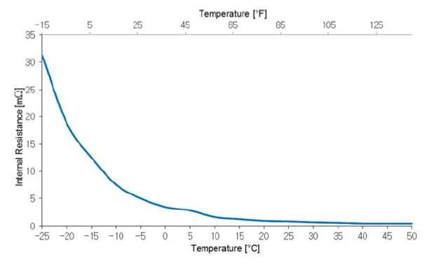
The probability of cell damage is the greater, the ambient temperature is lower (Fig.1). The vehicle range is also becoming severely limited. Electric vehicle users accustomed to driving every day, during cold periods of ambient temperature 0°C (32°F) or lower will, at first, notice the reduced reading of on-board potential range gauges. Only after the self-heating process takes place due to battery discharge, the temperature inside the battery will raise to nominal value. The operation of such vehicle should take place with battery temperature (previously chilled by the cold environment) at nominal value, while this temperature will be achieved probably when the vehicle and its user have reached the destination. If the vehicle two-way charger will not be plugged-in, the battery’s temperature will again drop to low temperature of the surrounding air.
Another important matter is that charging a battery in low temperature conditions limits its ability to absorb electric charge. Charging any cold battery severely limits its operating life, including lithium batteries in which the low temperature aging mechanism caused by lithium buildup on negative electrode is present. This mechanism, along with low temperature and a vehicle not fitted with battery heating system suggests a need to reduce the setting of BMS system charging voltage to a lower value, thus allowing the two-way charger to proceed without greatly reducing the battery’s State Of Health (SOH) (e.g. as recommended in [4,8] 0,25C, 3,55V for LiFePO4 cells). During the tests conducted by the author it was observed that when the ambient temperature was below 0°C (32°F), the battery’s ability to supply energy became limited. During operation in said conditions, a considerable voltage drop is observed when the battery is loaded. When the voltage drop under load exceeds 2V, in case of LiFePO4 cell, while its nominal value is about 3.2V, the irreversible chantestinge in electrochemical internal structure of the cell takes place which results in permanent micro-damage. This phenomenon can be compared to a fuel tank with a small hole, through which the fuel seeps out. In the case of a battery, the low temperature combined with high load causes micro-damage. The cell’s internal resistance is increasing which reduces State Of Health (SOH) and State Of Charge (SOC) [9-12]. The solution would be to install a battery heating system, which consumes a relatively small amount of electrical energy in relation to the benefits such as better battery efficiency translating into better vehicle range and greater available power from the drivetrain. Such a system, combined GSM/GPS monitoring system (Fig.2) can provide very efficient battery electric vehicle operation.

Using GSM/GPS technology, the user can monitor the state of battery at any moment, as well as control its operation e.g. turn on the charging process or turn on the heating system. Additionally, thanks to simple and inexpensive heating elements the system can be applied to virtually every electric vehicle containing a battery. Components of MSEV using elements of AI (Artificial Intelligence) processing, such as fuzzy logic or expert system database can influence optimal utilization of battery electric vehicle in low ambient temperature conditions.
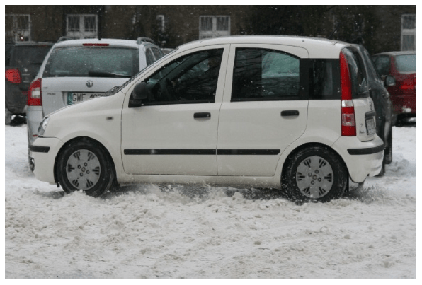
The system can for example check the weather forecast and, if the forecast reports possible temperature drop, it can then request the user to plug in the vehicle to charging socket. Depending on the outside temperature the MSEV can in the first place heat up the battery pack and then commence its charging. With the charging finished, it can proceed according to program defined by the user – either maintain the pack’s temperature at the level which enables driving, or preheat the battery to be ready to drive at the selected time. The scope of work and MSEV research results presented in this paper have demonstrated its usefulness and validity of its use in battery electric vehicles in which the manufacturer did not anticipate battery heating, especially if the vehicle is operated in geographic regions with ambient temperatures often less than 0°C (32°F). System testing was conducted in real driving conditions on Fiat Panda electric vehicles built in Gdynia Maritime University (Fig.3).
While the MSEV was tested in cars, its simple design and available functions allows it to be used in any electric vehicle, be it a motorbike, an ATV, a scooter, a bicycle or a boat.
MSEV functions
Postulated Management System for Electric Vehicle – (MSEV) can be used for mass produced vehicles, as well as for small-lot produced and converted from ICE propulsion.
Selection of possible system functions depends only on what the user will want to manage and monitor. MSEV can be used for remote monitoring, alarming and diagnostics of each vehicle component and for logging of any parameters using GSM/GPS technology through any cell phone using SMS messages. Applied technical means allow the user to read out the battery pack parameters or to control the operation of the two-way charger. The user can configure the system to send him an SMS with vehicle parameters to a predefined phone number. The main point of this technical solution is to fulfill goals including:
• monitoring of parameters vital from the perspective of its user,
• remote control of subsystems e.g.: battery charging system compatible with smart grids (V2G – vehicle to grid mode, G2V – grid to vehicle mode), battery heating system, cabin heating system,
• alarming (SMS on mobile), in case of exceeding nominal value of parameters e.g.: main battery Depth of Discharge (DOD), auxiliary 12V battery DOD, high/low battery temperature,
• requesting the user to take some action e.g. request for plugging in the vehicle to the power grid after checking the weather forecast in order to power the battery heating system,
• alarming in case of attempted access by unauthorized persons or burglary,
• widely understood diagnostics associated with the estimation of individual parameters from measured signals,
• logging of vehicle components’ parameters,
• logging of vehicle location and motion parameters,
• remote monitoring of vehicle and it’s components parameters and operation.
MSEV finds use in acquisition of many parameters describing state of an electric vehicle. Application of GSM/GPS technology allows remote monitoring of these parameters and remote control of executive and measurement modules of the vehicle. The main part of MSEV is a Central Processing Unit (CPU) containing microprocessor controlling vehicle parameters, supplied from on board 12V power. CPU gathers signals from various onboard sensors: battery voltage sensor, battery charge current sensor, motor supply current sensor, auxiliary supply current sensor, motor temperature sensor, battery temperature sensor, ambient temperature sensor, vehicle speed and distance traveled sensor, accelerometers and gyros, door switches and other anti-burglary sensors. It can also request the driver to input the approximate distance he is planning to travel, and ask the driver’s permission to become a part of a smart grid. The CPU also communicates with internal GSM and GPS modules, internal self-diagnostic module and has backup power system. Additionally, the MSEV CPU communicates with other vehicle components, including: two-way charger control block, main battery heating system, user interface (including remote monitoring), data recording device (flash card, USB flash drive, etc.), OBD-II or similar external diagnostic system, emergency power system, additional traction battery/power source (range extender).
The MSEV contains large scale of integration electronic components and easy to install sensors and modules. The optimal use of electric vehicle is possible, thanks to sensors, executive/measurement modules, reference values for each vehicle parameters stored in internal database and artificial intelligence contained within device programming and via cooperation with vehicle subsystems.
This cooperation can lead especially to:
• proper operation of main traction battery through automatic and maintenance-free control of vehicle two-way charger,
• logging of all measured parameters,
• estimation of vehicle parameters, like: amount of energy in main battery, vehicle range, etc.,
• informing the user about vehicle state through user interface and GSM communication module,
• informing the user about distance and location of closest charging station,
• monitoring the state of main battery and control of systems prolonging its useful life, like cooling or heating systems,
• possibility of remotely informing the user about the vehicle whereabouts and its parameters (voltages, currents, temperatures, SOC, etc.),
• possibility of asking the user to perform some action e.g. requesting plugging in the vehicle to the power socket after checking the weather forecast in order to power the battery heating system,
• possibility of changing the BMS settings depending of battery pack temperature,
• feature of turning on the two-way charger during the night, when the electricity price is much lower (for example between 10 PM and 6 AM),
• possibility of smart grid integration – using the vehicle battery as an electrical grid energy buffer,
• warning the user in case of vehicle malfunction or fire hazard.
MSEV structure
MSEV structure is presented on figure 4 showing block diagram embedded in vehicle side silhouette view. MSEV contains on board microprocessor CPU, which can communicate with vehicle user through user interface and with external systems for diagnosis and log download through external port. Using data from on board sensors and devices: distance travelled and speed sensor, traction motor voltage sensor, traction motor current sensor, traction motor temperature sensor, battery pack temperature sensor, battery pack voltage sensor, ambient temperature sensor, extender (additional battery pack or power generator) it is possible to estimate the remaining power in main battery. Additionally, data from sensors: distance travelled and speed sensor, traction motor voltage sensor, traction motor current sensor, traction motor temperature sensor, battery pack temperature sensor, battery pack voltage sensor, battery pack charging current sensor, ambient temperature sensor, range extender (additional battery pack or power generator) (Fig.4) allows estimation of remaining vehicle range. The vehicle range is estimated from the current reading by the current sensor located on the power wiring supplying the onboard devices and drivetrain, and by the temperature reading of battery pack reported by temperature sensor.
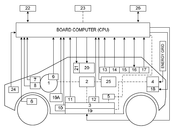
1. vehicle traction motor/motors, 2. power inverter (DC/AC, DC/DC), 3. electrical energy reservoir (battery pack), 4. two-way charger, 5. 12VDC power supply (12V battery or DC/DC inverter), 6. distance travelled and speed sensor, 7. traction motor voltage sensor, 8. traction motor current sensor, 9. traction motor temperature sensor, 10. battery pack temperature sensor, 11. battery pack voltage sensor, 12. battery pack charging current sensor, 13. angular acceleration sensor (gyro), 14. accelerometer sensor, 15. GPS module, 16. GSM module, 17. ambient temperature sensor, 18. on board two-way charger control system, 19. battery pack with heating/cooling module, 19A. vehicle cabin heating/cooling module, 20. user communication interface, 21. communication port for parameters recording (SD card, USB, etc.), 22. communication interface for external devices (PC, external database, etc.), 23. power supply system, 24. door switches and anti-burglary sensors,25. range extender (additional battery pack or power generator), 26. self-diagnostic module
The CPU processes data from the above mentioned sensors so it can warn the user, using the user interface, about exceeding the value of critical vehicle parameters including: low voltage of main battery, motor overcurrent, low vehicle range due to low remaining charge in main battery, as well as inform the user about the state of all parameters measured by and estimated from sensor data including total distance travelled since system installation, distance travelled since last charge, distance possible to travel using energy remaining in main battery and additional power source. CPU can also indicate the distance and whereabouts of closest charging station using internal location database.
The MSEV can, using the GSM module, alert the user remotely about exceeding critical parameter values, such as: low voltage of main battery, low vehicle range due to low remaining charge in main battery, exceeding operational parameter values e.g. motor overcurrent, vehicle overspeed, vehicle operation outside of designated area. Besides transmitting parameter values it is possible to monitor the state of all vehicle components using internal vehicle network. User can access the parameters of devices including motor controller, two-way charger, Battery Management System including individual cell data (voltages, temperatures), battery heating system, cabin heating system, power braking system, etc.
The CPU computer board consists of an Atmel Atmega324PA microcontroller and peripheral devices including: GPS module FGPMMOSL3, GSM module ZTE MG3030, real-time clock PCF8583, serial port expander PCA9555D, analog switches ADG707, voltage to frequency converter LM331, operational amplifier LM358D, isolating DC/DC converters type AM1D, relays, Dallas temperature sensors type DS18B20, HD44780 compatible alphanumeric LCD module, and numerous passive devices. The part of computer board structure responsible for conditioning the battery pack is presented in figure 5.
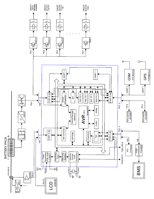
Application of external electronic modules such as GSM modem, GPS module or RTC clock requires use of hardware communication busses. The chosen microcontroller contains all required serial busses. The project uses USART interface to communicate with GSM modem and GPS module and two wire TWI interface to communicate with RTC clock chip.
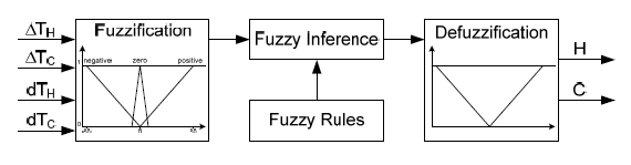
Artificial Intelligence methods, such as fuzzy logic, used in the MSEV are used mostly in conjunction with the battery pack temperature control process. Usefulness of these methods in control applications using a microcontroller was proven in [13-15]. Because a fuzzy logic temperature controller is not a topic of this paper, it will be presented very briefly. During the non-linear process of electric vehicle battery pack temperature control, there are 2 input variables, for a system with only battery heating, or 3 input variables, for a system with both battery heating and cooling. In a “heating only” system, these variables are: the difference between the setpoint temperature of the battery pack, to which is should be heated and its real temperature – a mean of two battery packs temperatures ΔTH (ΔTH = THset – Tactual) and derivative of this difference dTH. In a system with both heating and cooling, these variables are: a difference between setpoint heating temperature of the battery pack and its real temperature – a mean of two battery packs temperatures ΔTH, a difference between setpoint temperature to which the battery pack should be cooled and its real temperature (a mean of two battery packs temperatures) ΔTC (ΔTC = – (TCset – Tactual)) and a derivative of temperature difference dTC. The output variables of fuzzy temperature regulator are called H (Heating) and C (Cooling), they control respectively the duty cycle of the heating mats transistor (battery pack heating) and the battery pack cooling system transistor (controlling e.g.: a fan, a Peltier Cooling Module, a liquid cooling system). The complete algorithm consists of only three main steps: fuzzification of input variables, inference, and defuzzification.
The first step is implemented in fuzzification block, its goal is to evaluate and transfer the information from the quantity domain (difference of setpoint and real temperature ΔT of two battery packs) into the quality domain as a mapping of given variable into available fuzzy sets (Fig.6). The next step (inference) is an operation of deciding on inclusion of given variable into given fuzzy set, based on rules input by an expert into the inference database. The inference is based on simple IF-AND-THEN rules. IF (ΔTL is Neg.) AND (dTH is Neg.) THEN (C is Negative) The last step of fuzzy regulator operation (defuzzification) is to define a crisp value of output variable H or C, defining the operating time of heating mats or cooling system, which is correct from the point of view of input variables ΔTH or ΔTC and corresponding changes dTH or dTH. In the system in question overshoot in set temperature does not create negative consequences, because higher temperature in the given range has a positive effect on the battery pack operation. The structure of a fuzzy logic battery pack temperature controller using a microcontroller is very simple, which allows its easy implementation and reliable operation.
The elements of artificial intelligence that were used in the design are meant to provide optimal operation of the electric vehicle (such as: charging the battery pack in an optimal way, with the lowest grid electricity cost, and at a best possible temperature). Applied algorithms governing the operation of the battery pack are equipped with elements of artificial intelligence, such as cognitive system supporting the operation of the electric vehicle.

The task of the cognitive system is to support optimal utilization of the battery pack based on the conditions stored in the knowledge base of the system, e.g. time of day in which electricity is at lower price, the time bounds on allowed smart operation, or vehicle’s user behavior e.g. determination that user usually drives the vehicle between 6:00-8:00 AM and 4:00-6:00 PM on weekdays and between 10 AM and 4 PM on weekends. The cognitive database can be modified by the user according to his preferences and habits. It gives the smart grid system operators knowledge, if and when the particular vehicle can become a part of a smart grid. The system is designed in order to maximally simplify the operation with the smart grid, and the only driver’s task is to physically connect the vehicle into the wall socket. The intelligent algorithms will allow, apart from a regular charging mode, an automatic mode where the charging would only take place in periods when the electricity price is lowest. The algorithm would also take care of the battery health and maximize its life span. These goals would be met by application of procedures allowing the charging process only when the circumstances will be optimal. By optimal, meaning: the proper future temperature of the battery, based on weather forecast data, the time of charging depending on the defined periods of vehicle operation during the day. The battery two-way charger plays a significant role in the system, as it need the capacity for two-way energy flow – from the grid to the battery during charging mode (G2V) and from the battery to the grid during the smart grid buffer mode (V2G).
The mobile application will allow the user to define the level of energy to remain in the battery in a given day at a given time. The energy level impacts directly the achievable range in particular conditions (geographic location, weather conditions). The cognitive system algorithms shall choose the operational parameters in an optimal way – by minimizing the battery Depth of Discharge (DOD) and maximizing the State of Health (SOH), by maximizing the financial gains from the trade of energy with the smart grid, maximizing the user’s own priorities (e.g. powering his own buildings in the first place).
The MSEV system is designed to create a synergy effect in a whole group of electric vehicles operating at a given region, creating and intelligent network of fully electric vehicles (EV), plug-in hybrid electric vehicles (PHEV), and fuel cell electric vehicles (FCEV).
Experimental – MSEV road tests
Due to the fact, that a smart grid monitoring station which would globally manage the energy flow has not yet been created, the MSEV could not use the smart grid functions of V2G mode and they have not been included in the tests. The testing however included the battery heating system, and it have been tested on a FIAT PANDA EV vehicle. Several such vehicles were built in Gdynia Maritime University (please refer to website at http://evpl.pl). The tested vehicle uses LiFePO4 cells and synchronous AC motor. The vehicle’s top range is about 160km (100 miles) and top speed is 170 km/h (105 mph). Testing was conducted for a period of 3 years (about 1100 trips) in normal road conditions [16,17].
The tested vehicle had two LiFePO4 battery containers with heating system. Containers were made from sheet steel, one was located in the front of the car, under the hood while the other was located in the rear, below the trunk floor. The location of both containers is presented in figure 7.
Heating units with a combined power of about 400W were installed under the battery packs as heating mats made with heating cables laid out on a rubber base. Next, the heating cables were potted in thermally conductive rubber compound, with the heat flux conductivity of about 1,6W/m∙K. Such prepared mats were located on the bottom of battery containers as shown in figure 8.
The advantage of the proposed solution in relation to systems with liquid battery pack temperature control is its simple design. As stated in the introduction, this system can be used in all kinds of vehicles in which the manufacturer did not plan any battery heating system. It can be argued, whether such system can compete with liquid based systems which allow both heating and cooling of battery packs. The performed research of MSEV have proven that for geographical regions where large drops of temperature occur in the winter meaning periods of temperature below 0°C (32°F), and the temperature during the summer not exceeding 35°C (95°F), the MSEV performs adequately allowing the vehicle to achieve higher range in low ambient temperature conditions than without such a system.

During the tests in the summer, when the air temperature had reached 35°C (95°F), the battery pack’s maximal temperature was on the order of 50°C (122°F), which is a safe maximal value for LiFePO4 cells.
During the tests the installation of battery container cooling system based on Peltier effect modules (surface mounted) was considered, but it was eventually ruled unnecessary.
Plot of vehicle range of heating mats were also tested, the first where they were placed around the batteries instead of on the bottom, and another one where the heating cable was wrapped around the batteries without any potting compound. The most beneficial results of reheating the batteries were obtained for mats made of heating cables potted in thermally conductive rubber compound, arranged under the batteries.
Data on the battery pack temperature is gathered from several temperature sensors located in the battery container. Because the heating cable is a resistive-type electrical load it is possible to supply it either from the batteries itself, or from the mains supply after plugging in. This feature enables the battery heating system to perform with no losses in comparison to liquid systems where the flow of the coolant is circulated by pumps requiring additional electric power. Additionally, liquid based systems consume greater volume than heating cables, their design is generally much more complicated and they contain more failure-prone elements. Their mass is greater, they require periodic maintenance and service (checking the coolant level and topping off) too. They are also vulnerable to mechanical damage which can lead to leaks and loss of coolant in the circuit. The alternative is to use the internal heating methods using alternating current [18].
The best solution for a battery electric vehicle would be to use batteries which would be truly low temperature proof [19], safe in general use, fast to charge and having an energy density of at least 1000 Wh/kg. Presently available lithium batteries e.g. LiFePO4 have energy density of about 95 Wh/kg, Li-Ion 85Wh/kg, and upcoming LTO cells have 160 Wh/kg. The most important advantage of postulated solution is that MSEV contains battery temperature control module with possibility of active heating.
Optimal temperature range for use of Li-Ion battery lies between 15-35°C (59-95°F). For LiFePO4 battery the optimal temperature range of is slightly wider (Fig.1) [4].
The most important matter influencing long battery service life (the largest possible cycle count) is the voltage range between charge and discharge. Basing on data from road tests, it can be concluded that the maximal life of LiFePO4 cells can be reached at single cell voltage range between 2.80-3.65V. Furthermore, the terrain in which the vehicle is operating (hills or flat) has also its effect on the number of battery cycles. Shorter operating life is also expected in vehicles operated in sporty – aggressive driving style, associated with frequent acceleration and hard braking. Finally, the charging current and the used BMS type (active, passive) are affecting the number of cycles. The best results come with the use of active BMS and charging current no higher than 0.5C.
If the vehicle is used in region where ambient temperature during winter drops to no less than 10°C (50°F) for short periods, the user practically will not feel much of a difference in the range achieved by his vehicle. In regions with more severe winter temperatures of -20°C (-4°F), the use of electric vehicle becomes troublesome because range becomes limited to about 40-50% of nominal.
Decrease in range comes not from the use of cabin heating, which depending on the particular vehicle consumes from 0.2kW up to 4kW, but rather from the physicochemical processes taking place in the battery at low temperatures. Likewise, battery temperature higher than 50°C (122°F) could result in permanent, nonrecoverable changes in the structure of its cells. The answer to this problem is the battery heating system. The simplest solution is the application of properly placed heating cables widely used in underfloor heating or rain gutter thawing. Heating wires can be applied on the bottom of battery box or on its sides between cells and box walls. The power required for maintaining the battery pack’s temperature of 10°C (50°F) is about 0.3kW. For lithium batteries, depending on their type, the assumed loss of capacity can be on the order of 7-10% for 10°C drop from reference value at 25°C (77°F). At such assumptions, it can be calculated that battery capacity at 0°C (32°F) would be 80% nominal, at -10°C (14°F) about 70%, and at temperatures reaching -20°C (-4°F) only about 60% nominal capacity. If we take into account the necessary operation of cabin heating at such temperatures, after accounting for all the factors, it may turn out that effective possible range in such temperature conditions could be only 30-40% of range normally achieved by the vehicle. In case of lead-acid batteries, the drop in range is even more severe.
Taking into consideration the operating conditions of electric vehicle at low ambient temperature, it could turn out, that such operation is economically unwise. All the more, battery life at low temperature degenerates much faster and its life can be possibly halved. It is therefore recommended to use a battery heating system in an electric vehicle. Heating can be accomplished in a few ways, for instance by liquid circulation system used normally for cell cooling, by addition of a heating element or by utilization of heating mats properly sized for the battery pack. In case of liquid heating, the most straightforward solution would be to install an electric heater powered by the same mains supply used to power vehicle two-way charger. It has to be considered, that during charging the batteries heat up themselves, so the system should control the heating to keep the battery temperature in optimal range.
The vehicle, which battery was heated during charging and subsequent stationary state would achieve greater range than a vehicle operating in identical conditions, but with unheated battery. The process of battery degradation due to use at lower temperature would also be less noticeable. The heater used in heating/cooling loop can be additionally powered from the battery itself during the vehicle operation, after proper modification of the vehicle’s electrical wiring and required voltage matching. The system using heating mats works on the same principle, heat source can be powered either from mains supply or from vehicle battery while traveling.
Provided that for battery heating during vehicle movement, the energy of 0.2-0.4 kWh would be spent, the vehicle would achieve range close to its maximum. During the construction of battery heating system, the process of cell self-heating was taken into account. The self-heating process stems from entropy change during electrochemical reactions [20,21] and from Joule heating due to current flow. The amount of heat generated in battery pack can be determined from the approximate equation (1).

where: q – indicator of generated heat (W); n – number of cells; i – current flowing through cells (A); r – cell internal resistance (Ω); T – temperature (K); B – temperature coefficient dependent on cell voltage drop and temperature rise caused by that drop (V/K).
The testing period encompassed an entire year, which allowed acquiring data on vehicle and its battery performance in many different conditions and situations. The car under test was driven with various driving styles from 100% charged condition to the moment the onboard BMS system indicated, that the battery was completely discharged. The data was recorded using a recorder described in [22]. Every voyage recording was then analyzed and compiled into table 1 and figure 9.
The postulated MSEV solution seems to be justified, especially concerning the fact that without it, the vehicle operating in identical conditions would have its range limited by about 30-40%. Thanks to battery heating system the performance and efficiency of whole battery pack is increased.
Table 1 and figure 9 show relationship of obtained vehicle range depending on battery pack temperature. The MSEV’s battery control capability was also tested. The plot shows operating conditions: operation without turning on of the vehicle’s auxiliary systems (curves 1 and 2) where curve 1 shows the maximal achieved range (best case) during testing at a particular temperature; curve 4 shows operation with cabin cooling/heating turned on; curve 3 shows operation with battery heating turned on; curve 5 shows operation with battery heating and cabin cooling/heating turned on. From the data on the plot it can be observed, that use of the battery heating system can increase vehicle range in comparison to identical conditions where heating system was inactive or not present.
The table 1 contains the basic parameters of the batteries used in electric vehicles.
Table 1. Vehicle range as a function of temperature
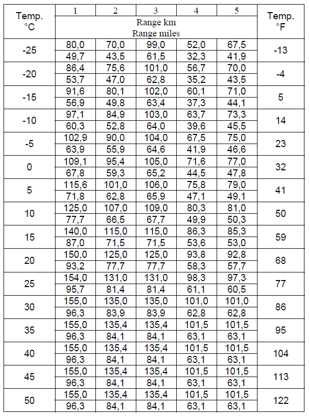
The presented research shows that application of battery heating system in low ambient temperature can increase vehicle range by more than 30%. Bearing in mind the average vehicle range of 100-130km (60-80 miles), the loss of 30-40km (18-25 miles) can have considerable impact on during long voyages.
Another important issue from the point of view of electric vehicle operation is the positive impact of application of battery heating system resulting in significant increase in cycle count achieved during battery life.
Use of electric vehicle in low ambient temperature without the battery heater can cut the lifetime of the battery even by half [4]. In this case, the battery replacement implies significant costs which add up to the total operating cost of the electric vehicle. Speaking of EV operating cost, utilization of the MSEV can cut these even by half. This effect can be obtained by charging the vehicle only at a time when energy from the grid is cheaper.
For instance, in Poland, one kilowatt-hour (kWh) of electrical energy during the day costs about 20 USA cents, whereas during the night between 10PM and 6AM it’s worth only 10 cents. Therefore, it pays to use the MSEV thanks to which the user can wirelessly monitor the vehicle state using GSM/SMS technology.
During the road tests, at the beginning most users plugged in their vehicle in order to charge it almost immediately after returning home from work (at 4-5 PM). As a result, the battery was charged for at most 8 hours, and had finished charging till midnight. The charging took place during the time of higher electricity price for 6 hours, and only at most 2 hours during the lower price time period. It has to be stated, that during the road tests, very rarely was the battery discharged completely, so almost all the energy replaced in the battery was the energy with the higher price. Charging the battery during the time of lower electricity price by using the MSEV’s function of automatic two-way charger start in user controlled intervals could reduce the charging cost by about 60% (8 hours of charging during low electricity price period).
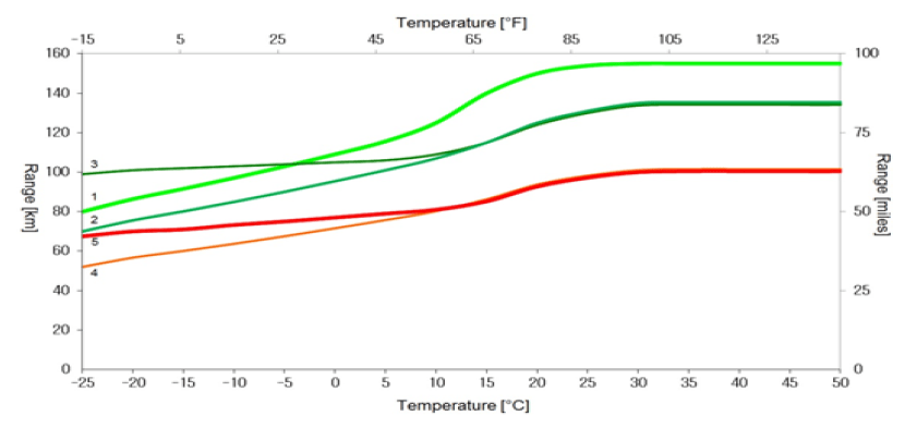
1 – maximum range (best case) achieved by vehicle with auxiliary systems turned off; 2 – average range achieved by vehicle with auxiliary systems turned off; 3 – average range, operation with battery heating turned on; 4 – average range, operation with cabin cooling/heating turned on; 5 – average range, operation with battery heating and cabin cooling/heating turned on
The advantage of MSEV is that the user can control and monitor the vehicle parameters (battery voltage, ambient, battery and cabin temperature; charging current and state; cabin heating, vehicle position and speed, etc.) using his GSM mobile phone. The user can also configure the MSEV in a way to automatically initiate the charging process or turn on the cabin heating so the travel can be made in the comfort of warm cabin right from the start. The MSEV can turn on battery heating automatically in case the ambient temperature drops below set value. Using data from sensors and GPS, the MSEV can inform the user remotely by the GSM network about vehicle location and state (voltages, currents, temperatures, etc.) Additionally, the MSEV can remotely alert the user about on board fire hazard.
Summary
This work wants to present an alternative mean of battery electric vehicle operation. It presents the results of tests of battery pack operating in low temperature environment. Thanks to the MSEV, a stress free operation of electric vehicle is possible, being it a car, an ATV, a motorbike, a scooter, a bicycle or a boat. The system functions permit vehicle use both in moderate and extreme temperature conditions, where -25°C (-15°F) ambient temperature is occurring. The use of GSM/GPS modules allows permanent monitoring of vehicle parameters as well as its remote control which can lead e.g. to charging cost reduction, by charging during hours when price of electric power is lower.
Using Artificial Intelligence methods residing inside the computer board, such as fuzzy logic or cognitive system it is possible to prevent damage to the battery which could potentially happen during use at low temperature environment and minimize the number of activities connected with the maintenance of the battery pack.
System can remotely check weather forecast and then request the user to plug the vehicle into the power socket to heat up the battery before driving.
According to the driver’s preference, the system allows to utilize the vehicle battery as an energy buffer for smart grid applications.
Application of the battery heating system increases comfort and passenger safety along with prolonging battery life which reduces total operation costs (approx. 60%) and increases time between battery replacements.
During the road tests (at low temperatures), a vehicle equipped with MSEV and battery heating system achieved 30% greater range than identical vehicle without such systems.
REFERENCES
[1] International Energy Agency. Global EV outlook 2016. Available: http://www.iea.org, (12.2016).
[2] Pontes J., Europe Electric Car Sales. Available: http://evobsession.com/electric-car-sales, (12.2016).
[3] Klippenstein M., Electric-Car Market Share In 2013: Understanding The Numbers Better. Available:
http://www.greencarreports.com/news/1089555_electric-carmarket-share-in-2013-understanding-the-numbers-better, (12.2016).
[4] Łebkowski A., Temperature, Overcharge and Short-Circuit Studies of Batteries Used in Electric Vehicles, Przegląd Elektrotechniczny, doi:10.15199/48.2017.05.13, (2017).
[5] Senyshyn A., Mühlbauer M.J., Dolotko O., Ehrenberg H., Lowtemperature performance of Li-ion batteries: The behavior of lithiated graphite, Journal of Power Sources, Volume 282, (2015), p. 235–240.
[6] Pesaran A., Santhanagopalan S., Kim G.H., Addressing the Impact of Temperature Extremes on Large Format Li-Ion Batteries for Vehicle Applications, 30th International Battery Seminar, Ft. Lauderdale, Florida, (2013).
[7] Wu B., Ren Y., Li N., LiFePO4 Cathode Material – Chapter 11, Electric Vehicles – The Benefits and Barriers, ISBN 978-953-307-287-6, (2011).
[8] Ouyang M., Chu Z., Lu L., Li J., Han X., Feng X., Liu G., Low temperature aging mechanism identification and lithium deposition in a large format lithium iron phosphate battery for different charge profiles, Journal of Power Sources, Volume 286, (2015), p.309–320.
[9] Wang Y., Zhang C., Chen Z., A method for state-of-charge estimation of LiFePO4 batteries at dynamic currents and temperatures using particle filter, Journal of Power Sources, Volume 279, (2015), p.306–311.
[10] Liu X., Wu J., Zhang C., Chen Z., A method for state of energy estimation of lithium-ion batteries at dynamic currents and temperatures, Journal of Power Sources, Volume 270, (2014), p.151–157.
[11] Zou Y., Hu X., Ma H., Li S.E., Combined State of Charge and State of Health estimation over lithium-ion battery cell cycle lifespan for electric vehicles”, Journal of Power Sources, Volume 273, (2015), p.793–803.
[12] Feng F., Lu R., Zhu C., A Combined State of Charge Estimation Method for Lithium-Ion Batteries Used in a Wide Ambient Temperature Range, Energies 2014, Volume 7, (2014), p.3004-3032.
[13] Isizoh A.N., Okide S.O., Anazia A.E., Ogu C.D., Temperature Control System Using Fuzzy Logic Technique, International Journal of Advanced Research in Artificial Intelligence (IJARAI), Volume1, No.3, (2012).
[14] Singhala P., Shah D.N., Patel B., Temperature Control using Fuzzy Logic, International Journal of Instrumentation and Control Systems (IJICS), Volume4, No.1, (2014).
[15]Ramanathan P., Fuzzy Logic Controller for Temperature Regulation Process, Middle-East Journal of Scientific Research, Volume 20, (2014), p.1524–1528.
[16] Łebkowski A., Exploitation tests of an electric powertrain with IGBT inverter for an EV Fiat Panda, Maszyny Elektryczne – Zeszyty Problemowe Nr 1/2016 (109), (2016), p.25-30.
[17] Łebkowski A., Operational tests of an electric powertrain with MOSFET inverter for an EV Fiat Panda 2″, Maszyny Elektryczne – Zeszyty Problemowe Nr 1/2016 (109), (2016), p.71-75.
[18] Zhang J., Ge H., Li Z., Ding Z., Internal heating of lithium-ion batteries using alternating current based on the heat generation model in frequency domain, Journal of Power Sources, Volume 273, (2015), p. 1030–1037.
[19] Cai G., Guo R., Liu L., Yang Y., Zhang C., Wu C., Guo W., Jiang H., Enhanced low temperature electrochemical performances of LiFePO4/C by surface modification with Ti3SiC2”, Journal of Power Sources, Volume 288, (2015), p.136–144.
[20] Chen Y., Evans J., Three – Dimensional Thermal Modelling of Lithium – Polymer Batteries under Galvanostatic Discharge and Dynamic Power Profile, Journal of Electrochemical Society, Volume 141, (1994), pp. 2947–2955.
[21] Thomas K.E., Newman J., Heats of mixing and of entropy in porous insertion electrodes, Journal of Power Sources, Volume 119–121, (2003), p.844–849.
[22] Łebkowski A., Electric Vehicle Data Recorder, Przegląd Elektrotechniczny, doi:10.15199/48.2017.02.62, (2017).
Author: dr inż. Andrzej Łebkowski, Akademia Morska w Gdyni, Katedra Automatyki Okrętowej, ul. Morska 83, 81-225 Gdynia, E-mail: andrzejl@am.gdynia.pl.
Source & Publisher Item Identifier: PRZEGLĄD ELEKTROTECHNICZNY, ISSN 0033-2097, R. 93 NR 9/2017. doi:10.15199/48.2017.09.09
