Published by Waldemar ZIOMEK, PTI Manitoba Inc., Winnipeg, MB, Canada
Abstract. When the primary and secondary voltages are obtained from the same winding, or from two windings which are galvanically connected, such a transformer is called an autotransformer. The paper will focus on fundamentals, design and applications of autotransformers of core-type design. The selected problems of insulating system will be discussed (e.g. end fed vs center fed HV lead bring out, stresses in the end insulation). Examples of the lightning impulse voltage distributions for different winding arrangements will be shown. Operational overvoltages will be also discussed.
Streszczenie. Transformator, w którym napięcie pierwotne i wtórne są pobierane z jednego uzwojenia lub z dwóch uzwojeń galwanicznie połączonych ze sobą, jest nazwany autotransformatorem. Artykuł omawia podstawy, konstrukcje i zastosowanie autotransformatorów o budowie rdzeniowej. Omówione zostaną wybrane zagadnienia układu izolacyjnego (np. porównanie różnych sposobów wyprowadzeń przewodu liniowego WN, naprężenia w izolacji końców uzwojeń). Przykładowe rozkłady napieć udarowych będą także omówione. Tytuł: Autotransformatory międzysystemowe
Keywords: power transformer, autotransformer, transient voltages, high voltage insulation
Słowa kluczowe: transformator mocy, autotransformator, przepięcia, izolacja wysokonapięciowa
Introduction
The autotransformers were implemented in power systems more than 100 years ago and numerous works were dedicated to their theory and operation [1, 2, 3]. This paper is an attempt to give a very general overview of the autotransformers, comparing their features to two-winding transformers and discussing selected aspects of their design and operation.
When the primary and secondary voltages are obtained from the same winding, or from two windings which are galvanically connected, such a transformer is called an autotransformer (see Fig.1). Another way of defining an autotransformer is that the primary and secondary circuits of a transformer have a winding or its part in common.
The winding which is shared by both primary and secondary sides is called a common winding (CV), with one terminal connected to secondary voltage, V2, and second terminal in neutral, while the winding connected between the primary voltage, V1, and the secondary voltage, V2, is called a series winding (SV). In reality these two windings are separated and wound concentrically over each other to increase the withstand to short circuit forces. The voltage across the series winding is equal to a difference of primary and secondary voltages, V2-V1, while the current through the common winding is equal to a difference of secondary and primary currents, I2-I1.
In a two-circuit transformer the power rating S (kVA or MVA output), being a product of voltage and current of primary or secondary winding as follows:
In the autotransformer one may distinguish two types of power rating: (i) rated power, i.e. nameplate power or MVA output and (ii) the equivalent power. The equivalent power, SEQ, sometimes called a built power, or transformed power, equal to a product of the voltage and current of the series or common winding, is given as:
The ratio, r, of the equivalent power to the rated power of an autotransformer is then equal to:
In a two-winding transformer all power S is transformed from the primary to the secondary side, in an autotransformer only a fraction of the total power is transformed (i.e. SEQ), the rest of power is flowing directly from the primary lines to the secondary lines without transformation. Generally, the percentage of power transformation is the same as the percentage voltage transformation. It means that if the autotransformer boosts the voltage by 10%, it actually transforms only 10% of the power output, supplied to the load. And, since the size of a unit is proportional to the power that it transforms, the equivalent transformer rating of the autotransformer will be only 10% of the power rating.
In general – due to relationships shown above – autotransformers are superior to two-winding transformers in following aspects:
• less turns, smaller core, smaller overall size, hence lower cost,
• greater efficiency due to lower losses,
• better regulation,
• smaller equivalent power, hence smaller size,
• smaller exciting current.
All these effects are most pronounced with primary and secondary voltages being close to each other and are lesser for higher transformer voltage ratios.
However, there are some aspects which require special attention such as: (i) a common winding is also connected to high voltage line (typically with BIL equal or greater than 550 kV) therefore a complex end insulation system is required (i.e. with stress rings, moulded caps and collars, moulded lead insulation), (ii) a low leakage impedance results in very high short circuit forces and stresses.
Applications of autotransformers in the power transmission system
Most typically the autotransformer is used as a system tie unit, connecting pairs of different high voltage transmission systems, e.g. 500kV and 345kV, 500kV and 230kV etc.
Depending on the systems’ requirements, the following functional options may be employed:
Voltage variation: the units without on-load voltage variation (equipped only with de-energized tap changers, DTC), or the units with on-load tap changers (LTC’s);
Number of circuits: two-circuit (HV and LV) or three-circuits (HV, LV and TV) where the tertiary winding may be used as stabilizing winding, station service source, reactive power compensation connection, etc.
Single-phase or three phase: if the physical size of the unit – especially for transportation – allows for it, the three-phase units are most economical, while for highest system voltages – typically 500 kV and 765 kV – and high power ratings the design of three-phase units is not practical, the bank of single-phase units are used; single-phase units are also better option, if rapid replacement of the failed unit is critical, as storing and replacement of single-phase units is easier and less expensive than that of three-phase units.
Voltage variation schemes and winding arrangements
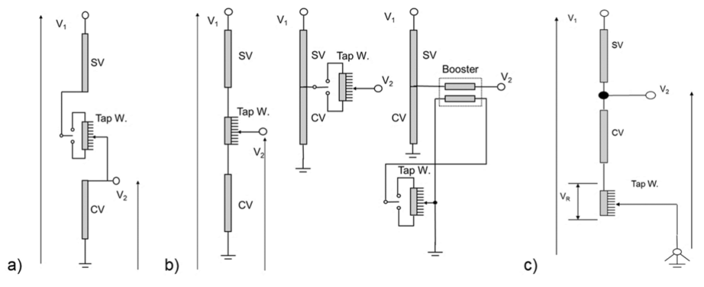
For the autotransformers with on-load tap changers the following voltage variation schemes are used (see Fig.2):
• voltage variation in HV circuit (Fig.2a),
• voltage variation in LV circuit: potentiometer style, forked auto or indirect variation with a booster (Fig.2b),
• voltage variation in neutral (Fig.2c).
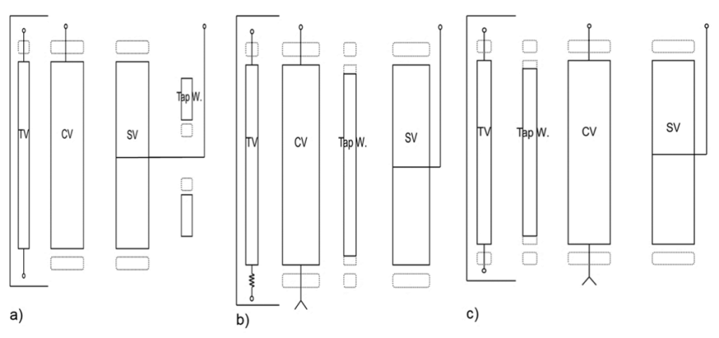
These voltage variation schemes are realized with different winding arrangements shown in Fig.3. Depending on the performance characteristics – impedance swing, the test and operation voltages, number of circuits and impedance between them – a number of winding arrangements is available to achieve optimal performance. In Figure 3 selected three-circuit layouts are presented. These layouts would be similar for two-circuit units, just without a TV winding.
Placement of LTC winding will have influence on the magnetic field distribution, the impedance between circuit, impedance swing, and transient voltage distribution.
A good discussion on tap windings in autotransformers is given in [4]. Here are a few key points from this work related to DTC and LTC taps and their impact on the core flux density and output voltage, as an autotransformer’s output voltage changes, depending on the input voltage fluctuations and/or on the changes in regulation (voltage drop) due to the load variations. The function of the LTC taps is to keep the output voltage constant at all times by compensating for these fluctuations. It is a normal practice to specify LTC taps either on HV side (in series winding) or on LV side (in common winding or in LV line).
1. DTC taps
DTC taps are generally located in the HV (series winding). The DTC tap position is set prior to energizing the autotransformer. During operation of the autotransformer, the DTC taps will neither compensate for fluctuations of the HV system voltage nor will they compensate for regulation due to load fluctuations. This is the main reason to extend the LTC tap range and not to specify the DTC taps.
2. LTC taps in series winding
(a) Step-down operation
When LTC is varied to compensate for input voltage fluctuations then the taps will act as constant flux taps. When LTC is varied to compensate for regulation due to fluctuations in load then the taps will act as variable flux taps.
(b) Step-up operation
When LTC is varied to compensate for regulation due to fluctuations in load then the taps will act as constant flux taps. When LTC is varied to compensate for fluctuations in input voltage then the taps will act as variable flux taps.
3. LTC in common winding (neutral)
Either for step-down operation or for step-up operation and also either to compensate for input voltage fluctuations or to compensate for regulation due to fluctuations in load, the taps will act as variable flux taps.
4. LTC in LV line
(a) Step-down operation
When LTC is varied to compensate for regulation due to fluctuations in load then the taps will act as constant flux taps. When LTC is varied to compensate for fluctuations in input voltage then the taps will act as variable flux taps.
(b) step-down operation
When LTC is varied to compensate for regulation due to fluctuations in load then the taps will act as constant flux taps. When LTC is varied to compensate for fluctuations in input voltage then the taps will act as variable flux taps. When the variable flux is occurring, the transformer core may be driven close or into the saturation and the magnetizing current and corresponding reactive power will increase significantly.
Magnetic field distributions and impedance swing
The basic magnetic field distribution in a two-winding transformer compared to that of an autotransformer is shown in Figure 4.
Depending on location of the tap winding – in LV or HV circuit – and the power flow, i.e. step-up or step-down operation, the distributions of stray flux will be different. For LTC placed in HV circuit, the highest stray flux is generated for all LTC taps in circuit (full raise), while for LTC in LV circuit the stray flux is the highest at lowest tap position (full buck)
The stray flux distribution diagrams can be prepared for all possible winding arrangements. In engineering practice this is routinely done for every design using computer programs calculating the exact field distribution using analytical methods (e.g. Rabin’s procedure to solve Bessel’s equations) or numerical field solvers (e.g. FEM).
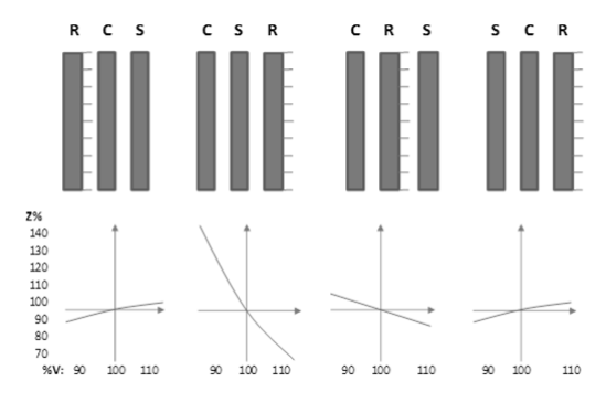
Position of the LTC winding in the circuit and in the geometry of an autotransformer will lead to different impedance values at different tap positions. As example some possible impedance swings, i.e. dependence of impedance on the voltage are shown in Figure 5.
High voltage problems
As the autotransformers are typically connected to two high voltage networks, both HV and LV terminals of the unit will experience high values of operational and transient voltages. The stresses developing inside the autotransformer depend on many factors, such as terminal voltages, the winding geometry, the HV lead connection, grounding of the unit and a system, etc.
Schematically, the designer is analyzing the autotransformer winding through the system on internal capacitances and inductances (see Fig. 6 for examples of the capacitance systems).
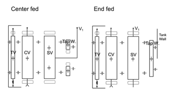
Comparing the way of routing the HV line lead, i.e. the end fed design and the center fed design (Fig.6) one may state that a center fed design reduces significantly the stresses in the winding end insulation. Also, the highest stress will occur in the center of the height between SV and CV windings, in concentric insulation system, which is favourable when compared to that in the end insulation.
In order to study the development of transient stresses inside the autotransformer in details, the complex LCR network needs to be analyzed – this is typically done by using a specialized transient voltage program, e.g. [7, 8, 9]. Firstly, the winding geometry needs to be converted into the system of nodes with LCR components placed between the nodes, corresponding to series capacitances within windings and the parallel capacitances between windings and between windings and grounded parts (tank, core) – see Figure 7. Such a system of nodes is then connected to the voltage or current source, with remaining terminals connected to each other, grounded or floating, depending on the actual connections. With this model the time dependent oscillatory voltages may be calculated for any pair of nodes. As example, see Figure 8 the voltage developing between the TV winding and the core shield while the LI FW voltage of 900 kV is applied to LV terminal.
The industry accepted withstand curves – so called Weidmann curves – are based on the ac applied voltage withstand. The transient voltage needs to be converted then to an equivalent ac voltage. This is well known problem, solved in many ways, e.g. by using corresponding BIL levels based on laboratory research, e.g. [10], or through numerical integration of the waveshapes. After converting the transient voltages to the equivalent ac voltages, the field stress analysis is performed using a harmonic field solver (using FEM, BEM, or similar method), e.g. [11]. In the electric field the designer needs to identify critical stresses as follows:
(i) highest point stress at insulated or noninsulated electrode,
(ii) highest strike in oil gap along selected critical lines, i.e. magnitude of the field intensity as a function of a gap length, Em(x),
(iii) highest creep stresses, i.e. tangential component of the field, Et(x). Next, these stresses are compared to the design limits: the maximum value for the point stress and next, the Em and Et stress curves after averaging procedure are compared to the Weidmann strike and creep criteria curves [11, 12]. As the autotransformers have a complex geometry of windings when compared to that of the power transformer or a GSU, this analysis needs to be repeated for all terminal excitations at all tap combinations.
Transient voltage control
The excessive transient voltages entering the autotransformers need to be controlled to prevent the failure of winding, tap changer or internal/external transformer insulation.
The winding stresses are controlled by using different winding types with different methods of controlling the series capacitance, e.g. interleaved, counter-shielded or with electrostatic shields. The electrostatic shields may be grounded (if placed at the core, or TV winding) or connected to the LV line.
Very effective in reducing transient overvoltages are internal varistors (ZnO disks) – these devices are active only during LI-type transients (i.e. they do not operate during switching surges) as they reduce the transient voltage to low level, protecting LTC or tap winding.
Operational overvoltages in autotransformers
Numerous dangerous overvoltages may appear in the autotransformers, primarily caused by: (i) single line-tog-round (SLG) faults, (ii) specific characteristics of third-harmonic type problems, and (iii) system transients [3]. The overall effect of these causes is heavily dependent on the transformer and system grounding methods, if any. Here, four combinations of the transformer and system’s neutrals grounded and/or isolated are briefly discussed and summarized in Table I.
In case of autotransformers, the system transients (lightning strokes, switching transients or rapid SLG faults) impinging on the HV terminals will concentrate mostly within the SV winding and through inductive and capacitive coupling transfer to CV winding, inducing high potentials in this winding. If the transformer neutral is not grounded these overvoltages in CV winding will occur as the voltage between the transformer neutral and the ground, often exceeding the rating of the neutral, called transient inversion.
Table 1. Classification of operational overvoltages in autotransformers
Notes and explanations:
A – satisfactory conditions
B – moderately safe conditions
C – dangerous conditions
1ph – single-phase autotransformer
3ph – three-phase autotransformer with three-legged core
TV – autotransformer with delta-connected tertiary winding (more details in [3])
1. Transformer neutral grounded, system neutral grounded
This is the optimal condition for a transformer operation, safe under low-frequency transients even for the single-phase units. SLG fault on the primary side will short-circuit the generator and cause the collapse of the voltage at the transformer, but no short circuit current will flow through the transformer. Third-harmonic voltages are reduced to negligible values, because third-harmonic currents can flow through lines and generators and return through the ground.
2. Transformer neutral isolated, system neutral isolated
This is typically a satisfactory condition for SLG faults, however the transient inversion may develop in the neutral. Single-phase units should be equipped with a TV winding and three-phase units may be protected with the surge arrestors (between the neutral and ground) against transient inversion.
3. Transformer neutral isolated, system neutral grounded
Transient inversion is highly probable, similarly as in case 2 above and needs to be taken into account. The SLG fault on one of HV lines will elevate the voltage to ground on the LV windings of unfaulted lines due to trip of zero potential from isolated neutral to grounded HV line.
4. Transformer neutral grounded, system neutral isolated
The single-phase units without TV windings a susceptible to third-harmonic phenomena and should be avoided. Three-phase core-type units and single-phase units with TV winding can operate safely in this condition. For all autotransformers without TV winding (except three-phase, three-legged units), high third-harmonic voltages may be induced by a resonance between the third-harmonic magnetizing reactance of a transformer and a capacitance of transmission line. Therefore, a delta-connected TV winding is necessary to circulate the required third-harmonic magnetizing current and prevent the resonance.
REFERENCES
[1] Mini, J. et al “Performance of Auto Transformers with Tertiaries Under Short-Circuit Conditions”, AIEE Trans., 1923
[2] Farry, O.T. “Autotransformers for Power Systems”, AIEE Trans., 1954
[3] Blume, L.F. et al, “Transformer Engineering – A treatise on the theory, operation, and Application of Transformers”, John Wiley & Sons, Inc, New York, 1951
[4] Kalicki, T. and Sankar, V. “Taps in autotransformers” – presentation given during IEEE Transformers Committee meeting in Toronto, Canada, Oct. 25, 2010 available on Transformers Committee website: http://www.transformerscommittee.org/
[5] Alexander, G.W., McNutt, W.J. “EHV Application of Autotransformers”, IEEE Trans.on PAS, 1967
[6] Wilson, W. “Phase-Phase Switching Surges on 500-kV Transformer-Terminated Lines, Part II: Switching from LowVoltage Terminals”, IEEE Trans. PAS , 1970
[7] Degeneff, R.C. “A General Method For Determining Resonances In Transformer Windings”, IEEE Trans. PAS, 1977
[8] Seitlinger, W.P. et al “ Investigations of an EHV autotransformer tested with open and arrester terminated terminals”, IEEE Trans. Power Delivery, Vol. 11, No. 1, January 1996
[9] “Electrical Transient Interaction between Transformers and the Power System”, Cigre Technical Brochure 577, 2014
[10] Okabe, S., Takami, J. “Evaluation of Breakdown Characteristics of Oil-immersed Transformers under Nonstandard Lightning Impulse Waveforms – Method for Converting Non-standard Lightning Impulse Waveforms into Standard Lightning Impulse Waveforms”, IEEE Trans. DEI, 2008
[11] Ziomek, W., Vijayan, K., Boyd, D., Kuby, K., Franchek, M., “High Voltage Power Transformer Insulation Design”, IEEE Electrical Insulation Conference Record, Annapolis, MD, USA, 2011
[12] Ziomek, W “Autotransformers”, Doble Life of a Transformer seminar, 2015
Author: Dr. Waldemar Ziomek, PTI Manitoba Inc., 101 Rockman St., Winnipeg, MB, R3T 0L7, Canada. Email: wziomek@partnertechnologies.net
Source & Publisher Item Identifier: PRZEGLĄD ELEKTROTECHNICZNY, ISSN 0033-2097, R. 94 NR 10/2018. doi:10.15199/48.2018.10.02
