Published by Michał KONARSKI, Paweł WĘGIEREK, Lublin University of Technology, Faculty of Electrical Engineering and Computer Science, Lublin, Poland
Abstract. The article presents assumptions, characteristics and conclusions of functional tests of a pilot implementation of a power restoration system in one of the Distribution System Operators. The main objective of conducted and described tests was to verify scenarios realized by the automation system during the real and controlled short-circuit tests inside a medium voltage overhead distribution grid. The tests were carried out using a remotely controlled circuit breaker that was used to simulate single phase ground faults at various points of a analyzed grid.
Streszczenie. W artykule przedstawiono założenia, charakterystykę i wnioski z prób funkcjonalnych pilotażowego wdrożenia systemu odbudowy zasilania na terenie jednego z Operatorów Systemu Dystrybucyjnego. Głównym celem przeprowadzonych i opisanych prób była weryfikacja realizowanych przez automatykę scenariuszy podczas rzeczywistych, kontrolowanych prób zwarciowych w głębi napowietrznej sieci średniego napięcia. Próby przeprowadzone zostały przy użyciu zdalnie sterowanego wyłącznika, za pomocą którego zasymulowano jednofazowe zwarcia doziemne w różnych punktach objętej wdrożeniem sieci. (Wykorzystanie systemów odbudowy zasilania w procesie automatyzacji pracy sieci dystrybucyjnej średniego napięcia)
Keywords: smart grid, grid automation, power system restoration, FDIR.
Słowa kluczowe: sieć inteligenta, automatyzacja pracy sieci, systemy odbudowy zasilania, FDIR.
Introduction
Growing quality and continuity requirements of energy customers and a quality regulation model introduced by the Energy Regulatory Office require from the Distribution System Operators (DSOs) to constantly develop their grids to improve the power supply reliability. The new model of regulation was introduced to reduce the values of reliability indices in Poland which, despite increased investments, still significantly deviate from the European average. The quality regulation model assumes that the following indicators will have a direct impact on the DSOs regulated revenue:
• SAIDI – System Average Interruption Duration Index, covering faults over 3 minutes, measured in minutes per customer,
• SAIFI – System Average Interruption Frequency Index, covering faults over 3 minutes, measured in the number of breaks per customer,
• Time of realization of customer grid connection, measured in calendar days per connected customer,
• Time of measurement and billing data transmission, measured in calendar days per customer
The SAIDI and SAIFI indices are the most important indicators for managing existing power grid infrastructure. Achieving the requirements in this field also seems to be the biggest challenge of the new regulation model. According to the quality regulation, the distribution companies are required to reduce SAIDI and SAIFI by 50% to year 2020, at the base year 2015 [1,2]. An important factor affecting fault duration is the time necessary for fault detection and appropriate grid reconfiguration. After the occurrence of grid disturbance (short-circuit or earth fault) it is generally possible to make an appropriate switching, resulting in the maximum reduction of the number of consumers without power supply. Properly fast actions in this area have a direct impact on SAIDI – by maximum reduction of fault duration for customers who can be supplied by grid reconfiguration, as well as SAIFI – by reducing fault duration for these customers below 3 minutes thus it is not included in the index value. These activities have been realized so far by the dispatching service which, especially in extensive failures cases, required each time a long-term analysis and numerous switching, often executed manually by the electricity emergency service. Investment programs carried out in recent years, related to remotely controlled switches implementation and equipping them with protections relays and fault indicators, enabled to use them for a completely new task – a distribution grid automation in disturbance states through the use of power restoration systems called FDIR (Fault Detection, Isolation and Restoration), recognized as one of the most important components of the Smart Grid [3]. The significance of activities in the medium voltage grid is underlined by the fact that it is currently the main source (about 75-80%) of all unplanned interruptions, which makes it the main area for improving reliability of power supply [4].
Medium voltage distribution grid automation
Automation and monitoring have been recognized as key elements of the Smart Grid concept in the medium voltage (MV) distribution grid. The idea of grid automation involves remote control and monitoring to selected switches inside the MV grid and automating the processes previously performed by dispatchers and the electricity emergency service. Activities taken in this aspect are aimed at implementation or supporting following processes and functions [5]:
• switching automation,
• safe use of existing power grid infrastructure during normal and fault conditions,
• grid development planning,
• optimal power-flow calculation,
• power grid losses optimization,
• short-circuit power calculation,
• voltage regulation,
• optimization of sectional switches locations,
• selection of connection points for additional energy sources
One of the main objectives of intelligent distribution grid implementation is to improve reliability of power supply for electricity consumers. The key element of power reliability is switching automation combined with faults detection and localization. The implementation of automation idea requires a common installation of remotely controlled switches with short-circuit and earth fault detection and equipping them with a reliable communication system with a dispatch center. The ability to quickly grid reconfiguration and isolation of its damaged part has been recognized as the key functionality of an intelligent MV grid. The significance of the discussed issue was also noticed by distribution companies which in investment strategies place special emphasis on MV automation process.
Isolation of a damaged grid part can be realized by area control (from MV substation level), local automation (reclosers) or central remote control from SCADA level. The central control enables the use of more complex switching algorithms and gives the dispatcher greater possibilities of quick intervention. The disadvantage of central control is the need to use an extensive communication system and its sensitivity to transmission quality and various errors. The implementation of a smart distribution grid is possible only by the use of a central monitoring and control system, enabling complex control and data analysis functions.
The main purpose of central-level remote control is to isolate the damaged part of the grid and ensure electricity to the largest possible number of consumers. There are three levels of automation that accomplish this task [5]:
• Level 1 – manual control by the dispatcher;
• Level 2 – control by the dispatcher with the switching sequence proposal;
• Level 3 – full automatic control and switching (without human intervention).
All mentioned control levels assume short-circuit detection systems in remote controlled switches and the use of obtained information in isolation process. The first level assumes that switching decision are made by the dispatcher on the basis of measurement system information (load current values and shot-circuit current flow) as well as his own knowledge about the grid. The second level essentially means a complete switching automation system, devoid of a control feedback only. When the system detects fault in a MV grid, a switch sequence proposal is generated, but the decision which switching will be made, still remains dispatcher’s responsibility. The third level of automation, in which switching operations are performed automatically without dispatcher’s participation (through a dedicated SCADA module), ensures maximum improvement of power reliability indices and should be finally implemented in the dispatching system.
A complete and reliable system of automatic isolation should have the following characteristics [5]:
• Autonomy – automation system, after detecting fault in the MV power line, will issue an appropriate warning for the dispatcher and perform switching operations, restoring power to the maximum possible number of recipients, and then will generate a report for the dispatcher;
• Safety – automation system cannot perform switching that will endanger people’s life and health (e.g. electricity emergency services working on power grid electrical devices);
• Adaptability – any change in grid configuration (such as switching execution on the dispatcher’s command or as a result of protection relays operation) automatically adjusts the automation system to the new conditions. Lack of communication with object devices also causes a change of system configuration;
• Scalability – the ability to expand the system, i.e. adding more modules and devices as well as implementing automation system in new areas of the grid.
The scope of information necessary for correct operation of such automation system includes [5]:
• information about a ground fault or phase-to-phase fault occurrence – the source of this data are fault indicators installed in switching points and measuring systems equipped with fault detection algorithm,
• MV switches status (open, closed, blocked or earthed),
• state of communication with remotely controlled switches,
• disengaging of remote control in switch actuator,
• actual and maximum load current of particular power lines,
• information about works carried out on power grid electrical devices. This information should be obtained in general from the dispatching system as well as other cooperating systems.
Power restoration systems
In response to the presented requirements and growing demand for automation solutions, the leading SCADA suppliers offered DSOs a completely new product – Fault Detection, Isolation and Restoration (FDIR) systems. These systems enable a completely autonomous reconfiguration of a power grid after a fault, maximally limiting the range and duration of power supply interruptions.
A FDIR power restoration system realized its functionalities in the following steps:
1) Fault Detection (FD) based on information about shortcircuit current flow obtained from protection relays and fault indicators,
2) Isolation (I) of damaged power grid sections by switching them off using remotely controlled switches,
3) Restoration (R) of power supply to the largest possible number of recipients by power grid reconfiguration.
All presented steps should be realized in less than 3 minutes – the range of long or very long break is minimized, which results in effective reduction of SAIDI and SAIFI reliability indices.
FDIR works through close cooperation of switches actuators, protection relays and other power grid devices, communicated with a SCADA dispatching system. The power restoration module is an IT tool, integrated with SCADA. To properly integrate power grid devices with FDIR automation and ensure its effectiveness, the following conditions must be met:
• Installation of an appropriate number of remotely controlled switches inside the MV distribution power grid. Depending on the needs, it can be reclosers with protection relays, load break switches (with or without sectionalizer function) and indoor substations with short-circuit indicators.
• Correct calculation of relays and indicators settings and its correct gradation with digital protections in substations.
• Reliable and preferably redundant communication system between SCADA and power grid devices. The bilateral data and commands should be sent quickly and confidently within several seconds.
For proper operation of the automation algorithm it is necessary to obtain certain, reliable and consistent information from fault indicators in load breakers and protection relays in reclosers and substations. Special requirements apply to the fault indicators – they should meet the following conditions:
• realized at least current measurements (3xI0) – for insulated and resistor-earthed power grids,
• realized both current and voltage measurements (3xI0, 3xU0) – recommended for a compensated grid,
• enable separate detection and signalization of earth and phase-to-phase faults,
• have an appropriately wide and precise range of settings (especially for earth faults),
• have a built-in disturbance recorder, available remotely via a high-speed engineering link to analyze indications and activations.
It should be noted that these assumptions do not meet electromagnetic field indicators – their indications reliability is at only 50-60% which is definitely not enough for FDIR needs. In the case of incorrect fault indication or incorrect automatic operation, FDIR will incorrectly calculate fault area and control sequence for power grid reconfiguration. Due to inconsistent information about short-circuit current flow, errors in switching devices (such as switch position error, low gas pressure, battery discharge or communication error) or because of local or remote blockades, the automation stops its operation. The use of advanced logic functions and algorithms, that supervise the correctness of location, isolation and restoration of a power supply, ensures high system security. In order to ensure the safety of people and devices during operation, FDIR takes into account a number of information received from SCADA, such as ongoing grid works, installed earthing systems, split bridging and damages, preventing dangerous switching operations.
Currently, there are two different approaches to the implementation of FDIR power restoration systems – the first one, based on previously developed and approved scenarios, and the second, in which the control sequences are each time calculated by the system algorithm for an actual grid topology and parameters. Both methods are characterized by different advantages and disadvantages and the choice of the optimal solution depends on grid characteristic and individual requirements and preferences of the power system operator. However, both solutions enable fully autonomous system operation, both response to the requirements of a smart distribution grid and both may contribute to the reduction of SAIDI and SAIFI reliability indices. In the Polish distribution system, the leaders in pilot implementations of both FDIR types are Mikronika with the FDIR module dedicated to its SYNDIS RV SCADA and Apator Elkomtech with the FDIR system designed to work with its WindEx SCADA [6,7,8,9].
Assumptions and characteristics of implemented FDIR automation
Described in the article pilot implementation of the FDIR power restoration system covers 6 overhead medium voltage lines supplied from two sources – 5 lines from a HV/MV substation and 1 line from a MV/MV substation. The automation system consist of a total of 13 single and multi-switch points inside the MV overhead distribution grid. The implemented FDIR system includes:
• substations circuit breakers with protection relays,
• recloser with protection relay,
• load break switches with fault indicators,
• load break switches without fault indicators,
• sectional load break switches.
The topology of the analyzed MV overhead power grid is shown in Figure 1.

The described FDIR automation operates on the basis of previously developed and approved scenarios, which starts after a fault occurrence and activation of a protection relay in a substation supply field. A SCADA implemented algorithm should automatically:
• Locate the fault,
• Isolate a damaged line section from the supply side in off-load conditions,
• Isolate a damaged line section from the other sides,
• Restore power to non-damaged line sections from others lines, most often using sectional switches.
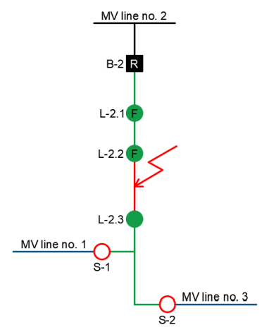
The stage of scenarios creating allows to exact verification of system operating and switching possibilities. Depending on the existing grid infrastructure, it is also possible to realize alternative scenarios. A selected automation scenario checked during functional tests is presented below. The scenario covered FDIR operation in the MV line no. 2 area, and a fault occurs between switches L-2.2 and L-2.3. The normal grid operation was assumed – line supplying from the B-2 line bay in the HV/MV substation and opened both sectional switches S-1 and S-2. The grid topology and the assumed fault location are shown in Figure 2.
The first automation step is to find the fault location. It is possible through activation of fault indicators at the L-2.1 and L-2.2 switches. On the basis of the information from indicators, FDIR locates the fault location on the line section behind the L-2.2 load switch. Simultaneously with the fault indicators, the protection relay in the B-2 line bay is activated and, after the set time, the circuit breaker is turned off. All recipients supplied from the line no. 2 are deprived of power supply. The grid status after switching off the circuit breaker is shown in Figure 3.

The next automation step is the isolation of the fault location. Due to the lack of a fault indicator in the L-2.3 load break switch, FDIR is unable to clearly determine where the fault occurred – on the line section between the L-2.2 and L-2.3 switches or behind the L-2.3 switch. In this situation, the only possibility of more precise fault location is to open the L-2.3 load switch in off-load conditions, and then to switch on the line to the test (Fig. 4).

Due to a fault location between the L-2.2 and L-2.3 switches, the opening of the L-2.3 load switch does not isolate the fault and line switching on causes a repeated short-circuit current flow. The fault indicators and the substation protection relay are activated again. Again, after the set time, the line is switched off by the B-2 circuit breaker. Despite the fault is not isolate, the test line switching on clearly defined the fault location between the L-2.2 and L-2.3 switches. Thanks to this, FDIR can properly isolate the fault by opening the L-2.2 load switch. The damaged line section is isolated from both sides (Fig. 5).

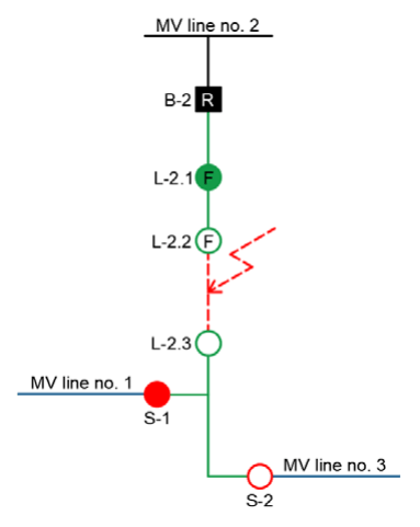
The last automation step is to restore power to the largest possible number of recipients. In the assumed scenario, this happens in two stages. In the first one, by switching on the B-2 circuit breaker, the power is restored to the recipients connected to the line no. 2 between the substation and the L-2.2 load switch. In the second one, by closing the S-1 sectional switch (or S-2 in the alternative scenario), the power supply is restored to the recipients connected to line no. 2 behind the L-2.3 load switch. These recipients are powered respectively from the line no. 1 (in the basic scenario) or from line no. 3 (in the alternative scenario). The restoration of power supply is the last step of system operation, followed by automation blocking on the analyzed line. The effect of FDIR operation is reduction of the failure effects only to the grid section between the L-2.2 and L-2.3 switches (Fig. 6). For recipients connected to other grid sections, the power is automatically restored in less than 3 minutes, significantly reducing the impact of the failure on the SAIDI and SAIFI indices.
Functional tests of FDIR automation
The main objective of FDIR automation functional tests was to check the proper automation operation and, in particular, realization of relevant, approved scenarios. Functional tests were preceded by a comprehensive check of remote controlled switches. The check purpose was to ensure reliable operation of switches, protection relays and fault indicators, stable radio communication channel and proper cooperation of all system components. The check included:
• Radio communication level,
• Proper functioning of the switch (with remote maneuvers),
• Settings of fault indicators and protection relays,
• Activations of indicators and relays operations in case of short-circuit and earth fault in individual phases.
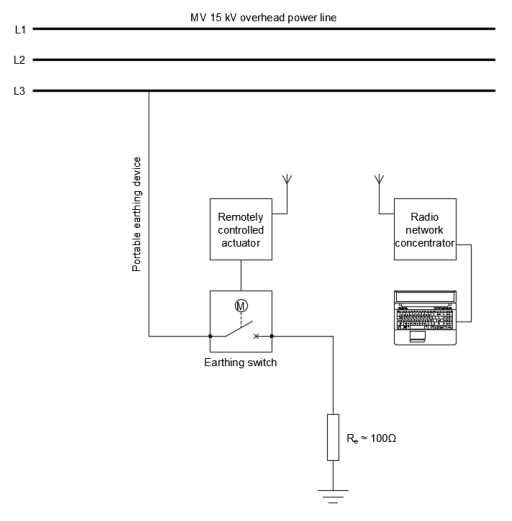
Conducting a comprehensive check of switching points made possible to properly prepare the grid to carry out the real functional tests, checking the automation operation with the assumed scenarios. During testing, the MV grid covered by the automation operated in the normal conditions. In order to simulate the fault conditions, triggering automation operation, controlled single-phase earth faults were made at selected grid points using a grounding switch. As a grounding switch it was used a small oil volume circuit breaker, enabling switching on and off short-circuit currents. The connection of the earthing switch to an overhead MV line was made by a portable earthing device, which was mounted directly from the ground. The grounding of the second circuit breaker terminal was made by connected copper grounding rods. The target value of earthing resistance during short-circuit tests has been set at 100 Ω. In order to ensure the safety of the earthing switch staff, the switch has been equipped with a remote control actuator. For this purpose, a dedicated, PC-connected radio communication data concentrator was used. The scheme of the earthing switch stand is shown in Figure 7.
Short-circuit tests were carried out in the following steps:
1) Preparation for testing by switching off the MV overhead line section and opening the low voltage switch in the transformer station.
2) Connection of the earthing switch in load-free state (in open position) to one of the phases of the disconnected MV line and realization of functional earthing of the earthing switch second terminal.
3) Switching on the MV overhead line section – voltage is providing to the open earthing switch.
4) Switching on the earthing switch on earth fault – short-circuit current flows and the FDIR automation starts working.
5) Verifying the correctness of the switching made by FDIR – the system realizes automatic fault isolation in load-free state and automatic power restoration for undamaged line section according to the scenario.
6) After isolation of the earthed line: opening the earthing switch, removing the portable earthing device as well as functional earthing, switching on the isolated line section, closing the low voltage switch in the transformer station.
The presented functional tests were performed for each of the grid areas covered by the FDIR automation (6 locations), allowing checking the correctness of scenarios realization. Although the functional tests were preceded by simulations and devices checking, during the trials there were abnormalities in the system operation, related mainly to inadequate settings of relays and indicators aa well as with too long information flow time between actuators and SCADA. After eliminating the abnormalities sources, shortcircuit tests were carried out again, this time with a fully positive result – for each of the grid areas, the automation worked properly, according to the assumed scenarios. During the functional tests, total fault detection, isolation and reconfiguration times were achieved below the required 3 minutes, so the interruptions for customers connected to the undamaged line section were not included in SAIDI and SAIFI reliability indices, thus meeting the main objective of the described implementation.
Conclusions
1) The quality regulation model introduced by the Energy Regulatory Office require Distribution System Operators to significantly reduce the SAIDI and SAIFI reliability indices (by 50% by 2020).
2) The main area to improve the power supply reliability is a medium voltage distribution grid, which currently is the main source (about 75-80%) of all unplanned interruptions.
3) The key factor affecting the length of power supply interruptions is a time needed for fault location and adequate grid reconfiguration.
4) Reducing the time to restore power in undamaged grid sections below 3 minutes allows the maximum reduction of SAIDI and SAIFI indices.
5) These requirements are met by the FDIR power restoration systems which enable fully autonomous fault location, isolation of damaged grid sections and grid reconfiguration in order to restore power to the largest possible number of recipients.
6) The conditions for effective automation are the installation of a sufficiently high number of remotely controlled switches inside the MV grid, correct determination and adjustment of settings of protection relays and fault indicators as well as reliable communication system with SCADA.
7) The algorithm of the implemented FDIR system uses previously agreed and verified scenarios, which allows accurate planning of automation operating.
8) The implementation of the FDIR automation in the analyzed grid was successfully completed – during the functional tests, for each area, the automation system realized the assumed scenarios.
9) Short-circuit tests were necessary to verify the correctness of the system operation and to remove abnormalities in the settings of protection relays and fault indicators as well as problems in communication between power grid devices and SCADA.
REFERENCES
[1] Urząd Regulacji Energetyki, Regulacja Jakościowa w latach 2016-2020 dla Operatorów Systemów Dystrybucyjnych, Warszawa, Poland (2015)
[2] Marzecki J., Drab M., Regulacja jakościowa – sposób na poprawę niezawodności sieci dystrybucyjnych, Przegląd Elektrotechniczny, 93 (2017), no. 5, 12-16
[3] Babs A., Automatyzacja sieci rozdzielczych jako podstawowy element sieci inteligentnych, Automatyka – Elektryka – Zakłócenia, 4 (2013), no. 2, 22-28
[4] Kornatka M., Prognozowanie kluczowych wskaźników efektywnościowych w modelu regulacji jakościowej, Przegląd Elektrotechniczny, 93 (2017), no. 3, 48-51
[5] Kubacki S., Świderski J., Tarasiuk M., Kompleksowa automatyzacja i monitorowanie sieci SN kluczowym elementem poprawy niezawodności i ciągłości dostaw energii, Acta Energetica, 10 (2012), no. 1, 57-63
[6] Apator Elekomtech SA, FDIR – System odbudowy zasilania SN, Available at: http://www.elkomtech.com.pl, accessed on 03 April 2018
[7] Mikronika SA, FDIR – moduł programowy w systemie DMS SCADA SYNDIS RV, Available at: http://www.mikronika.pl, accessed on 03 April 2018
[8] Mikronika SA, Systemy zdalnego nadzoru od Mikroniki, Urządzenia dla Energetyki, (2016), no. 8, 2-6
[9] Kalusiński K., Karbowski J., Systemy odbudowy zasilania w sieciach dystrybucyjnych SN, proceedings of Konferencja Technologie w Energetyce, 27-29 April 2016, 26-35
Authors: dr hab. inż. Paweł Węgierek, prof. PL, mgr inż. Michał Konarski, Lublin University of Technology, Department of Electrical Devices and High Voltages Technologies, Nadbystrzycka 38A, 20-618 Lublin, Poland, E-mail: p.wegierek@pollub.pl, m.konarski@pollub.pl
Source & Publisher Item Identifier: PRZEGLĄD ELEKTROTECHNICZNY, ISSN 0033-2097, R. 94 NR 7/2018. doi:10.15199/48.2018.07.42
