Published by Electrotek Concepts, Inc., PQSoft Case Study: PQ Investigation for SW County School District No. 1, Document ID: PQS0323, Date: October 10, 2003.
Abstract: The County School District has a concern for increasing computer loads at the local High School. There are approximately 300 computers currently in use at the school and plans are to increase the number of computers significantly over the next 3-4 years. The existing computer loads are on the same circuits with lighting loads, other office loads, and building HVAC loads.
Electrotek Concepts conducted a brief survey of the facility on August 8, 1995. This case study describes the findings from the site survey and outlines recommended procedures for dealing with the new computer loads.
INTRODUCTION
The County School District has a concern for increasing computer loads at the local High School. There are approximately 300 computers currently in use at the school and plans are to increase the number of computers significantly over the next 3-4 years. The existing computer loads are on the same circuits with lighting loads, other office loads, and building HVAC loads.
The personal computer loads are characterized by a current waveform that has significant harmonic components. These harmonic components are dominated by the third harmonic which appears in the zero sequence circuit (for balanced circuits), which means that the third harmonic components add in the neutral. The result can be neutral circuits which are significantly overloaded if they are not designed for this type of load. The harmonic components can also require derating of the transformers that supply the computer load.
Wiring and grounding considerations are also important with the computer loads. High neutral currents from the PC loads can also flow in the ground circuits if there are incorrect neutral-ground bonds in any sub-panels or loads. The ground currents can cause interference, improper operation of protective devices (breakers), and safety concerns.
System Configuration
The high school is supplied from a 1000 kVA transformer that steps down to 480 Volts. There are a number of transformers that then step down from 480 volts to 120/208 for the various loads in the facility. Figure 1 gives an overview of the system configuration. The 500 kVA transformer supplies most of the load in the main building. The 300 kVA transformer was added for the auditorium load.

Concerns Evaluated
Important concerns evaluated in the site survey and summarized in this report include:
• Harmonic generation from nonlinear loads.
• Overloading of neutral conductors due to harmonic current levels.
• High voltage distortion on the auditorium circuits.
• Transformer derating considerations for harmonic currents
• Wiring and grounding concerns at building panels and loads.
• Requirements for main transformer rating in the future.
HARMONIC GENERATION BY NON-LINEAR LOADS
Harmonic currents result from the operation of nonlinear loads in the system. These include adjustable speed drives for fan motors and chiller compressors in HVAC systems, fluorescent lighting (with or without electronic ballasts), electronic dimmers for lighting, and electronic power supplies for computers and other electronic equipment.
These nonlinear loads look like sources of harmonic currents to the rest of the system. Voltage distortion results as the harmonic currents flow through the impedance of the conductors, transformers, and system. Longer conductor runs will result in higher voltage distortion levels due to the higher impedance of the circuit.
Measurements were performed previously at the high school to characterize some of these loads. Important results are included here for illustration purposes. These include measurements of the harmonic distortion in the stage lighting circuits which use electronic dimmers and measurements of a typical circuit that is dominated by computer loads.
Harmonics from Computer Loads
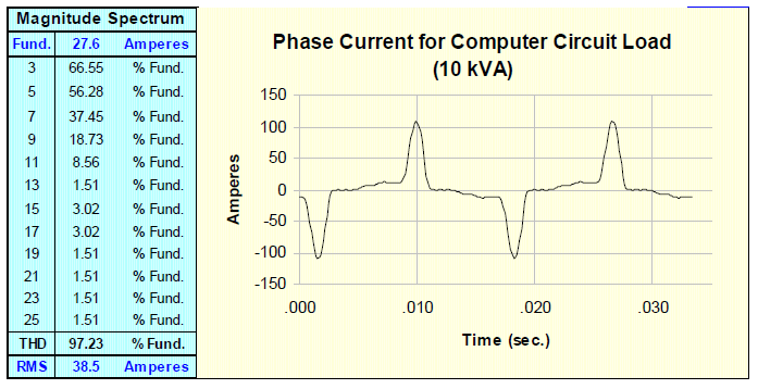
Panel PE is a typical panel that supplies computer loads at the high school. Measurements were performed for the total load at Panel PE. Figure 2 below gives an example of the waveform measured.
A summary of the three phase measurements at Panel PE are provided below in Table 1.
Table 1 – Panel PE Measurement Results
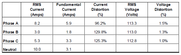
Note that the neutral current is higher than the phase current at this panel. The neutral current would even be higher if the three phase currents were balanced. In the balanced case for load current waveforms like the one in Figure 2, the neutral current can be as high as 173% of the rms phase current. It will be dominated by the third harmonic component since this is the component that adds in the neutral.
Harmonics in the Auditorium Dimmer Circuit
The stage lights for the auditorium in the high school use electronic dimmers which result in significant harmonic generation. The harmonic content of these load currents depends on the actual load level. When the dimmers are near full load, the percentage harmonic component is not as great but the load current magnitude is higher. At light loads, the percentage distortion is high but the load current is lower.
Measurements were performed at three different load levels to illustrate this characteristic. The results are summarized in Table 2 and example waveforms are provided in Figure 3.
Table 2 – Current and Voltage Measurements for the Stage Lighting Circuit


Note that the highest voltage distortion levels for this circuit occur when the lighting is near 50% load. At this operating point, the actual amperes of harmonic current components are the highest. The voltage distortion is high because the circuit supplying the lighting has a high impedance due to the long 120 volt circuit supplying this load. The impedance would be much lower and the distortion would be reduced if the auditorium load was supplied with a 480 volt circuit and the step down transformer was installed closer to the auditorium.
EVALUATING NEUTRAL CONDUCTOR LOADING DUE TO HARMONICS
Single phase nonlinear loads can have significant harmonic components at triplen frequencies (3, 9, 15, etc.). When these loads are combined in a three phase circuit, the triplen harmonics show up as zero sequence components. That means they add in the neutral. If there are 10 amps of third harmonic on each phase in the three phase circuit, the neutral current will include 30 amps of third harmonic.
For this reason, neutral currents in 120/208 circuits in many commercial buildings are actually higher than the phase currents. The neutral currents are dominated by third harmonic components from single phase electronic loads, like Pcs. Figure 4below illustrates a typical case in a circuit dominated by PC loads.

The rms neutral currents in this type of circuit can be as high as 173% of the rms phase current. The actual neutral current magnitude will depend on how much of the load on the circuit has a waveform like the ones in Figure 4.
An approximate formula for calculating the neutral current magnitude as a percentage of the rms phase current is given below. The formula is based on the assumption that the circuit loading is balanced, that the nonlinear load watts are a pnl fraction of the total load, and that the load current has a third harmonic component equal to 70% of the fundamental.
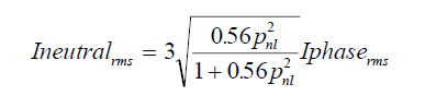
This relationship is illustrated in graphical form in Figure 5.

It is important to note that the neutral current problem is usually restricted to 120/208 volt circuits supplying a significant percentage of single phase electronic load. Neutral currents are very seldom a problem at service entrance locations, due to delta-wye transformers and harmonic cancellation between different types of loads.
The figure shows that the neutral current will be equal to the phase current when approximately 50% of the load on the circuit is electronic loads. For circuits with higher percentages of electronic load, the neutral current will exceed the phase currents. If these circuits are loaded based on the capacity of the phase conductors, the neutral conductor could be overloaded.
Possible solutions to the neutral conductor overloading problem include the following:
− increase the neutral conductor size or use two neutral conductors.
− use a separate neutral for each phase conductor.
− apply a third harmonic filter at individual loads.
− use an isolation transformer, zig-zag transformer, passive filter, or active filter (three phase devices) on the load side of the neutral conductor to be protected.
Implications for SW County High School
With the number of PCs planned and existing at the high school, a number of circuits will be dominated by electronic loads. There is a concern for neutral conductor loading on these circuits. Panel PE and Panel I are examples of panels that supply load that is dominated by PCs.
Most existing circuits do not seem to be loaded close to their rating. In addition, circuits examined have neutral conductors that are the same size as phase conductors (they could be undersized according to the code). As a result, neutral conductors are not being overloaded at the present time. Circuit loading should be reviewed periodically on circuits that are dominated by computer load to assure that neutral conductors are not being overloaded.
New circuits that are installed to supply future PC loads should have neutral conductors that are sized for this type of load. Neutral conductors in new circuits supplying pc loads should have a rating of about twice the phase conductor rating.
TRANSFORMER DERATING REQUIREMENTS
Transformer heating is one of the primary concerns associated with harmonic current distortion levels in a facility. ANSI/IEEE Standard C57 series states that a transformer can only be expected to carry its rated current if the current distortion is less than 5%. If the current distortion exceeds this value, then some amount of derating is required. ANSI/IEEE Standard C57.110 provides calculation procedures that can be used to evaluate the required derating as a function of the expected current harmonic spectrum and the transformer design. The primary cause of the concern is that the transformers can be overheated by distorted load currents that cause higher eddy current losses inside the transformer than were anticipated by the designer.
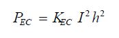
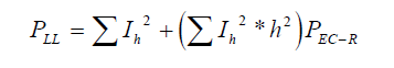
At the inner winding “hot-spot”, the load loss (PLL) can be considered to have two components: I2R loss and eddy current loss (PEC). The relationship is given by:

The I2R loss is directly proportional to the square of the rms value of the current. However, the eddy current loss is proportional to the square of the current and frequency. It is defined by:
where:
KEC = a design-dependent proportionality constant
With all values expressed in per unit of rated load quantities, the per-unit full load loss under harmonic current conditions is given by:
where:
PEC-R = eddy current loss factor under rated conditions
The required transformer derating is calculated based on the additional heating that can be expected for a specific harmonic current spectrum and the eddy current loss factor for the transformer. The derating is expressed as the per unit value of a particular distorted current that will cause the same heating as the rated sinusoidal current.
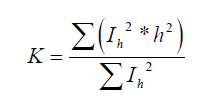
The first task is to measure, calculate, or estimate the harmonic content of the transformer load current. Then, the expected harmonic current spectrum can be used to calculate the k-factor of the load current. The k-factor of the load current can be used to purchase a transformer that is designed to handle the level of harmonic distortion specified. The k-factor is only dependent on the current waveform. There is no need to get any information about the transformer design in order to use the k-factor. K-factor is calculated using the following formula.
The increased transformer losses at harmonic frequencies are caused by increased eddy current losses. If the transformer has very low eddy current losses, there will not be a significant impact due to harmonic components. If the transformer has high eddy current losses, significant derating will be necessary for harmonic components. The transformer eddy current losses are characterized by the eddy current loss factor, PEC-R. This number can be from the transformer designer, from the transformer test data and the procedure in C57.110, or estimated based on typical values. A typical value for dry type transformers used to step down from 480 volts to 120/208 volts within facilities is about 8%.
The transformer derating is expressed as the per unit rms current (with distortion) that will cause the same heating as the rated sinusoidal current. It can be calculated from the following equation using the transformer eddy current loss factor and the k-factor of the load current.

where:
PEC-R = eddy current loss factor
h = harmonic number
Ih = harmonic current
Probably the worst case condition for one of the step down transformers within the facility is virtually 100% electronic load. Figure 6 illustrates the waveform and the required transformer derating for this condition. Note that the k-factor for this waveform is 7.6. A transformer with a k-factor greater than 7.6 could be loaded to its nameplate rating for this load current waveform.
Implications for SW County High School
Both of the step-down transformers (500 kVA and 300 kVA) at the high school main switchgear could have relatively high percentages of nonlinear load. However, the nonlinear load is not approaching 100% of the load on the transformer. Also, these transformers do not appear to be operating near their rating at the present time. A conservative limit for these transformers would be 80% of their nameplate ratings. Loading on the high school step down transformers should be monitored periodically and kept below 80% of the transformer rating to prevent overheating due to harmonic components.
New circuits to supply additional PC loads can be supplied from the main 500 kVA transformer as long as the transformer loading is kept below 80% of the nameplate. If new loads will result in this limit being exceeded, additional transformer capacity should be added. A new transformer to supply electronic loads (PCs) should not be loaded above 60% of its nameplate or a transformer with a k-factor rating of 13 should be purchased.
The main supply transformer for the facility (1000 kVA) should not require any significant derating for harmonic components. The step-down transformers prevent the flow of zero sequence harmonics and there is significant cancellation of harmonics for all the loads within the facility. The main supply transformer should not require significant derating for harmonic levels.
WIRING AND GROUNDING CONSIDERATIONS
Many power quality problems that occur within end user facilities are related to wiring and grounding practices. Sometimes the solution to a power quality problem is simply to tighten a loose connection or replace a corroded conductor. Therefore, an evaluation of wiring and grounding practices is a necessary first step when evaluating power quality problems in general.
Check RMS Voltage Levels
Service entrance should be within +/- 5% of nominal volts. Utilization should be within +6, -13% of nominal volts. The long circuit runs required when the step down transformers are located at the main switchgear can result in reduced voltage magnitudes at the actual loads. Measurements at various panels in the high school show that the voltage can be as low as 110 volts. This should not result in any problems.
Check for extra neutral-ground bonds
There should be only one neutral-to-ground bond per separately derived system (at the transformer or at the main panel). This is a common problem which causes load currents to flow in the building ground system, creating the potential for serious interference problems. This can be checked by measuring the current in the green wire grounds at the service entrance or at the source of the separately derived system. These currents should be very close to zero. If any current is flowing in the ground, the source of the current should be found and corrected.
Visual inspection of a couple sub panels at the high school indicated that the neutral bus in some sub panels may be grounded. Figure 7 below illustrates the possible problem that can be caused by this extra neutral-to-ground connection – some of the neutral return current is introduced into the ground system where it can cause interference.

(caused by an extra neutral-to-ground connection
Check for overloaded neutral conductors
This has already been discussed related to supplying electronic loads with high third harmonic current components. The neutral currents should be measured with a true RMS meter and checked against the ampacity of the neutral conductors.
Checking grounding electrode system
The grounding electrode system consists of all the grounded elements of the building that are bonded together to form a grounding system. This can include ground rods, metal water pipe, building steel, concrete-encased electrodes, a ground ring, etc. All of these things should be bonded together to form the best equipotential reference for equipment in the building as possible.
It is not advisable to have separate, isolated ground rods for individual equipment in the facility. If a separate ground rod is driven for equipment, it should be bonded with the overall building grounding electrode system.
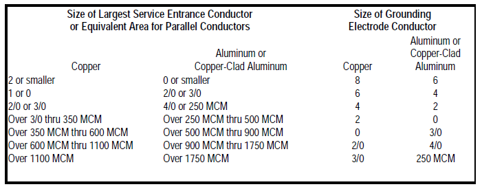
Guidelines for the grounding electrode conductor are provided in Table 3.
Table 3 – Guidelines for the grounding electrode conductor size.
Overall circuit layout considerations
Are sensitive equipment loads on separate circuits from disturbing loads? Loads that are switched or that have power electronic components create transient disturbances which can impact the operation of some sensitive equipment. Loads like switched motors, copiers, laser printers, elevators, etc. should be on separate circuits from sensitive equipment. The separate circuits provide isolation for high frequency transients and a clean ground reference for the sensitive loads.
For new computer loads at the high school, dedicated circuits could be designed with additional neutral capacity to handle the harmonic components.
Separately derived systems
Separately derived systems permit the bonding of the ground and neutral. In circuits with significant neutral currents (e.g. single phase electronic loads), a significant neutral-to-ground voltage will build up if there is a significant length between the loads and the supplying transformer. Using an isolation transformer close to the loads minimizes the neutral-to-ground voltage and also provides isolation for transient overvoltages.
Check for ground loops
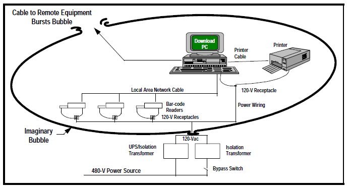
Ground loops are probably the most common cause of interference in network systems and also the most common problems with multi-port devices in general. Multi-port devices have more than one type of interface. For instance, a television has a power input and a cable input; a computer has a power input and a phone input for the modem and a network input for a LAN. All of these ports require a ground reference. This multiple ground reference scenario creates the potential for serious ground loop problems.
Ground loops problems are best avoided by making sure all equipment that is tied together through other ports (e.g. on a LAN) has the same ground reference. This means that all the equipment is part of the same separately derived system. Figure 8 illustrates this as the grounding bubble principle. If an external ground reference goes outside the bubble, there is the potential for ground loop interference.
Implications for Sweetwater County High School
The most important wiring and grounding concern at the high school is extra neutral-to-ground connections at sub panels. Most of the circuits from the main switchgear to the sub panels use conduit grounding. The sub panels should not have the neutral bus connected to the ground bus and case in the panel. This extra connection could result in loss of overcurrent protection for these circuits and interference concerns when PCs are connected up in networks.
New circuits for computer loads should include a separate green wire safety ground conductor. This will facilitate checking for unwanted ground currents in these circuits.
New circuits for computer loads should use a step down transformer as close to the loads as possible. This will prevent excessive neutral-to-ground voltages and long lengths of circuit with high neutral currents that could cause interference.
EVALUATING THE MAIN TRANSFORMER REQUIREMENTS
The addition of new computer load could result in the need for additional transformer capacity in the main supply from the utility. This depends on the existing load levels for the 1000 kVA supply transformer.
The utility performed some measurements at the 480 volt service entrance last year but these were primarily designed to evaluate harmonic distortion levels. Measured levels were compared to the IEEE 519-1992 guidelines and harmonic current levels were not found to be a problem. Some of the plots included with the report appear to be the result of either transient inrush conditions or caused by saturation of Cts (high even harmonic current components should not exist in the steady state). These should not be representative of the normal harmonic current components. As stated in the report, normal harmonic current levels are well within guidelines and should not result in the need for derating of the main transformer.
It would be useful if additional measurements could be performed to characterize the existing transformer loading as a function of time. This would provide a benchmark for evaluation of future transformer capacity requirements.
If the supply transformer is replaced with a larger unit, it should be sized based on the expected future loading at the high school, including the ultimate level of computer penetration.
SUMMARY
General Recommendations
− Harmonic voltage distortion can be high on the auditorium lighting circuits due to the dimmer loads and the high impedance created by the overall circuit length. The voltage distortion could be reduced if the step-down transformer for these circuits was located closer to the loads. Even though the voltage distortion is high, it should not be a problem for the lighting circuits.
− If the voltage distortion on these lighting circuits needs to be reduced, the most economical solution would be a zig-zag transformer applied close to the lighting loads. This would reduce the zero sequence components and the corresponding voltage distortion. The transformer is rated in zero sequence amps. A transformer rated for approximately 250 amps would be needed based on the measurements.
− Existing computer loads are resulting in neutral current magnitudes that exceed the phase currents in some circuits. However, the circuits are not heavily loaded. These circuits should be monitored periodically to make sure that neutral conductor capacities are not exceeded.
− New computer loads can be supplied with dedicated circuits that have a neutral conductor rated for twice the current of the phase conductors.
− Loading of the facility step-down transformers should be monitored periodically. As a conservative limit, they should not be loaded above 80% of their nameplate capacity.
− A new facility step-down transformer dedicated to computer load should have a k-factor of 13 or should only be loaded up to 60% of its nameplate capacity.
− Existing sub panels should be checked for neutral-to-ground connections. The neutral bus in the sub panels should be isolated from the ground bus and the case.
REFERENCES
ANSI/IEEE Standard C57.110
IEEE 519-1992
