Published by Matej KUČERA1, Milan ŠEBOK1, Miroslav GUTTEN1, Daniel KORENČIAK1, Pawel ZUKOWSKI2, Tomasz KOLTUNOWICZ2, University of Zilina, Slovakia (1), Lublin University of Technology, Poland (2)
Abstract. Article presents theoretical and experimental analyses of possible mechanical effect of short-circuit currents on the transformer winding by frequency and time methods. The first part of the paper is focused to mechanical influence of radial and axial forces during short-circuit. These dangerous forces cause mechanical stress in transformer. Above analysis shows that it is necessary to know the size of short-circuit current, because it represents a danger for the operation of transformer. Finally, the article presents experimental methods of diagnostics for analysis of the short-circuit forces on transformer winding by frequency method SFRA and time method – impact test.
Streszczenie. W artykule przedstawiono teoretyczne i eksperymentalne analizy, w dziedzinie czasu i częstotliwości, mechanicznego wpływu prądów zwarciowych na uzwojenie transformatora. Pierwsza część artykułu koncentruje się na mechanicznym oddziaływaniu sił promieniowych i osiowych podczas zwarcia. Te niebezpieczne dla transformatora siły powodują naprężenia mechaniczne. Przedstawiona analiza pokazuje, że konieczna jest znajomość wartości prądu zwarciowego, ponieważ stanowi on zagrożenie dla pracy transformatora. Artykuł przedstawia eksperymentalne metody diagnostyczne, wykorzystywane do analizy wpływu sił zwarciowych na uzwojenia transformatora, wykorzystujące częstotliwościową metodę SFRA i czasową – test udarowy. (Analiza kondycji transformatora za pomocą metod czasowych i częstotliwościowych).
Keywords: short-circuit forces, transformer, diagnostics.
Słowa kluczowe: siły zwarciowe, transformator, diagnostyka.
Introduction
Maintenance diagnostics of transformers considering to the influence of short-circuit currents during the operation should be carried out to increase the reliability in real trouble-free process.
The short-circuits in operation are commonly created by different line faults, etc. in mechanical damage of insulation, an electric insulation, an electric insulation breakdown on over voltage, wrong operation and in the next case row [1].
The short-circuit currents cause a progressive serious disrepair of the transformer, because there are high currents in it which are awfully rising winding temperature, what it can cause damage their insulation. Much more danger is high electro-magnetic forces, which can be the reason for the devastation of transformer.
Considering a significance of power three-phase transformers in the electric system, their price and possible damages arising in accidents, it is necessary to pay attention to higher prevention of these devices. Windings of the transformers should be designed to avoid various mechanical or thermal deteriorations caused by short-circuit currents occurring in operation.
Besides the permanent deformation effects of short-circuit currents, there are also gradual aging process of the electrical device, which can worsen its mechanical properties. Heat shocks can cause decrease of mechanical strength of transformer and consequent unexpected damage of transformer during the operation.
To prevent a damage state of transformers, it is performed different types of the measurements that should illustrate an actual condition of the measured equipment. It is therefore important to choose a suitable diagnostics for the right prediction of such conditions.
The theory of mechanical forces effect on transformer winding during short-circuit
For a better comprehension this relation between transformer damage and short-circuits currents effects, it is needed focused on mechanical forces effect on transformer windings during short-circuit.
The primary cause of the creation of forces, which effect on winding, it is effect of magnetic field on current flowing conductors. As to the transformer it is the field of stray flux. In normal operation, when the currents in transformer create not exceed rating value, in generally the forces affecting on winding are small. But at short-circuits, when the currents reach the multiple of values, the forces can become dangerous for windings or core construction too.
We can divide forces affecting on windings into two groups – radial (cross) and axial (longitude) [2].
Radial forces are a result of lengthwise fields, which are paralleled to axis of transformer winding. These forces are dilating external windings and compressing internal windings, so air spaces are bigger in consequence of it.
The axial forces rise from the center to border of winding, where the magnetic field has the biggest cross component. In short-circuits axial forces can reach dangerous, so they can deform outer coil too [3].
According to [3] it is needed to pay more attention to catching outer coil. In case of released coil, the axial forces Fd can cause displacement of outer coils to the vertical sides. The redundant pressure on spacers can press insulation and moved winding, what can cause seriously damages of transformer.
In Fig. 1 is illustrated pitching of coil conductors by action of the excessive axial forces (effect to insulation compression).

Based on theoretical analysis and model measurements it is needed to create a computing environment short-circuit forces. Based on this diagnostic approach it will be necessary to determine the possible effect adverse phenomenon and the insulation and mechanical state of transformers.
The diagnostic methods and analysis of transformers
The important problem of actual energetic companies is that the data big number of measured parameters from the diagnostic measurements are not adequately further studied. Main technical problem is identification of power transformer condition, mainly in terms of their residual lifetime. The fault may occur in an unpredictable moment of transformer operation. The fault result may be the power breakdown for a short or long time. It is necessary to analyze the measured values of transformer parameters, even for using monitoring. Therefore it is necessary based on knowledge of exposure to adverse influences of energetic phenomena, for example short-circuit currents, overcurrents or overvoltages. Achievements of these objectives by using suitable the diagnostics may help to identification the adverse effects of short-circuit and propose new measuring procedures. Moreover it is possible to identification forthcoming failure into transformer. Some steps are possible to propose in advance (e.g. repair of single parts of transformer) [4].
Considering the adverse effects of short-circuit forces which damage coils, magnetic construction and taps, the following analysis are be realized on disconnect distribution transformers:
• analysis of basic insulation parameters (resistances, permittivity, capacity and loss factor),
• measurement of parameters in time dependence (polarization and depolarization DC currents and return voltages (PDC and RVM method),
•measurement of transformer parameters in frequency dependence by Sweep Frequency Response Analysis method (SFRA),
• analysis of time response of transformer windings by impact test with using the high-voltage impulse source,
• chromatographic analysis of the quality of transformer oils,
• analysis of insulating parameters by frequency dielectric spectroscopy method (FDS),
• measurement of winding parameters of power transformer at short-circuit state,
• measurement of breakdown oil parameters of transformer,
• combination of measuring methods according to the proposed diagnostic procedures.
The use of monitoring diagnostic methods and measurement procedures are useful for connected transformers on electric power. They belong here thermography and noise analysis and monitoring of basic insulating and mechanical parameters of transformers.
Adverse electromagnetic interference from transformer may to cause mechanical change into coil depending on the result of shift or inter-turn short-circuit of the winding.
Therefore it is possible use the following measurements of connected transformers will be realized using experimental apparatuses:
• thermography analysis (Fig. 2),
• analysis of electromagnetic radiation from transformers,
• measurement of acoustic emission from generated at discharges, determination of energy magnitude, speed of exchange between energy of discharge and surrounding oil and localization of faulty state.
The proposed measurements allow us to detect the effects of short-circuit currents and over-currents. These effects can damage winding and magnetic circuit of the transformer. The repair of transformer is costly and time-demanding. Measurement of frequency characteristics by the SFRA method, measurement of time response of windings by the high-voltage impulse source and measurement of parameters of windings at short-circuited state belong to non-invasive diagnostic methods of transformers. There is no need of changing of the construction of the measured machine. Moreover they can be performed at disconnected transformer [5].
Experimental measurement on the distribution transformer
On the basis of theoretical analyses of influences of short-circuits realized in the first phase in the paper and diagnostic methods in the second paper, there were identified single diagnostic and measured methods for measurements on distribution oil transformer 100 kVA.
For identification of mechanical deformation into transformer winding it is possible to use two the most sensitivity methods – response method SFRA and time analysis of transition high-voltage impulse by impact test. It is possible to determine the frequency and time response of characteristic quantities of transformer.
For both diagnostic methods there is no need of intervention into construction of measured equipment, and they are performed at disconnected machine [5].
Analysis of the transformer by frequency method
The diagnostics of power transformers by method SFRA uses for a setting of the frequency range from 20 Hz to 2 MHz at generator voltage 0.2-20 Vpp and output impedance 50 Ω. In our case it was used apparatus Megger FRAX 150. In Fig. 3 is showed connection of the apparatus with measured transformer.
A transformer consists of multiple capacitances, inductances and resistors, a very complex circuit that generates a unique fingerprint or signature when test signals are injected at discrete frequencies and responses are plotted as a curve. Capacitance is affected by the distance between conductors. Movements in the winding will consequently affect capacitances and change the shape of the curve [6].
The diagnostics were performed in condition of no-load and in short-circuit according to international standards. At no-load test is detected a construction state of tested windings, taps and ferromagnetic core of transformer.
The measured curves are visible in low frequencies for problems in core and higher frequencies (from 1 kHz) refer to problems into movement of windings or fault taps regarding to short-circuit forces [7].
At the short-circuit test is detected mainly the winding state in primary or secondary part of transformer. This test notifies reliably of deformation of internal winding and its movement as a result effects of mechanical short-circuit forces.
In Fig. 4 are curves comparison of measurement in no-load and short-circuit of magnitude (dB) and phase (°) for undamaged windings.
Comparing the measurement of attenuation and phase of three windings the same transformer in depending on the frequency in short-circuit test is in Fig. 5.
In Fig. 5 is showed difference between by two coils of the same transformer. Deformation on the coil A is the most sensitive displayed by dependence of the attenuation and phase on the frequency about 1-10 kHz (in lower figure). If the windings of transformer are star connected, different curve between phases B-C means damage of other phase coil, thus coil A.
For calculation method of mathematical analyses of differences between two curves (sequences) is using parameter – relative factor Rxy.
For calculation of two sequences is used normalization factor covariance:
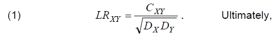
from equation (1) is defined relative factor Rxy [6].
The result of the calculation in short-circuit tests according equation (1) is value for relative factor Rxy=1.17 in the frequency range from 1 kHz to 100 kHz, Rxy=2.07 in the frequency range from 100 kHz to 600 kHz and Rxy=2.43 in the frequency range from 600 kHz to 1 MkHz (Fig. 6), where dominates value of the inductive part which is dependent on the geometry of the coil (at frequency 1 kHz- 100 kHz).
This analyse represents deformation anomaly due to short-circuit in winding, thus damage of the coil A and permanent failure of the transformer (Fig. 6 – visual change of curves from 10-100 kHz and Rxy = 1.17 – suspected distortion).
Time analysis of the transformer
Impact test is often used for analyzing of the insulation between coil threads or themselves of windings and for detection of the attenuated winding sections of transformers. This method enables detecting early states of the winding faults. Short-time voltage pulses are applied to the winding in order to create a voltage gradient across the complete coil of the winding [8].
In the time intervals among pulses the winding react by damping oscillations with sinus form. Each machine winding has unique character of the respond, which could be analyzed by memory oscilloscope [9]. Wave form is influenced by transient circuit dependent on the winding inductance and inside capacity of the pulse generator.
Schematic diagram for the measured method of the impact test on three-winding transformer is in Fig. 7.
In Fig. 8a is showed a comparison of time curves from pulse test measurement on the power transformer, where is possible to note time difference between by two coils. Amplitude decrease is involved by change of the resistance and capacitance of circuit due to damaged winding insulation. The measurement is carried on windings of two phases, where phase A is influenced by short-circuit and phases B and C are without fault.
For determine state of windings it is necessary to understand that single curves to each other overlap when coils are identical and not damaged. Mutually shifted dependents indicate damage on one of the coils; therefore it is handy to analyze time and amplitude differences in curves.
According to Fig. 8a defect can be located in the lower and upper part of the coil A.
Conclusion
In the paper is showed the importance of knowledge about theoretical and experimental analysis of adverse influences, which can result non-reversible deformation or short-turn of the transformer winding. Above analysis shows that it is needed to know the newest methods and procedures of diagnostics of power transformers and know danger for their state.
It is possible to use two methods – frequency SFRA and time impact test for diagnostic transformer windings and to detect a fault on a relatively small deformation of coil. Both methods is important analyzing of the short-circuit influence into the transformer winding.
Diagnostics and measurement of transformer windings considering the effect of short-circuit forces during the operation should be carried to increase the reliability in trouble-free process of supply of electricity.
This work was partially supported by the Grant Agency VEGA from the Ministry of Education of Slovak Republic under contract 1/0602/17 and from Ministry of Science and Higher Education of Poland as a statute tasks of the Lublin University of Technology, Faculty of Electrical Engineering and Computer Science 8620/E-361/S/2018 (S-28/E/2018).
REFERENCES
[1] Gut ten M., Analysis of short-circuit currents in electrical equipment, EDIS Zilina, 2011, pp.103
[2] Jez iersk i E. ,Transformers. Theoretical basis, Academia Praha, 1973, Czech Republic
[3] Pet rov G.N. , Transformers, Academia Praha, 1980, Czech Republic
[4] Brandt M., Identification failure of 3 MVA furnace transformer, In: DEMISEE 2016. Proceedings of international conference Diagnostic of electrical machines and insulating systems in electrical engineering, Papradno, SR, 2016, ISBN 978-1-5090-1248-0, 6-10.
[5] Werel i us P., Öhlen M., Adeen L., Brynjebo E., Measurement Considerations using SFRA for Condition
Assessment of Power Transformers, In: International Conference on Condition Monitoring and Diagnosis, Beijing, China, April 21-24, 2008
[6] Megger Frax 150 Products – manual
[7] Chi tal i ya G.H. , Joshi S.K. , Finite Element Method for Designing and Analysis of the Transformer – A Retrospective. Recent Trends in Power, Control and Instrumentation Engineering PCIE 2013, Hyderabad 2013, India
[8] Ballon Instrument: Manual of generator PSG 204 A
[9] Brandt M, Experimental measurement and analysis of frequency responses SFRA for rotating electrical machines. Elektroenergetika 2017, Stará Lesná, Slovak Republic, p. 284-288
Authors: Ing. Matej Kučera, PhD.; Ing. Milan Šebok, PhD.; Prof. Miroslav Gutten, PhD.; Assoc. Prof. Daniel Korenčiak, PhD; Faculty of Electrical Engineering of the University of Žilina, Department of Measurement and Applied Electrical Engineering, Univerzitná 1, 010 26 Žilina, Slovak Republic, E-mail:milan.sebok@fel.uniza.sk. Dr hab. Paweł Zukowski, prof PL; dr hab. inż. Tomasz N. Koltunowicz, prof PL; Politechnika Lubelska, Wydział Elektrotechniki i Informatyki, Katedra Urządzeń Elektrycznych i Techniki Wysokich Napięć, ul. Nadbystrzycka 38a,20-618 Lublin, Polska, E-mail: p.zhukowski@pollub.pl, t.koltunowicz@pollub.pl.
Source & Publisher Item Identifier: PRZEGLĄD ELEKTROTECHNICZNY, ISSN 0033-2097, R. 95 NR 9/2019. doi:10.15199/48.2019.09.08
