Published by Grzegorz KOMARZYNIEC1, The Lublin University of Technology, Institute of Electrical Engineering and Electrotechnologies (1)
Abstract. The HTS transformer inrush current may lead to thermal damage its windings made of HTS 2G tapes. The parameters affecting the value and duration of the inrush current are: the impedance of the transformer windings and the impedance of the power supply line. In the case of HTS transformers, the resistance of the power supply line is the main parameter responsible for attenuation of the inrush current. The paper discusses the measurement results of the HTS transformer inrush current for two values of the power supply line resistance. The results of simulation of the HTS inrush current waveform for various impedances of the power supply line are discussed. The simulations take into account different resistance values as well as the inductance of the line.
Streszczenie. Prąd włączania transformatora HTS może powodować termiczne uszkodzenie jego uzwojeń wykonanych z taśm HTS 2G. Parametrem wpływającym na wartość i czas trwania prądu włączania są impedancja uzwojeń transformatora i impedancja sieci zasilającej. W przypadku transformatorów HTS rezystancja sieci zasilającej jest głównym parametrem odpowiedzialnym za tłumienie prądu włączania. W pracy omówiono wyniki pomiarów prądu włączania transformatora HTS dla dwóch wartości rezystancji linii zasilającej. Omówiono wyniki symulacji przebiegu fali prądu włączania transformatora HTS dla różnych wartości impedancji sieci zasilającej. W symulacjach uwzględniono różne wartości rezystancji jak i indukcyjności sieci. (Wpływ indukcyjności sieci zasilającej na prąd włączania transformatora HTS)
Słowa kluczowe: prąd włączania, transformator, nadprzewodnictwo, sieć zasilająca.
Keywords: inrush current, superconductivity, power supply network.
Introduction
One of the problems associated with the operation of superconducting transformers (HTS) is the phenomenon of inrush currents occurring with sudden surges of voltage at the transformer terminals.
The basic operational problem of HTS transformers is the necessity of uninterrupted maintenance of superconducting windings (HTS) at cryogenic temperature and preventing the loss of superconducting state in them. A high inrush current with a sufficiently long duration may cause the HTS windings to move to a resistive state. A state in which the HTS windings leave the superconductivity should be treated as an emergency condition of the HTS transformer’s operation, hindering its switching on and creating a risk of possible interruption of winding continuity as a result of their thermal damage. The high density of currents in the second-generation high-temperature superconductor wires (HTS 2G) and the small area of heat exchange with the cooling medium make these conductors very susceptible to thermal damage [1] [2].
Inrush current
The problems related to the occurrence of the inrush current of HTS transformers are: high amplitude of unidirectional current impulses, long decay time of the current wave and high content of higher harmonics [3].
The first impulse of the transformer inrush current may reach values 20÷40 times higher than the value of its rated current [4][5]. High prices of superconducting winding wires impose critical values of transformer winding currents being only slightly higher than their rated currents. As such, the occurrence of the HTS transformer inrush current leads to the loss of the superconducting state of its windings a large number of cases.
The time of decay of the inrush current wave can range from several periods of supply voltage, for low power transformers, to several thousand periods for large units. It can be associated with long-term loss of the superconducting state of the transformer windings.
In case of conventional transformers, i.e. with copper or aluminum windings, the unidirectional inrush current impulses are calculated from the following dependence (1) [6]:
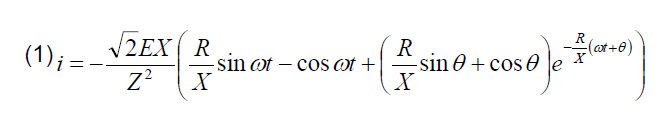
Reactance X, which is a measure of the inertia of the circuit, equals the sum of the reactance of the primary transformer winding X1 and the reactance of the power supply line Xs. The inrush current for the entire duration of its wave is damped by the constant resistance of the primary transformer winding, R1 (if changes in resistance related to the heating of the winding are ignored), and the resistance of the power supply line, Rs.
Fig.1. The course of the inrush current impulse and changes in resistance of the HTS transformer windings during its duration, as well as the voltage of the power supply line and the magnetic flux in the transformer core; RHTS – primary winding resistance of the superconductor transformer, e – supply voltage, φ – low in the transformer core, iHTS – unidirectional inrush current impulse, Φn – core saturation flow value Φr – residual magnetic flux value at the moment of transformer switching on, Ic – the critical current of the transformer primary winding, Icw – the current at which the winding returns to the superconducting state
When analyzing the damping phenomenon of the HTS transformer inrush current, during one impulse of the inrush current, three intervals should be distinguished (Fig. 1): I – the current impulse has not exceeded the critical value of the winding current, the winding is in the superconducting state and its resistance is equal to zero (R1HTS=0 Ω), II – the current impulse has exceeded the critical value and the winding has changed to a resistive state (R1HTS>0 Ω), III – the current impulse is lower than the critical value and the winding has returned to superconductivity (R1HTS=0 Ω).
It therefore follows that in the I and III intervals, the inrush current is only damped by the resistance of the supply network Rs. In the interval II, the resistance damping the inrush current impulses is the sum of resistance of the power supply line Rs and resistance of the primary winding R1HTS in its resistive state.
Power supply line resistance has a greater impact on the value and duration of the HTS transformer inrush current than in the case of a conventional transformer. During the rise of the inrush current impulse, when the HTS transformer windings are in the superconducting state (interval I, Fig. 1), the current is only damped by the resistance of the power supply line. The value of this resistance determines whether the current impulse exceeds the critical value for the HTS winding and how long it will last.
Investigation of HTS transformer
A single-phase HTS transformer with a power of 13.8 kVA has been tested (Fig. 2) [7]. The rated voltage of the primary (HV) and secondary (LV) windings is 230 V and 60 V, respectively. The rated current of the primary (HV) winding is 60 A, and that of the secondary (LV) winding is 230 A. The nominal parameters are to be found in Table I. The transformer’s primary winding was made with the SCS4050-AP superconducting tape, with a minimum critical current of 87 A at 77 K, in the own field. The secondary winding was made with SCS12050-AP tape with a minimum critical current of 333 A. Parameters of windings are given in Table II.
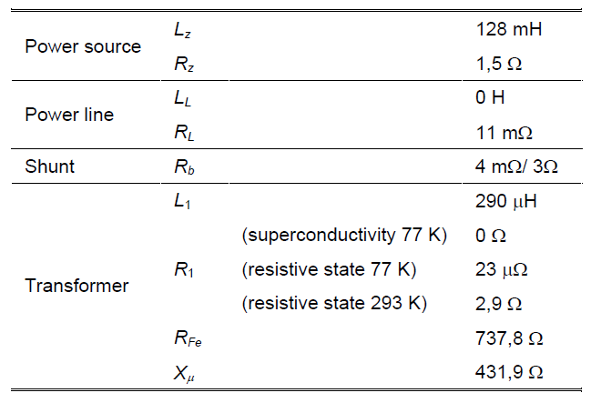
The measurements were made in a circuit as shown in Figure 3. The resistance of the power supply line was being changed by including resistors of 4 mΩ and 3 Ω in the current circuit. Circuit parameters are given in Table III.
Table I. Transformer’s nominal data
Table II. Windings parameters
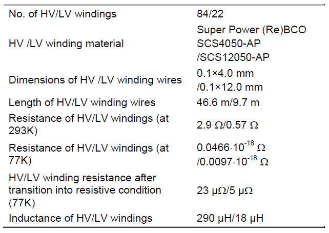
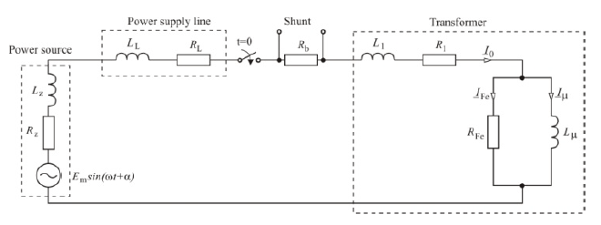
Table III. Parameters of the power circuit
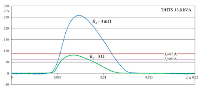
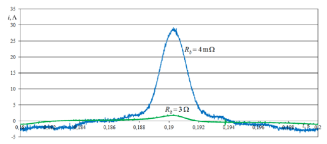
The pulse of the first impulse of the inrush current recorded in the measurements is shown in Figure 4. With a power supply line resistance of 15 mΩ, the current impulse exceeds by 170 A the critical value of the primary winding current of 87 A. After increasing the resistance of the power line to 3.1 Ω, the first current pulse reaches 81 A and does not exceed the critical current value for the winding. At this resistance value, the inrush current disappears completely for 10th pulse (Fig. 5), i.e. after 0.18 ms, while for resistance 15 mΩ, this is only done after 4 seconds.
Numerical analysis
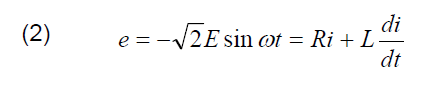
The high stochasticity of the results of the measurement of characteristic parameters of the inrush current wave significantly impedes the analysis of the impact of impedance changes in the power supply line. The equations describing the waveform of the inrush current of the HTS transformer have been derived. The starting point was the general equation (2) of the circuit from Figure 3, analyzed in the intervals I, II and III given in Figure 1, taking the boundary conditions into account.
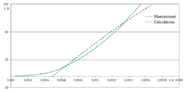
In the numerical analysis, good compliance with the measurement results has been obtained (Fig. 6). The relative error between the maximum value measured and the calculated value is 1.3% for the first impulse and 8.2% and 0.4% for the subsequent ones, respectively. The relative error of the duration of the first impulse is 7.6%, followed by 8.1% and 8.5% for the subsequent ones.
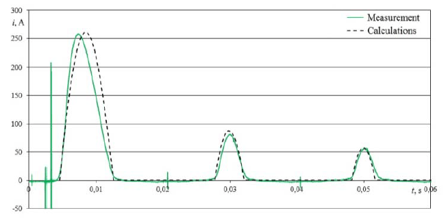
Differences in the inrush current impulses obtained from the calculations, especially visible in the non-current breaks (Fig. 6) but also in the shape of pulses (Fig. 7), result from omitting the determined component of the current, i.e. the idling current of the transformer and from the omission of the influence of the shape of the magnetic hysteresis loop of the core.
Numerical analysis of impedance changes of the power supply line of the HTS transformer with the power of 13.8 kVA on the waveform of the inrush current and its individual impulses was carried out. The change in the resistance of the line has the greatest influence on the waveform of the inrush current and its individual impulses (Fig. 8 and Fig. 10). The change in the inductance of the network has a smaller influence (Fig. 9 and Fig. 11).
A change of the line resistance by +50 mΩ, -100 mΩ (at constant inductance value) has a small influence on the maximum value of the first current impulse (Fig. 8) and its duration (Fig. 10). The maximum value of the first impulse changes accordingly by +23 A, -10 A and the duration of the impulse by +0.53 ms, -0.23 ms. For almost the entire duration of this impulse, the windings of the HTS transformer are in a resistive state and their resistance plays a decisive role in damping the inrush current.
A significant influence of the power supply line resistance occurs for the second and subsequent impulses, when the HTS transformer windings are in a superconducting state for a relatively short time, or when they maintain this state all the time. The reduction of the line resistance by 100 mΩ significantly increases the maximum value of the second and subsequent impulses of the inrush current and extends the time of the current wave decay. The first three impulses then exceed the critical value of the current (87 A) of the transformer’s primary winding.

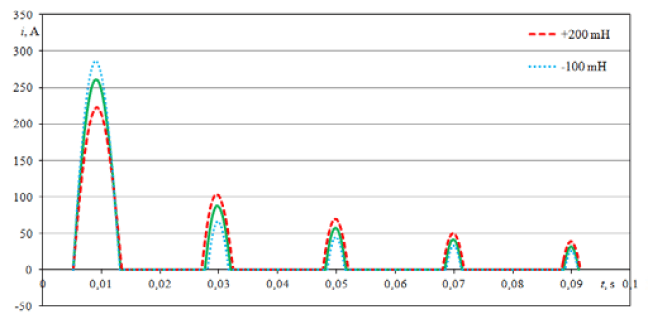
Changing the inductance of the power supply line (at a constant resistance value) has a lesser influence on the waveform of the inrush current than the change of its resistance. The greatest effect of the change in the inductance of the line occurs for the first impulse of the inrush current and decreases for subsequent pulses. The change of the network inductance by +200 mH, -100 mH causes, respectively, a change in the maximum value of the first current impulse by +25 A, -39 A and a change in its duration by +0.29 ms, -0.19 ms (Fig. 11). Increase in the maximum value of the first current impulse and decrease the second and subsequent ones while reducing the inductance is characteristic (Fig. 9). When increasing the inductance, the effect is reversed. The reduction of the inductance of the power supply line also entails a shortening of the duration of the inrush current impulses.
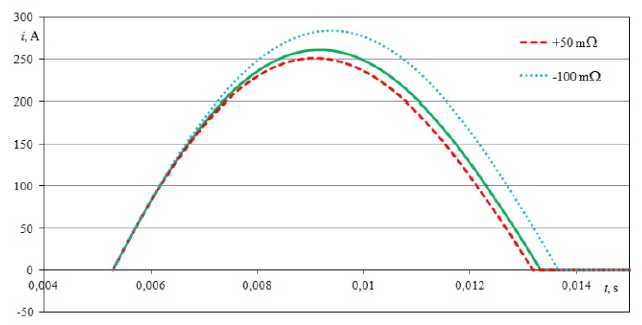
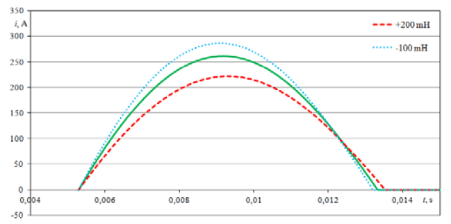
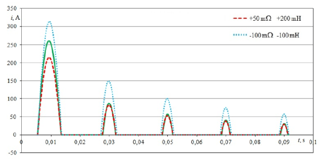
Figure 12 shows the course of the first five impulses of the inrush current with change of the impedance of the power supply line for two cases: 1) when the resistance of the line was increased by +50 mΩ and inductance was increased by +200 mH, 2) the resistance and inductance of the line were simultaneously decreased by -100mΩ and – 100mH, respectively.
Summary
The impedance of the power supply line is a parameter significantly influencing the maximum value and duration of the inrush current of the HTS transformers.
During the rising and falling edge of the inrush current impulse, when the HTS transformer windings are in a superconducting state, and, therefore, when their resistance is zero, the resistance of the power supply line is the only parameter that is responsible for damping the current impulses. After exceeding the critical current of the windings, i.e after their transition to a resistive state, the resistance of the line has less influence on the current attenuation. The transformer’s winding resistance, which can reach multiple times higher values than the network resistance, has a significant influence on the inrush current. In the case of current impulses that do not exceed the critical value of the HTS winding current, and, therefore, when the transformer windings are in the superconducting state, only the resistance of the line is responsible for attenuation of the inrush current wave. At low values of the line resistance and zero resistance of HTS windings, the inrush current of the superconductor transformer can reach very long durations.
While the increase in the resistance of the power supply line entails a reduction of the maximum inrush current and the reduction of its duration, the influence of changes in the inductance of the line is more complex. Increasing the inductance of the line causes the reduction of the maximum value of the first few impulses of the HTS transformer inrush current and the increase of the maximum value of the remaining impulses. This increases the number of current impulses with a maximum value exceeding the critical value of the HTS windings. The higher inductance of the power supply line translates into a longer duration of individual impulses of the inrush current and a longer duration of its wave.
The research was conducted in scope of the project “Analysis of inrush current phenomenon and the phenomena related in superconducting transformers.” The project was financed with means of National Science Center given with the decision no. DEC- 2012/05/D/ST8/02384.
REFERENCES
[1] V. Selvamanickam, Y. Xie, „Progress in scale-up of 2G HTS wire at SuperPower,” Dept. of Energy Annual Review, Superconductivity for Electrical Systems, Arlington, VA, July 29-31, 2008.
[2] Y. Xie, M. Marchevsky, X. Zhang, K. Lenseth, Y. Chen, X. Xiong, Y. Qiao, A. Rar, B. Gogia, R. Schmidt, A. Knoll, V. Selvamanickam, G. Ganesan Pethuraja, P. Dutta, „Second-generation HTS conductor design and engineering for electrical power applications,” IEEE Transactions on Applied Superconductivity, vol. 19, no. 3, June 2009.
[3] R. A. Turner, K. S. Smith, „Transformer inrush currents,” IEEE Industry Applications Magazine, vol. 16, no. 5, pp. 14–19, 2010.
[4] L. Prikler, G. Bánfai, G. Bán, P. Becker, „Reducing the magnetizing inrush current by means of controlled energization and de-energization of large power transformers,” Electric Power Systems Research, vol. 76, no. 8, pp. 642-649, 2006.
[5] M. Steurer, K. Frohlich, „The impact of inrush currents on the mechanical stress of high voltage power transformer coils,” IEEE Transactions on Power Delivery, vol. 17, no. 1, pp. 155-160, August 2002.
[6] T. R. Specht, „Transformer inrush and rectifier transient currents,” IEEE Transactions on Power Apparatus and Systems, vol. PAS-88, iss. 4, pp. 269-276, April 1969.
[7] G. Komarzyniec, „14 kVA superconducting transformer with (RE)BCO windings transformers,” 2017 International Conference on Electromagnetic Devices and Processes in Environment Protection with Seminar Applications of Superconductors (ELMECO & AoS), IEEE Conferences, s. 1–4, Nałęczów, 3–6 grudnia 2017.
Authors: Grzegorz Komarzyniec, PhD, e-mail: g.komarzyniec@pollub.pl, Lublin University of Technology, Institute of Electrical Engineering and Electrotechnologies, Nadbystrzycka 38a, 20-618 Lublin,
Source & Publisher Item Identifier: PRZEGLĄD ELEKTROTECHNICZNY, ISSN 0033-2097, R. 94 NR 12/2018. doi:10.15199/48.2018.12.55
