Published by Dániel MARCSA, eCon Engineering Kft., Hungary
Abstract. Transformer noise is a significant contribution to unwanted ambient noise, especially in the vicinity of the electrical transmission facility. It is therefore very important to get to know the mechanism of noise generation of the distribution transformer. As outcomes of this work, a finite element based multiphysics model is presented which provides a convenient and efficient toolchain for simulating the transformer sound emission mechanism. Finally, the operation of modelling chain is presented on a 200kVA distribution transformer simulation.
Streszczenie. Hałas transformatora ma znaczący wpływ na niepożądany hałas otoczenia, zwłaszcza w pobliżu instalacji przesyłowej prądu elektrycznego. Z tego powodu ważnym jest poznanie mechanizmu generowania szumu transformatora rozdzielczego. Jako wynik tej pracy przedstawiono model transformatora rozdzielczego 200 kVA oparty na analizie elementów skończonych, który zapewnia wygodny i wydajny zestaw narzędzi do symulacji mechanizmu emisji dźwięku z analizowanego urządzenia. (Analiza hałasu i wibracji transformatora rozdzielczego).
Keywords: Noise and vibration, finite element analysis, coupled simulation, distribution transformer, ANSYS.
Słowa kluczowe: hałas i wibracje, analiza elementów skończonych, symulacja sprzężona, transformator dystrybucyjny, ANSYS.
Introduction
Distribution transformers are one of the most critical components for electrical energy transportation and distribution. The vibration and noise of these electric machines increasingly interested designers and manufacturers. It is therefore critical that manufacturers are able to accurately identify the acoustic characteristics of a transformer before production commences. However, the various physical phenomena are strongly related in the transformers, as illustrated in Fig. 1, so only the multiphysics or coupled numerical simulation can be useful to get knowledge about these effects. Further, safety regulations require that the noise level is kept within a certain range.
The study of noise and vibration in transformers began in the 1930s, mainly by transformer manufacturers [1]. These works are focused on mainly the measurement of transformer noise. In recent years, thanks to the computer capabilities and software, more and more attention has been paid to the numerical simulation of these unwanted effects. However, most of these works are separated the strongly coupled sources or effects of noise and vibration. The noise mainly originates from the magnetostrictive effect of the steel sheet [2], [3] and the shape of the core [4]. The electromagnetic force produced in the windings also important as electromagnetic noise source [5]. The clamping stress and natural frequencies of core and tank also have some effect on vibration [6]. These effects result in deformation of the tank [7], [8], which cause disturbing audible sound. When using coupled or multiphysics simulation, important effects are neglected or analysed only a special load case. Most of the time, the permeability of the transformer core is isotropic [5], [9] or analysed the shortcircuit state of transformer [5], [10]. But a coupled simulation workflow with the whole noise generation process at nominal operation has not been studied.
This work focuses on distribution transformer coupled simulation with the help of the finite element method (FEM) [10], [11]. The aim of this paper is to develop a numerical methodology that accurately predicts the vibration and acoustic characteristic of a distribution transformer under normal operation condition. The modelling procedure is based on the chaining of three analysis methods, the electromagnetic, the mechanical and the acoustic simulations as you can see in Figure 1. The weak or series coupling was used for the connection because in this case completely identical geometry is not needed, finite element mesh and solver options are independent for each analysis.
The workflow of the transformer simulation was established using ANSYS Workbench environment. The auxiliary noise sources are not taken into account.
Transformer Coupled Simulation
The geometry of the 200kVA distribution transformer with the sectioned tank is shown in Fig 2a. The transformer core is composed of oriented silicon steel sheets, and the anisotropy of silicon steel sheets should be considered. The B-H curve and magnetostrictive curve of steel sheet in rolling and transverse direction are shown in Fig 3. The key parameters of the transformer are summarized in Table 1.
Table 1. Main technical parameters of the analysed oil-type transformer.
The simulation chain starts with time-dependent nonlinear electromagnetic simulation. The external circuit of excitation and load is directly coupled to the finite element model. The geometry (the active part of the transformer) of the problem is discretized into 273823 tetrahedron elements. The numerical solution of these equations is based on ungauged T, Φ – Φ – formulation [11], [12],

where [σ] and [μ] is the conductivity and permeability tensor, T0 is the impressed current vector potential, T is the current vector potential, and HP is the additional field component due to core loss.
The main task of this step is to calculate the Maxwell force and the Lorentz force in the core and windings, respectively. In addition, the different power losses (stranded, eddy current, hysteresis) in the core and the winding can also be determined in this step. The visualization of the magnetic flux density vectors in the core can be seen in Fig. 2b.
The next step is mechanical simulation in the frequency domain. However, resonance in the transformers may be induced when the multiples of excitation frequency are sufficiently close to the natural frequency [6], therefore it should be carried out the modal analysis. The main origin of vibration is the magnetostrictive strain, so the most critical frequency is 100 Hz. The modal analysis results are shown in Fig. 4, where it can be seen that both of them one frequency cannot avoid the 100 Hz.

Using the results of the electromagnetic simulation (magnetostriction, Lorentz force) and the natural frequencies from the modal analysis the mechanical displacement is evaluated by harmonic analysis. The solved generalized equation of motion is given as [4]
where Mu is the structural mass matrix, Cu is the viscous damping matrix, Ku is the stiffness matrix, ü , u̇ , u is the nodal acceleration, nodal velocity and nodal displacement vector, respectively. fe is the spectrum of force from the electromagnetic simulation as load force.
The basic procedure to pass the electromagnetic results from the time domain to the frequency domain mechanical simulation is the Fourier transform [10] of results. The vibration from the core due to magnetostriction contains a 100Hz component (twice the frequency of power source frequency) and harmonics, while the vibration from the winding has mainly a pure 100 Hz tone if the current in the winding themselves are free of harmonics [13].
Figure 5 shows the total deformation of the active parts of the transformer at 100 Hz. The deformation of core and clamp can be seen in Fig 5a and the deformation of the primary and secondary winding in Fig 5b. The maximal deformation at the core is in the upper yoke, where the displacement is greater than 3.5 μm. The maximum of displacement in the windings is right one (Phase C). The maximum deformation of this winding is 3.1 μm.
Finally, using the harmonics displacement, we determine the resulting pressure level of acoustic waves propagation through the insulation oil, the tank and the surrounding air. The nodal velocities of active part from the harmonic analysis have been interpolated and mapped to the acoustic mesh of oil. Fig. 6 illustrates the velocity vectors on the oil inner surface. The numerical prediction of sound radiation has required the oscillation of the transformer tank. Therefore, it is necessary the coupling of (3) and the Navier-Stokes equation of fluid momentum and the flow continuity equation,


where ρ0 is the mean fluid density, Mq is the fluid mass matrix, Cq is the fluid damping matrix, Kq is the fluid stiffness matrix, fq and fu is the load force and Cfs is the fluid-structure coupling term. The pressure is p = q̇ = jωq.
Results and Discussion
The main sources of vibration are the electromagnetic origin, so the accuracy of the electromagnetic model is important. The loss has been used to validate the model. The calculated total loss is 2076 W, which corresponds to the value specified in the datasheet (see in Table I). The main reason for the difference is that there is no information on the load used for the measurement, and an average distribution network as load used in the finite element simulation.
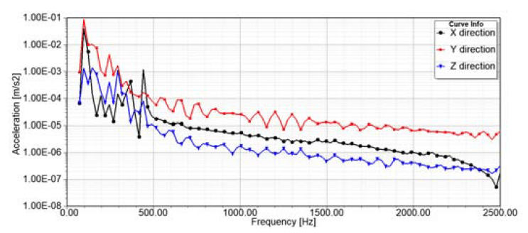
Fig. 7 and 8 show the results of mechanical harmonic analysis at two specific points on the transformer. These figures show the spectrum of x-, y- and z-component of the acceleration. As the modal analysis has shown, one of the resonance frequencies of the active part and the tank is close to twice the excitation frequency. This is also supported by Fig. 7 and 8, because one of the peak values of the acceleration spectrum is at 100 Hz. The tank top has another peak in the spectrum at 150 Hz. Based on this information, the sound pressure level is analysed at 100 Hz. Fig. 9 and 10 summarize the simulation results from the acoustic field simulation. These figures show the sound pressure level at 2 m from the tank wall. 0 degrees and – 180 degrees indicate the centre of the shorter side of the transformer. Reference line shows the 53 dB, which is the noise level of this transformer based on datasheet. These results also support that the accuracy of the result obtained by the numerical simulation is acceptable. As shown in the figures, the sound pressure reaches 60 dB in the 680 mm case. When using A-weighting [13], the sound pressure level increases as shown in Fig. 10. Based on the results, it can be stated that the analysed transformer meets the requirements, but its noise level can be reduced by proper design.
Conclusions
This paper analyzes the performance of noise and vibration in the distribution transformer considering the anisotropy and magnetostriction influence of silicon steel sheet. A three-dimensional finite element method based multiphysics workflow in the electromagnetic – mechanical – acoustic field is established using sequential coupling of ANSYS software. The operation of the 3-D finite element workflow is analyzed via a 200 kVA distribution transformer problem. It shows that the simulation is in a reasonable agreement with the transformer datasheet value, verifying the validity of the presented coupled simulation. The presented simulation workflow seems to be appropriate for simulating transformer noise and vibration or it may be helpful to develop new transformer diagnosing method.
The future plan is to further develop the presented workflow to take into account the structure-borne transmission of sound waves through the transformer mountings and auxiliary noise sources, e.g. oil pump. In addition, the speed up and simplification of simulation workflow also an ongoing task.
The research for this paper was financially supported by the EU and the Hungarian Government from the project “Intensification of the activities of HU-MATHS-IN – Hungarian Service Network of Mathematics for Industry and Innovation” under grant number EFOP-3.6.2-16-2017- 00015.
REFERENCES
[1] IEEE Commi t te Repor t , Bibliography on Transformer Noise, IEEE Transactions on Power Apparatus and Systems, PAS-87 (1968), 372-387
[2] Zhang P., Li L., Cheng Z., Tian C., Han Y., Study on Vibration of Iron Core of Transformer and Reactor Based on Maxwell Stress and Anisotropic Magnetostriction, IEEE Transactions on Magnetics, 55 (2019), No. 2, 9400205
[3] Chen D., Hou B., Feng Z., Bai B., Study of Magnetostrictive Influence of Electrical Sheet Steel Under
Different DC Biases, IEEE Transactions on Magnetics, 55 (2019), No. 2, 2001305
[4] Shuai P., B iela J., Impact of Core Shape and Material on the Acoustic Noise Emission of Medium Frequency, Medium Voltage Transformers, 17th European Conference on Power Electronics and Applications (EPE’15 ECCE-Europe), Geneva (2015), 1-11
[5] Duan X., Zhao T., Liu J., Zhang L., Zou L., Analysis of Winding Vibration Characteristics of Power Transformers Based on the Finite Element Method, Energies, 11 (2018), No. 9, 2404
[6] Hsu C.-H., Lee S.-L., Lin C.C., Liu C.-S., Chang S.-Y.,
Hsieh M.-F., Huanf Y.-M., Fu C.-M., Reduction of Vibration and Sound-Level for a Single-Phase Power Transformer with Large Capacity, IEEE Transactions on Magnetics, 51 (2015), No. 11, 8403204
[7] Vieira N., Antunes P.J., Martins C., Dias G.R., Coelho A.T., Vibro-Acoustic Analysis of a Distribution Power
Transformer Using the Finite Element Method, CWIEME 2008 – Coil Winding, Insulations & Electrical Manufacturing, Berlin (2008), 1-10
[8] Shengchang J., Lingyu Z., Yanming L., Study on Transformer Tank Vibration Characteristics in the Field and Its Application, Przegląd Elektrotechniczny, 2011 (2011), No. 2, 205-211
[9] Kubiak W., Wi tc zak P., Vibration Analysis of Small Power Transformer, COMPEL – The International Journal for Computation and Mathematics in Electrical and Electronic Engineering, 29 (2010), No. 4, 1116-1124
[10] Kaltenbacher M., Numerical Simulation of Mechatronic Sensors and Actuators, Springer-Verlag, Berlin, 2007
[11] Kuczmann M., I ványi A., The Finite Element Method in Magnetics, Akadémiai Kiadó, Budapest, 2008
[12] Lin D., Zhou P., Chen Q.M., Lambert N., Cendes Z.J., The Effects of Steel Lamination Core Losses on 3D Transient Magnetic Fields, IEEE Transactions on Magnetics, 46 (2010), No. 8, 3539-3542
[13] Tímár P.L., Fazekas A., Kiss J., Miklós A., Yang S.J., Noise and Vibration of Electrical Machines, Akadémiai Kiadó, Budapest, 1989
Author: dr. Dániel Marcsa, Ph.D., eCon Engineering Kft., Kondorosi u. 3, Budapest, H-1116, Hungary, E-mail: daniel.marcsa@econengineering.com.
Source & Publisher Item Identifier: PRZEGLĄD ELEKTROTECHNICZNY, ISSN 0033-2097, R. 95 NR 12/2019. doi:10.15199/48.2019.12.38
