Published by Electrical Installation Wiki, Chapter J. Overvoltage protection – Design of the electrical installation protection system
To protect an electrical installation in a building, simple rules apply for the choice of
• SPD(s);
• its protection system.
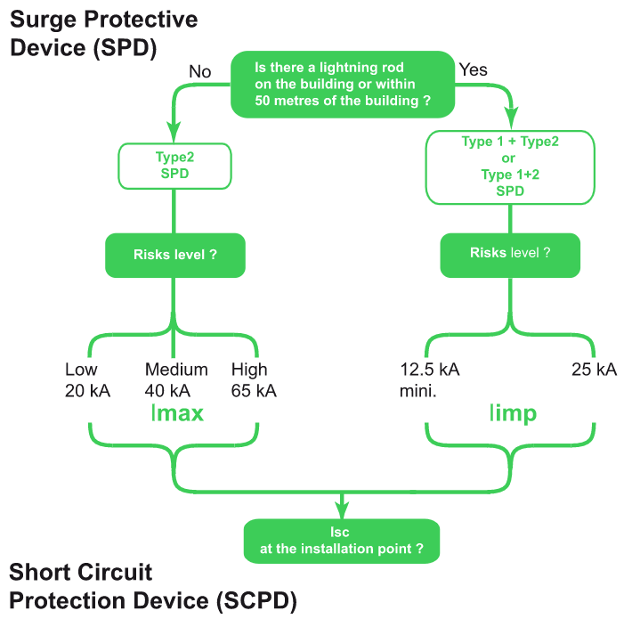
For a power distribution system, the main characteristics used to define the lightning protection system and select a SPD to protect an electrical installation in a building are:
• SPD
– quantity of SPD
– type
– level of exposure to define the SPD’s maximum discharge current Imax.
• Short circuit protection device
– maximum discharge current Imax;
– short-circuit current Isc at the point of installation.
The logic diagram in the Figure J20 below illustrates this design rule.
The other characteristics for selection of a SPD are predefined for an electrical installation.
• number of poles in SPD;
• voltage protection level Up;
• operating voltage Uc.
This sub-section Design of the electrical installation protection system describes in greater detail the criteria for selection of the protection system according to the characteristics of the installation, the equipment to be protected and the environment.
Elements of the protection system
A SPD must always be installed at the origin of the electrical installation.
Location and type of SPD
The type of SPD to be installed at the origin of the installation depends on whether or not a lightning protection system is present. If the building is fitted with a lightning protection system (as per IEC 62305), a Type 1 SPD should be installed.
For SPD installed at the incoming end of the installation, the IEC 60364 installation standards lay down minimum values for the following 2 characteristics:
• Nominal discharge current In = 5 kA (8/20) µs;
• Voltage protection level Up (at In) < 2.5 kV.
The number of additional SPDs to be installed is determined by:
• the size of the site and the difficulty of installing bonding conductors. On large sites, it is essential to install a SPD at the incoming end of each subdistribution enclosure.
• the distance separating sensitive loads to be protected from the incoming end protection device. When the loads are located more than 10 meters away from the incoming-end protection device, it is necessary to provide for additional fine protection as close as possible to sensitive loads. The phenomena of wave reflection is increasing from 10 meters see Propagation of a lightning wave
• the risk of exposure. In the case of a very exposed site, the incoming-end SPD cannot ensure both a high flow of lightning current and a sufficiently low voltage protection level. In particular, a Type 1 SPD is generally accompanied by a Type 2 SPD.
The table in Figure J21 below shows the quantity and type of SPD to be set up on the basis of the two factors defined above.

Protection distributed levels
Several protection levels of SPD allows the energy to be distributed among several SPDs, as shown in Figure J22 in which the three types of SPD are provided for:
• Type 1: when the building is fitted with a lightning protection system and located at the incoming end of the installation, it absorbs a very large quantity of energy;
• Type 2: absorbs residual overvoltages;
• Type 3: provides “fine” protection if necessary for the most sensitive equipment located very close to the loads.
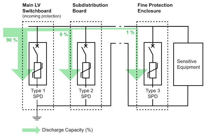
Note: The Type 1 and 2 SPD can be combined in a single SPD
Common characteristics of SPDs according to the installation characteristics
Operating voltage Uc
Depending on the system earthing arrangement, the maximum continuous operating voltage Uc of SPD must be equal to or greater than the values shown in the table in Figure J23.
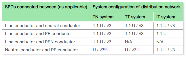
N/A: not applicable
U: line-to-line voltage of the low-voltage system
a.^1,2 these values are related to worst-case fault conditions, therefore the tolerance of 10 % is not taken into account.
The most common values of Uc chosen according to the system earthing arrangement.
TT, TN: 260, 320, 340, 350 V
IT: 440, 460 V
Voltage protection level Up (at In)
The IEC 60364-4-44 standard helps with the choice of the protection level Up for the SPD in function of the loads to be protected. The table of Figure J24 indicates the impulse withstand capability of each kind of equipment.
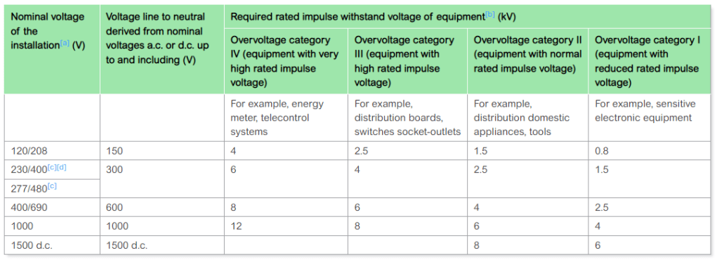
a.^ According to IEC 60038:2009.
b.^ This rated impulse voltage is applied between live conductors and PE.
c.^1,2 In Canada and USA, for voltages to earth higher than 300 V, the rated impulse voltage corresponding to the next highest voltage in this column applies.
d.^ For IT systems operations at 220-240 V, the 230/400 row shall be used, due to the voltage to earth at the earth fault on one line.
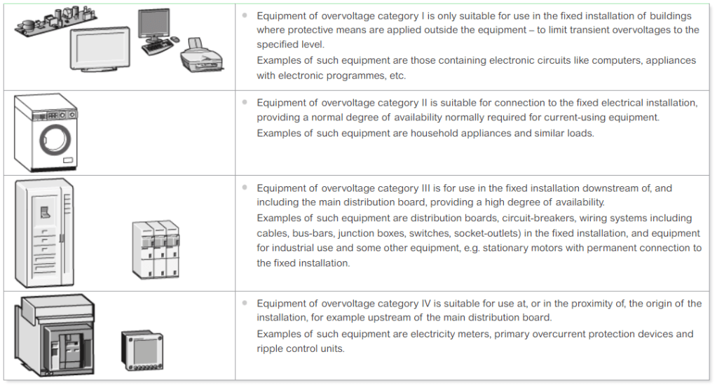
The “installed” Up performance should be compared with the impulse withstand capability of the loads.
SPD has a voltage protection level Up that is intrinsic, i.e. defined and tested independently of its installation. In practice, for the choice of Up performance of a SPD, a safety margin must be taken to allow for the overvoltages inherent in the installation of the SPD (see Figure J26 and Connection of Surge Protection Device).
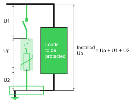
The “installed” voltage protection level Up generally adopted to protect sensitive equipment in 230/400 V electrical installations is 2.5 kV (overvoltage category II, see Fig. J27).
Note: If the stipulated voltage protection level cannot be achieved by the incoming-end SPD or if sensitive equipment items are remote (see Elements of the protection system#Location and type of SPD Location and type of SPD , additional coordinated SPD must be installed to achieve the required protection level.
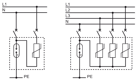
Number of poles
• Depending on the system earthing arrangement, it is necessary to provide for a SPD architecture ensuring protection in common mode (CM) and differential mode (DM).
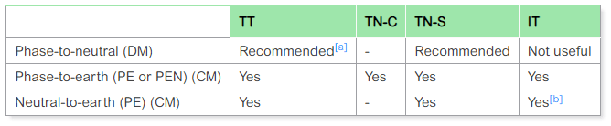
a.^ The protection between phase and neutral can either be incorporated in the SPD placed at the origin of the installation, or be remoted close to the equipment to be protected
b.^ If neutral distributed
Note:
• Common-mode overvoltage
A basic form of protection is to install a SPD in common mode between phases and the PE (or PEN) conductor, whatever the type of system earthing arrangement used.
• Differential-mode overvoltage
In the TT and TN-S systems, earthing of the neutral results in an asymmetry due to earth impedances which leads to the appearance of differential-mode voltages, even though the overvoltage induced by a lightning stroke is common-mode.
2P, 3P and 4P SPDs
(see Fig. J28)
• These are adapted to the IT, TN-C, TN-C-S systems.
• They provide protection merely against common-mode overvoltages.
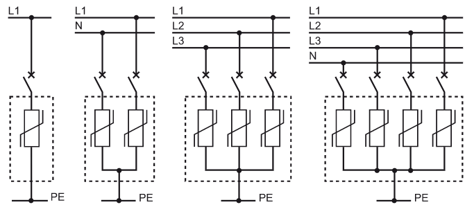
1P + N, 3P + N SPDs
(see Fig. J29)
• These are adapted to the TT and TN-S systems.
• They provide protection against common-mode and differential-mode overvoltages
Selection of a Type 1 SPD
Impulse current Iimp
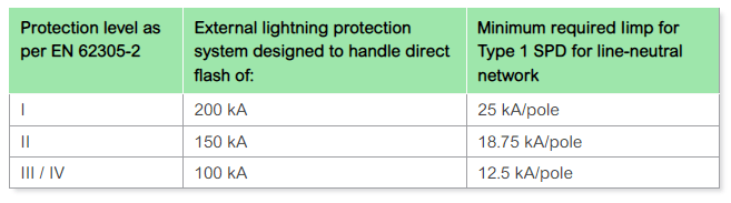
• Where there are no national regulations or specific regulations for the type of building to be protected: the impulse current Iimp shall be at least 12.5 kA (10/350 µs wave) per branch in accordance with IEC 60364-5-534.
• Where regulations exist: standard IEC 62305-2 defines 4 levels: I, II, III and IV
The table in Figure J31 shows the different levels of Iimp in the regulatory case.
Autoextinguish follow current Ifi
This characteristic is applicable only for SPDs with spark gap technology. The autoextinguish follow current Ifi must always be greater than the prospective short-circuit current Isc at the point of installation.
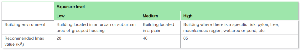
Selection of a Type 2 SPD
The maximum discharge current Imax is defined according to the estimated exposure level relative to the building’s location.
The value of the maximum discharge current (Imax) is determined by a risk analysis (see table in Figure J32).
Selection of external Short Circuit Protection Device (SCPD)
• The protection devices (thermal and short circuit) must be coordinated with the SPD to ensure – reliable operation, i.e.
– ensure continuity of service:
– withstand lightning current waves
– not generate excessive residual voltage.
• ensure effective protection against all types of overcurrent:
– overload following thermal runaway of the varistor;
– short circuit of low intensity (impedant);
– short circuit of high intensity.
Risks to be avoided at end of life of the SPDs
Due to ageing
In the case of natural end of life due to ageing, protection is of the thermal type. SPD with varistors must have an internal disconnector which disables the SPD.
Note: End of life through thermal runaway does not concern SPD with gas discharge tube or encapsulated spark gap.
Due to a fault
The causes of end of life due to a short-circuit fault are:
• Maximum discharge capacity exceeded.
This fault results in a strong short circuit.
• A fault due to the distribution system (neutral/phase switchover, neutral disconnection).
• Gradual deterioration of the varistor.
The latter two faults result in an impedant short circuit.
The installation must be protected from damage resulting from these types of fault: the internal (thermal) disconnector defined above does not have time to warm up, hence to operate.
A special device called “external Short Circuit Protection Device (external SCPD)”, capable of eliminating the short circuit, should be installed. It can be implemented by a circuit breaker or fuse device.
Characteristics of the external SCPD
The external SCPD should be coordinated with the SPD. It is designed to meet the following two constraints:
Lightning current withstand
The lightning current withstand is an essential characteristic of the SPD’s external Short Circuit Protection Device.
The external SCPD must not trip upon 15 successive impulse currents at In.
Short-circuit current withstand
• The breaking capacity is determined by the installation rules (IEC 60364 standard):
The external SCPD should have a breaking capacity equal to or greater than the prospective short-circuit current Isc at the installation point (in accordance with the IEC 60364 standard).
• Protection of the installation against short circuits
In particular, the impedant short circuit dissipates a lot of energy and should be eliminated very quickly to prevent damage to the installation and to the SPD.
The right association between a SPD and its external SCPD must be given by the manufacturer.
Installation mode for the external SCPD
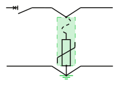
Device “in series”
The SCPD is described as “in series” (see Fig. J33) when the protection is performed by the general protection device of the network to be protected (for example, connection circuit breaker upstream of an installation).
Device “in parallel”
The SCPD is described as “in parallel” (see Fig. J34) when the protection is performed specifically by a protection device associated with the SPD.
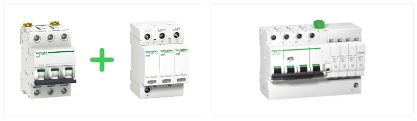
• The external SCPD is called a “disconnecting circuit breaker” if the function is performed by a circuit breaker.
• The disconnecting circuit breaker may or may not be integrated into the SPD.
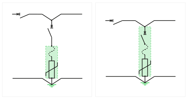
Note: In the case of a SPD with gas discharge tube or encapsulated spark gap, the SCPD allows the current to be cut immediately after use.
Guarantee of protection
The external SCPD should be coordinated with the SPD, and tested and guaranteed by the SPD manufacturer in accordance with the recommendations of the IEC 61643-11 standard. It should also be installed in accordance with the manufacturer’s recommendations. As an example, see the Schneider Electric SCPD+SPD coordination tables.
When this device is integrated, conformity with product standard IEC 61643-11 naturally ensures protection.
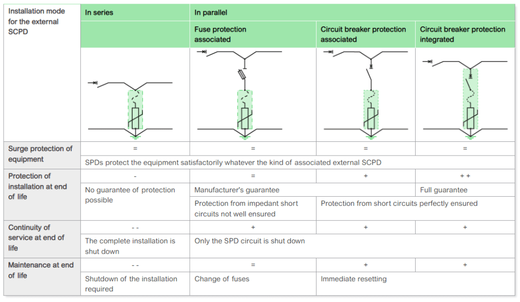
Summary of external SCPDs characteristics
A detailed analysis of the characteristics is given in section Detailed characteristics of the external SCPD .
The table in Figure J36 shows, on an example, a summary of the characteristics according to the various types of external SCPD.
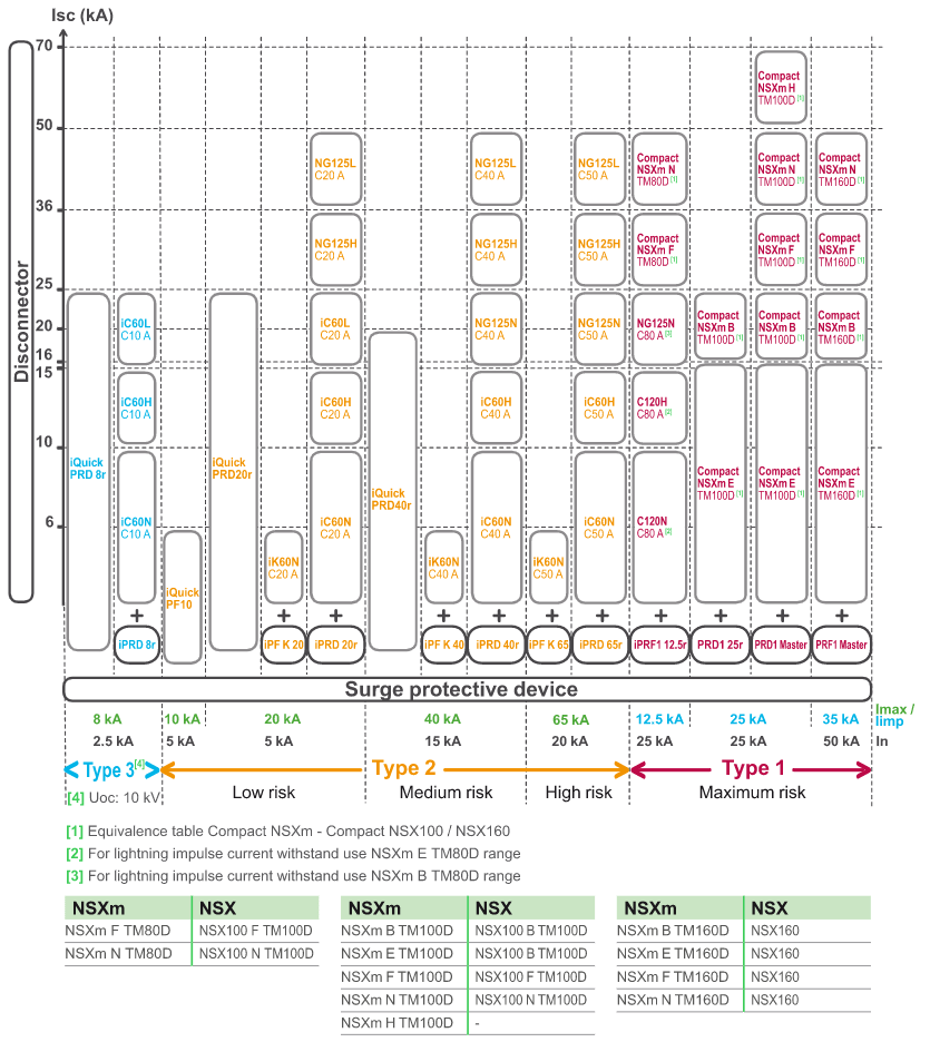
SPD and protection device coordination table
The table in Figure J37 below shows the coordination of disconnecting circuit breakers (external SCPD) for Type 1 and 2 SPDs of the Schneider Electric brand for all levels of short-circuit currents.
Coordination between SPD and its disconnecting circuit breakers, indicated and guaranteed by Schneider Electric, ensures reliable protection (lightning wave withstand, reinforced protection of impedant short-circuit currents, etc.)
Coordination with upstream protection devices
Coordination with overcurrent protection devices
In an electrical installation, the external SCPD is an apparatus identical to the protection apparatus: this makes it possible to apply selectivity and cascading techniques for technical and economic optimization of the protection plan.
Coordination with residual current devices
If the SPD is installed downstream of an earth leakage protection device, the latter should be of the “si” or selective type with an immunity to pulse currents of at least 3 kA (8/20 μs current wave).
Source URL: https://www.electrical-installation.org/enwiki/Design_of_the_electrical_installation_protection_system
