Published by Michał MAJKA, Janusz KOZAK, Electrotechnical Institute
Abstract. The superconducting fault current limiter (SFCL) is a device allowing for a more effective use of the existing power network infrastructure. The limitation of short-circuit currents by the SFCL to safe levels will result in the network elements being susceptible to smaller electrodynamic and thermal overloads. This paper presents the electrical scheme, design and numerical model of the 15 kV class SFCL prototype.
Streszczenie. Nadprzewodnikowy ogranicznik prądu zwarciowego (NOPZ) jest urządzeniem pozwalającego na lepsze wykorzystanie istniejącej infrastruktury sieciowej. Ograniczenie przez prądów zwarciowych do bezpiecznego poziomu sprawi, że elementy sieci będą narażone na mniejsze przeciążenia cieplne i elektrodynamiczne. W artykule przedstawiono schemat elektryczny, projekt i model numeryczny prototypu ogranicznika na napięcie 15 kV. (Bezrdzeniowy nadprzewodnikowy ogranicznik prądu 15 kV 140 A).
Keywords: superconductivity, superconducting fault current limiter, SFCL, numerical analysis.
Słowa kluczowe: nadprzewodnictwo, nadprzewodnikowy ogranicznik prądu, SFCL, analiza numeryczna.
Introduction
The superconducting fault current limiter (SFCL) introduces minimal impedance to the power system under normal conditions and high resistance during faults, limiting short circuit current. The main duty of the SFCL is decreasing the fault current to safe level and avoid network instability. The electrodynamic forces occurring during the course of a fault current may damage the devices of the electric power system, such as transformers, generators or busbars in switching stations, within tens of milliseconds. Every such failure of an electric power network entails expensive and time-consuming repairs. Therefore, it is vital that the network’s operation be secured with a reliable protection system. A rapid increase of the resistance of a superconductor on crossing the current critical value Ic makes it possible to build reliable superconducting fault current limiters (SFCLs). SFCLs react very rapidly by limiting the first, the most dangerous, surge current during a current fault condition, thus protecting the devices of the electric power network from the dynamic effects of current faults. The SFCL responds before the first cycle peak and provides an effective means to limit excessive fault currents to safe levels without the disadvantages of conventional fault current mitigation methods.
The SFCLs provide an economic solution for protecting the devices of the electric power system against excessive short circuit currents in case of faults. The application of a SFCL leads to an increase of the allowable short-circuit power at the point of connection of new power generating sources, which is determined by the short-circuit parameters of the power network. This, in turn, will result in an increase of the capability of the power network for connecting distributed generation energy sources based on renewable energy sources. Present researches on current limiters focus on resistive type [5], inductive type [1], [2], [4], [6], [7] and limiters with a saturated core [10]. The drawback of the concept of inductive limiter with shielded core was insertion of a finite impedance in the line even during normal operation, and the large size and weight of the iron core [9]. The presented solution of a coreless construction reduces the weight of the device and the size of the primary copper winding and the voltage on the limiter during the normal operation is negligible [4].
The design of the SFCL
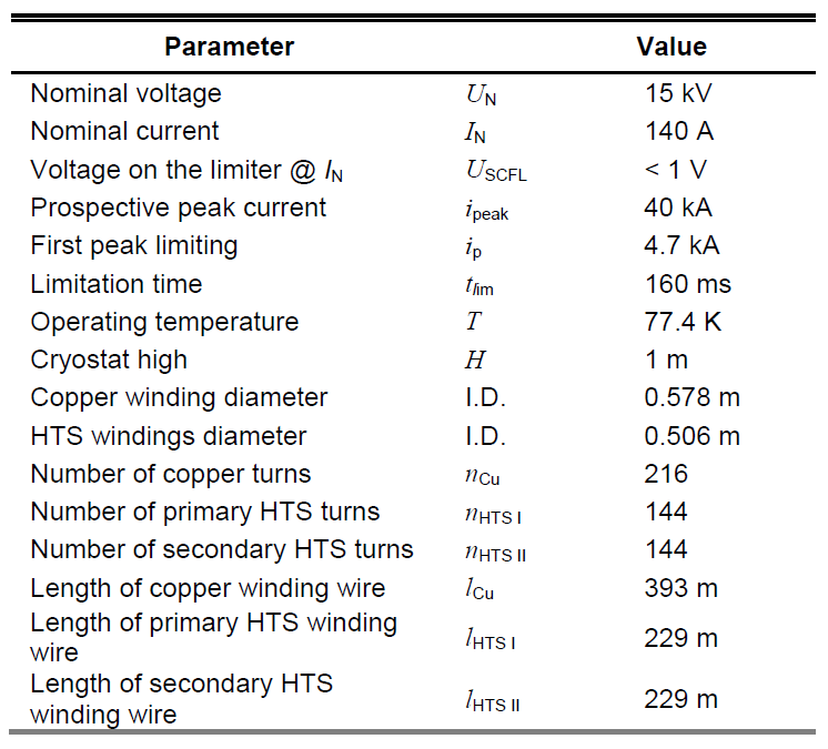
A design of a 1-phase inductive type superconducting limiter is presented in Figures 1-4. The limiter was designed to work in a 15 kV power system. Its main parameters are presented in table 1.


A three-winding superconducting current limiter has two primary windings and one secondary winding [1], [4]. The primary winding, placed on the outer ring, is made of a copper wire. The second primary winding, placed in the inner ring, is made of a 2G superconducting tape. The third winding is a shorted secondary winding made of a 2G superconducting tape, placed in the inner ring.

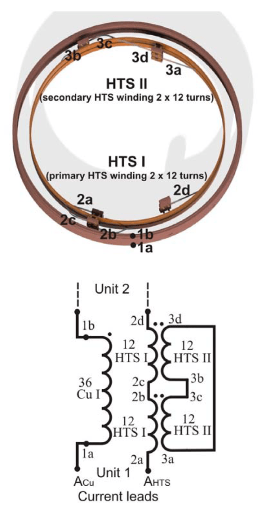
The primary winding made of 2G tape is connected in parallel with the copper primary winding. All three windings are magnetically coupled. The magnetic coupling between the 2G tape windings in the inner ring is greater than the magnetic coupling between the 2G tape winding and the copper winding in the outer ring. The coupling coefficient between primary HTS and secondary HTS windings is 0.97 and between primary copper winding and secondary HTS winding is about 0.52.
Table 1. Parameters of SFCL
The limiter will be placed in a cryostat with an external vacuum insulation and cooled in a liquid nitrogen bath (Fig. 1). The cryostat of the limiter will be made of GFRP (Glass Fiber Reinforced Polymer). It will be fitted with four copper current leads (Fig. 1) to which the primary, both copper and HTS, windings terminals will be connected. This will allow to record the distribution of currents in these windings during short-circuit tests.
The limiter consists of six identical modules connected in series (Fig. 1 – 4), which allows to lower the voltage of the individual windings. There is 2.5 kV per one module. The superconducting tapes will be insulated with 0.025 mm thick polyimide film with a 0.040 mm silicone adhesive during the winding process. Dielectric strength of DuPont Kapton FN polyimide film is 5.9 kV.
Each module consists of two carcasses of different diameters which are made of composite materials reinforced with fibreglass. The copper winding will be wound onto an external bobbin and the superconducting windings on an internal bobbin. In each of the six modules the primary copper winding has 36 turns and is connected in parallel with two primary superconducting windings. The primary superconducting windings have 12 turns each and are connected in series. The secondary superconducting windings consist of two shorted superconducting windings, each with 12 turns. Both the primary and the secondary superconducting windings are wound onto a single bobbin in such a way that their turns are positioned one on top of the other, which provides a very good magnetic coupling between the windings and this, in turn, reduces the voltage during the SFCL’s performance in nominal conditions.
The primary copper winding will be wound using a 3 mm x 6 mm copper wire. The superconducting windings will be wound using the SF12050 superconducting tape with 2 μm silver layer and a resistance of HTS tape 0.104 Ω/m in resistive state at 77.4 K [3]. The primary and secondary superconducting windings are of the same length and have the same number of turns. A Kapton tape will be used to insulate the superconducting windings. Figure 4 represent the connections of the windings of each of the six modules.
Numerical model of SFCL
The numerical model of the limiter was developed in the “Transient Magnetic” FEM-circuit Flux2D software [8]. The geometry of the actual model of the limiter was substituted with a simplified axially symmetric geometry (Fig. 5).


The outer circuit of the numerical model is presented in Fig. 6. The thermal issues which occur in the windings of the limiter are included in the user subroutine written in Fortran. According to this procedure, in every step in the calculations the temperature of the limiter’s winding is determined using the energy balance, based on the present value of the current flowing through the limiter’s windings. The energy balance equation takes into account the transition of the heat from the limiter windings to the cooling liquid. After determining the current temperature of the winding, the resistance of the winding is calculated on the basis of experimentally determined R(I,T) relation for the SF12050 superconducting tape [3].
Simulations were performed for model of limiter whose parameters are presented in table 1. Thanks to the performed simulations, courses of a fault current in the circuit with and without the limiter were obtained (Fig. 7), as well as the changes of resistance and temperature of individual limiter windings during the limitation of the fault current (Fig. 9).
In the stand-by state, i.e. the first 40 ms of calculations, the superconducting windings of the limiter are in the superconducting state and a nominal current of 140 A flows through the limiter (Fig. 8). The voltage value in all models of the limiter is lower than 1 V, which results from a minor leakage reactance.
During a short-circuit lasting from 0.040 sec. to 0.200 sec., a fault current flows through the limiter. The peak value of the current in the shorted circuit ip = 40 kA was limited to 4.7 kA (Fig. 7). The course of the fault current causes the HTS windings to heat up very rapidly. The temperature of the windings increases from an initial temperature of 77.4 K to a maximum temperature Tmax which is reached at the moment of switching off of the short-circuit (Fig. 9c).


The performed simulation shows that the temperature of the superconducting windings increases much faster than the temperature of the copper windings, and it reaches different values at the moment of switching off of the short-circuit. In designing the limiter, it was assumed that the maximum temperature of the limiter’s superconducting windings at the moment of a short-circuit occurrence would not exceed 200 K and the fault current peak value would be below 5 kA
Conclusion
The developed design in which the superconducting windings are wound simultaneously onto a single bobbin allows to obtain a very high coupling factor between the windings and minimize the leakage reactance of the limiter, which minimizes the voltage in the limiter in the stand-by state. In case of a 2-winding design in which the primary copper winding is magnetically coupled with a secondary HTS winding, there always occurs leakage reactance, which causes losses in the stand-by state. The use of a connection in parallel of a copper coil and a superconducting coil in the primary winding protects the short circuit from opening in case when the superconducting tape is damaged. The fault current limiting capability of a 3-winding limiter is determined mostly by the impedance of the copper winding coupled in parallel with the primary superconducting winding.
An analysis of the results of the numerical simulations confirmed that it is possible to build an inductive type coreless superconducting fault current limiter that will effectively limit the peak value of the fault current from 40 kA to 5 kA within 160 ms. The number of turns in the primary copper winding and the superconducting tape length in the superconducting windings must be such that the temperature of the HTS windings does not exceed the maximum allowed temperature of the superconducting tape. Due to a substantial increase of the temperature of the limiter’s HTS windings, the short circuit must be switched off by a conventional circuit breaker before the temperature of the HTS winding reaches the maximum value.
This work was supported in part by the National Centre for Research and Development under Grant UMO2012/05/B/ST8/01837.
REFERENCES
[1] Kozak J., Majka M., Janowski T., Kozak S., Wojtasiewicz G., Kondratowicz-Kucewicz B., “Tests and Performance Analysis of Coreless Inductive HTS Fault Current Limiters”, IEEE Trans. Appl. Supercond., 21 (2011), No. 3, 1303 – 1306.
[2] Naeckel O., Noe M., “Design and Test of an Air Coil Superconducting Fault Current Limiter Demonstrator ”, IEEE Trans. Appl. Supercond., 24 (2014), No. 3, article nr 5601605.
[3] Czerwinski D., Jaroszynski L., Majka M., Kozak J., “Analysis of Alternating Overcurrent Response of 2G HTS Tape for SFCL”, IEEE Trans. Appl. Supercond., 24 (2014), No. 3, 5600104
[4] Kozak J., Majka M., Kozak S., Janowski T., „Design and Tests of Coreless Inductive Superconducting Fault Current Limiter”, IEEE Trans. Appl. Supercond., 22 (2012), No. 3, 5601804
[5] Kozak J., Majka M., Kozak S., Janowski T., „Comparison of Inductive and Resistive SFCL”, IEEE Trans. Appl. Supercond., 23 (2013), No. 3, 5600604
[6] Heydari H., Sharifi R., “Three-Dimensional Pareto-Optimal Design of Inductive Superconducting Fault Current Limiters”, IEEE Trans. Appl. Supercond., 20 (2010), No. 5, 2301 – 2311
[7] Naeckel O., Noe M., “Conceptual Design Study of an Air Coil Fault Current Limiter ”, IEEE Trans. Appl. Supercond., 23 (2013), No. 3, article nr 5602404.
[8] de Sousa W.T.B., Nackel O., Noe M., “Transient Simulations of an Air-Coil SFCL”, IEEE Trans. Appl. Supercond., 24 (2014), article nr 5601807.
[9] Janowski T, Wojtasiewicz G., Kondratowicz-Kucewicz B., Kozak S., Kozak J., Majka M., „Superconducting Winding for Inductive Type SFCL Made of HTS Tape With Increased Resistivity”, IEEE Trans. Appl. Supercond., vol. 19, issue: 3, pp. 1884 – 1887, 2009.
[10] Hong H., Su B., Niu G.J., Cui J.B., B. Tian, Q., Wang L.Z., Wang Z.H., Zhang K., Xin Y., “Design, Fabrication, and Operation of the Cryogenic System for a 220 kV/300 MVA Saturated Iron-Core Superconducting Fault Current Limiter”, IEEE Trans. Appl. Supercond., vol. 24, issue: 5, article nr 9002204, 2014.
Authors: dr inż. Michał Majka, Instytut Elektrotechniki, ul. Pożaryskiego 28, 04-703 Warszawa, E-mail: m.majka@iel.waw.pl; dr hab. inż. Janusz Kozak, Instytut Elektrotechniki, ul. Pożaryskiego 28, 04-703 Warszawa, E-mail: j.kozaki@iel.waw.pl
Source & Publisher Item Identifier: PRZEGLĄD ELEKTROTECHNICZNY, ISSN 0033-2097, R. 92 NR 7/2016. doi:10.15199/48.2016.07.06
