Published by A. M. Shiddiq YUNUS1, Makmur SAINI1, Ahmed Abu-SIADA2, Mohammad A.S. MASOUM3,
State Polytechnic of Ujung Pandang (1), Indonesia
Curtin University (2), Australia
Utah Valley University(3), USA
Abstract. Wind energy becomes a popular source for renewable energy based power plants since a recent decade ago. Within many types of wind turbine generator (WTG), Doubly Fed Induction Generator currently dominating the market niche by about 64% on all installed capacity all around the world in 2015. A DFIG consists of two converters that linked by a capacitor or so-called as DC link that works to allow the transfer energy from WTG to the grid and vice versa. These converters are very sensitive to any faults particularly when the DC link voltage reach beyond the safety margin, it may be ended with the disconnection of DFIG to avoid any damage on the DFIG’s converters. This paper aims to investigate the impact of SMES Unit on DC link voltage of DFIG during various types and levels of faults. The study was conducted through a simulation program and shows that SMES Unit is very effective in reducing the voltage at DC link during grid swell events and slightly affecting the voltage overshoot during grid sag and short circuit events. For the last two cases, the SMES Unit control system is designed to work properly and optimally, therefore, impact of SMES rather insignificant due to the DC link voltages are within the safety margin, however, when DC particularly for the case where the DC link voltage tends to increase and potential to damage the switching parts of DFIG, the SMES Unit could significantly compensate the faults and maintain the voltage within the safety margin.
Streszczenie. W artykule analizowany jest wpływ układu SMES (superconducting magnetic energy storage) na pracę układu generatora DFIG typu. DC-link przy różnych typach zakłóceń na przykład zapadów napięcia lub zwarć w sieci. Układy konwerterów w systemie DFIG są bowiem bardzo czułen na przekroczenie przez napięcie marginesu bezpieczeństw co skutkować może odłączeniem generatora. Wpływ układu SMES na pracę generatora DFIG farmy wiatrowej przy różnych rodzajach zakłóceń
Keywords: DFIG, WTG, Grid Sag, Grid Swell, Short Circuit
Słowa kluczowe: farma wiatrowa, generator DFIG, SMES – superconducting magnetic energy storage
Introduction
Renewable energy sources become more popular since the last decade due to some efforts on mitigating global warming from the use of conventional energy sources for power plants. One of the popular renewable energy sources is wind energy, where it is reported in JRC Wind Energy Status Report 2016 Edition that there are about 430 GW wind turbine generators have been installed worldwide till 2016. Within all types of wind turbine generators, Doubly Fed Induction Generator (DFIG) become the most type installed worldwide which dominate about 64% of market share in 2015 [1]. This fact is based on the advantages of DFIG in terms of technical aspect where DFIG could supply some amount of reactive power to the grid as it is equipped with power electronics that connected directly to the grid and rotor side. With about 33% capacity of power electronics, the cost of the DFIG system becomes cheaper than its main rival in the same class, Full Converter Wind Turbine Generator (FCWTG) type [2]. A typical model of a DFIG can be seen in Fig 1.
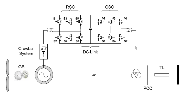
When wind turbines generators (WTGs) connected to the grid, there are some parameters must be complied to avoid the disconnection of WTGs to prevent any damages on the WTGs. For instance, voltage profile at the point of common coupling (PCC), rotors and stators’ current, DC link voltage (for DFIG and FCWTG), etc [3]. A DC link as shown in Fig. 1. is obligated to maintain the transfer energy between the rotor and grid [4]. DC link power electronic that links a grid side converter (GSC) and a rotor side converter (RSC) are very sensitive with any faults, most of the wind turbine generator manufacturers recommended the safety margin voltage level on DC link that allowed the converters standstill is between 0.25%-1.25% [3]. Therefore any voltage profiles of DC link that violate the safety range, the internal protection of the converters should block the converters and lead to the disconnection of DFIG from the grid. Consequently, many of MWs power from DFIGs undelivered to the grid which means a huge economic loss for WTGs’ owners. In this paper, an investigation is focused on the impact of Superconducting Magnetic Energy Storage (SMES) when connected at PCC on the DC link voltage of DFIGs. The system under study is based on the prior studies in [5, 6, 7]. For comprehension study, three types of faults are applied in this paper: (1) Grid Sag Faults; (2) Grid Swell Faults and (3) Short Circuit.
System under Study
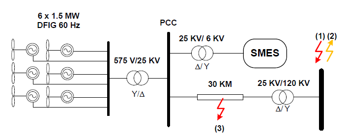
The system under study is shown in Fig. 2. This system consists of six of 1.5 MW DFIG that is connected through a 30 Km distribution line to a grid. A Superconducting Magnetic Energy Storage (SMES) Unit is connected at Point of Common Coupling (PCC) to improve the DFIGs’ Fault Ride Through (FRT) capability. The DFIG itself is based on the typical design as introduced in [8]. The topology of a DFIG, as depicted in Fig. 1, consists of two converters that allow transfer energy from WTG to the grid and vice versa.
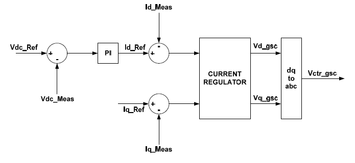
The two converters namely grid side converter (GSC) and rotor side converter (RSC) are linked with a capacitor that is aimed to maintain the desired level of voltage to allow the energy transfer. The typical generic control system that normally applied in a DC link of DFIG is shown in Fig. 3 [8].
SMES Configuration
SMES Unit has been recognized as a promising device to improve power system performance. It has been studied earlier in [9], that SMES could damp the power oscillation during the event of sub-synchronous condition. It also applied for power conditioning of wind energy based power plants [10] and smoothing out the power output of WTG using SMES-FCL [11]. Our prior works in [12, 13, 14, 15], discussed the capability of SMES to improve both the DFIG’s and FCWECS’ fault ride through and effectively avoid it from disconnecting from the grid. However, not much attention is given to study the detailed impact of grid fault level on DC link voltage profile. A few papers present a new concept of controlling the DC link device as presented in [16] and [17]. In [16], a study is focused on introducing a new concept of DC link current controller to reduce the impact of unbalance grid faults and DC currents flow in the capacitor, however it does not discuss any impact of high spike voltage of the DC link. Effort in damping voltage oscillation in DC link is introduced in [17], proposed control with proper selection of filter value is effective in damping the voltage oscillation. However, the control and filter system used seems only for low to middle voltage range and when applied to high DC link voltage, the filters might no longer effective. Moreover, both [16] and [17] are only suitable for new design and construction of a DFIG, whilst connecting a SMES Unit into the PCC is a suitable option for the existing DFIGs-grid connected.
As aforementioned above, when the voltage at DC link violates the safety margin, the internal protection of both converters will block the converters, and consequently, power delivery from DFIG will no longer available. Therefore, it is necessarily important to study the impact of connected SMES on the DC link voltage profile. The control scheme of SMES Unit in this paper is described in Fig. 4 [5].
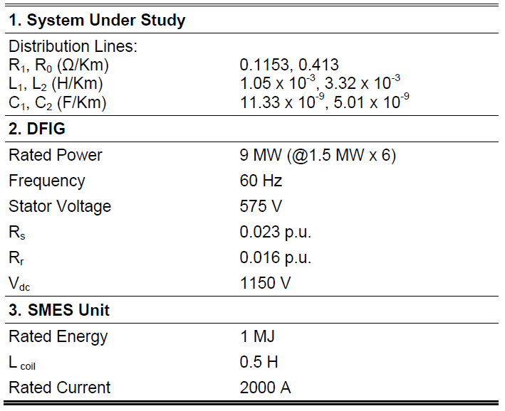
There are two control algorithms are applied in the SMES Unit. To control the energy transfer from the voltage source converter (VSC) to the PCC, a hysteresis current regulator is employed, whereas the energy from the superconductor coil is dictated by a fuzzy logic controller. All parameters including the fuzzy regulation set are referred to [5]. The size and parameters of the overall system including the SMES Unit are provided in Table 1.
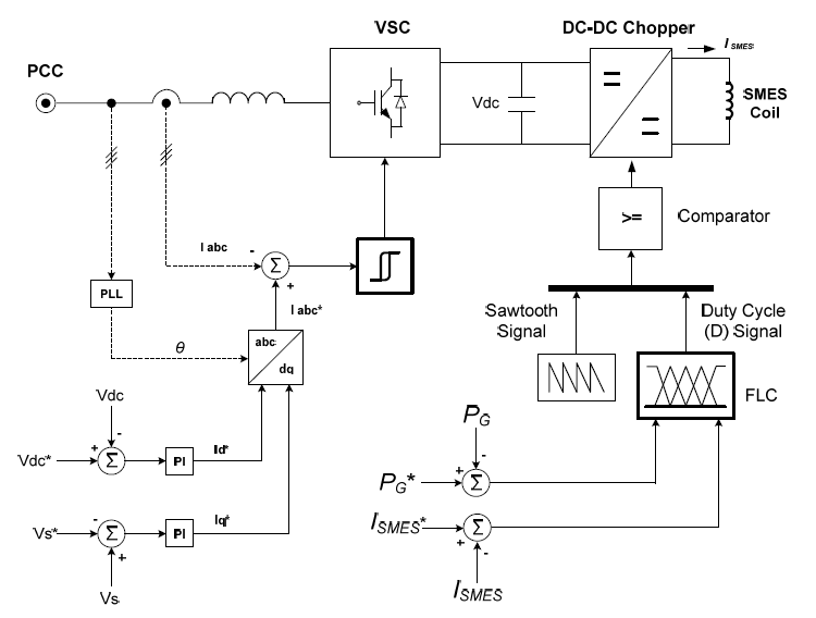
Table 1. Parameters used in the model of System under Study, DFIG and SMES Unit [5]
Simulation Results and Discussion Voltage Sag at the Grid Side
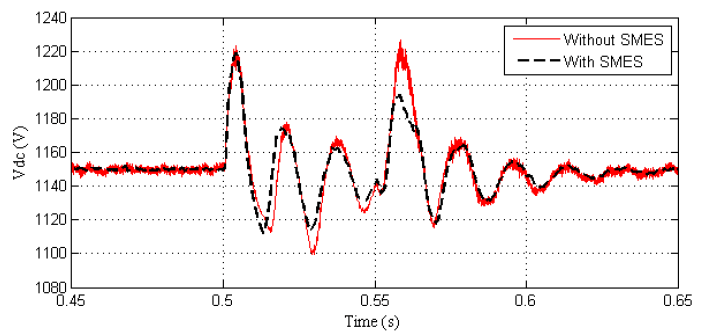
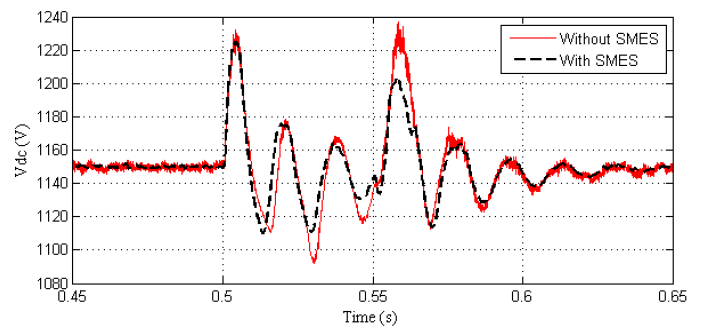
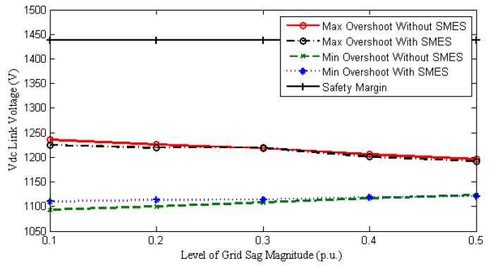
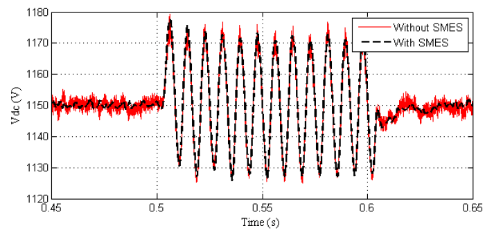
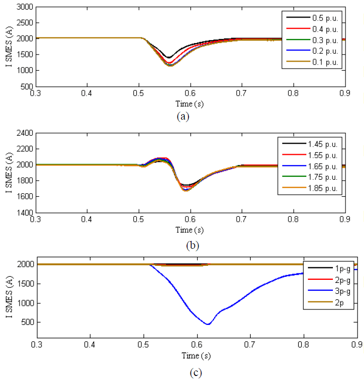
In this type of fault, a certain level of voltage sags’ magnitude was applied at the grid side to examine the impact of the connected SMES on DC link voltage of the DFIG. The magnitude faults level on the grid varies from 0.5 p.u. to 0.1 p.u. and lasting for 0.05s. The simulation results for 0.5 p.u. to 0.1 p.u. are shown in Fig. 5 to Fig. 10. In this case, the lower the magnitude of sag, the higher overshoot voltage occurs in the DC link voltage. With SMES connected at the PCC, overshoot voltage is slightly reduced and no further action required by the protection system in this case as the overshoot is not violated the safety margin level as can be seen in Fig. 10.
Voltage Swell at the Grid Side
Voltage swell, even though scarcely occurs, could damage the power electronics switches in a certain level of a voltage spike. Voltage swell usually occurs when switching off a large load or switching on capacitors banks that causing voltage rise larger than 1.1 p.u. and lasting for 0.5 cycles to 1 minute [18]. When voltage swell occurs suddenly and at a certain level of a voltage spike, it could damage the IGBTs of both GSC and RSC. In this case, a certain level of grid swells is simulated from a magnitude level of 1.45 p.u. to 1.85 p.u. and lasting for 0.05s. The Vdc link voltage responses with and without SMES can be seen in Fig. 11 to Fig. 17.
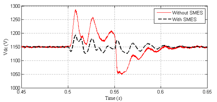
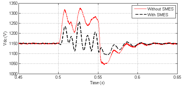
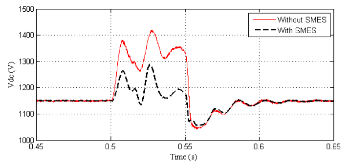
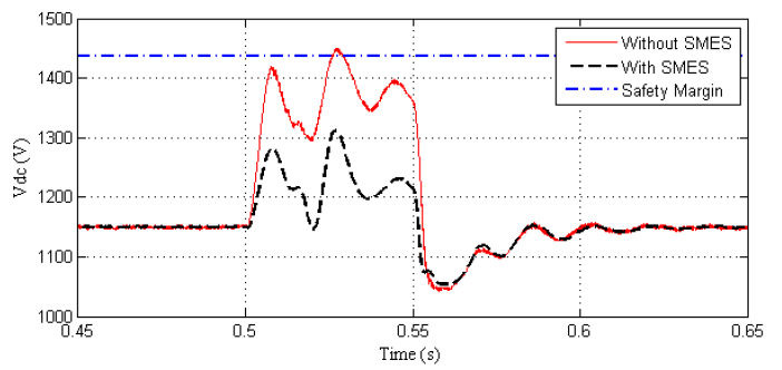
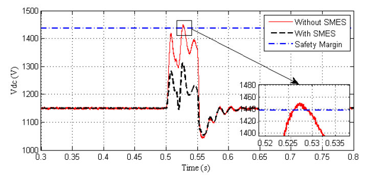
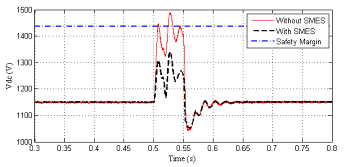
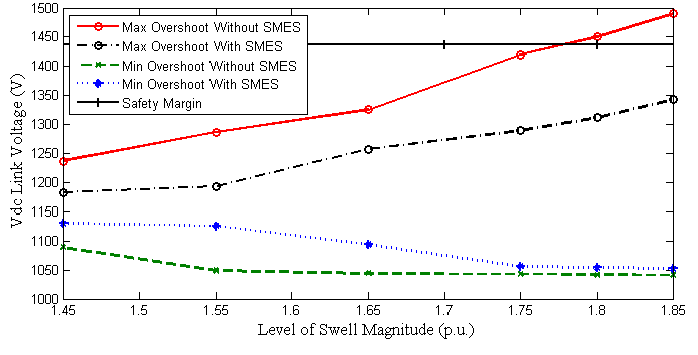
As can be seen from Fig. 11 to Fig. 14, DC link voltages show the increased overshoot voltage when swell magnitude at the grid side increased from 1.45 p.u. to 1.75 p.u., however, the entire maximum overshoots in these levels are tranquil below the maximum safety margin of the allowed voltage in the DC link. In these levels of swell magnitudes, it can be seen that overshoot is significantly reduced when the SMES Unit is connected. If the swell magnitude is further increased to 1.8 p.u., overshoot of DC link voltage is hit over the safety margin as can be seen in Fig. 15 and clearly shown in the zoomed version in Fig. 16. In this case, with proper sensitivity and settling of the protection system, the protection system may operate to avoid the IGBTs damage. It is obviously exhibited in Fig. 17, that when the swell magnitude slightly increased into 1.85 p.u. the overshoot nearly reaches 1500 V or about 5.5% above the safety margin of DC link Voltage. However, when SMES Unit connected at the PCC, overshoot voltage can significantly be reduced and allow the DC link standstill to operating in normal condition. Fig. 18 shows the significant impact of SMES Unit in reducing the overshoot voltage when the grid swell occurs.
Short Circuit at the Middle Line
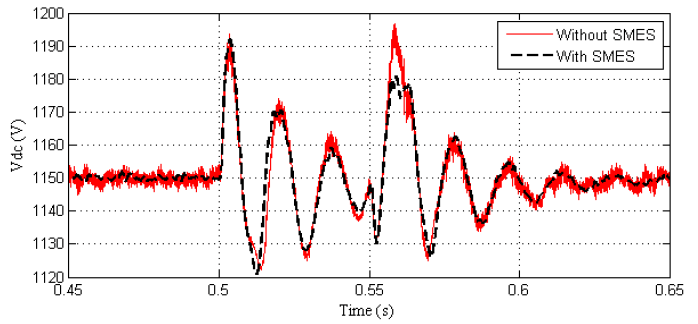
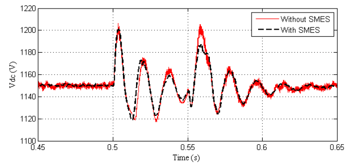
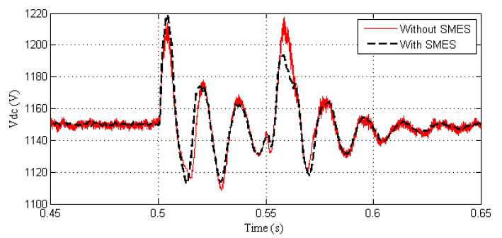
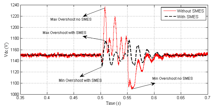
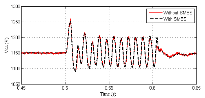
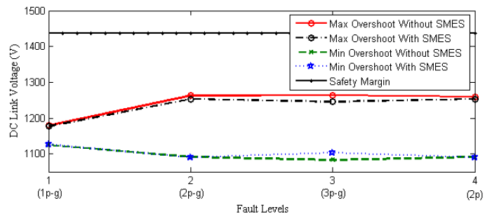
In this case, there are five types of faults were applied; one phase to ground (1p-g); two phase to ground (2p-g); three phase to ground (3p-g); two-phase (2p) and three phase (3p). All these faults are assumed to occur at the middle of the distribution line (15 km). Responses of the DC link voltage with and without SMES are shown in Fig. 19 to Fig. 24.
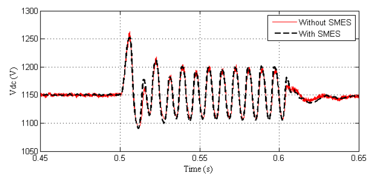
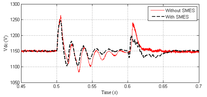
Short circuits are common phenomena in the distribution lines [19]. From the simulation, it can be seen from Fig. 24, that overshoot voltage at DC link increased at 2p-g and 3p-g compared with 1p-g. The trends of 2p and 3p faults are similar to 2p-g and 3p-g respectively. When SMES Unit is connected at the PCC, overshoot voltage at DC link is reduced slightly. Yet, again, these faults are still in the range of safety margin of the DC link voltage, therefore, GSC and RSC are standstills to operate.
Conclusion
Impact of SMES Unit connected with DFIG has been simulated and demonstrated in this paper during various types and fault levels occurrence. It can be concluded that the control algorithm of both VSC and DC-DC Chopper of the SMES could optimally operate during the faults. Impacts of SMES Unit could slightly reduce the overshoot for both grid sag and short circuit events. However, these two fault cases will not damage the switching parts as the voltage safety margin is not violated. Impact of SMES Unit connected to the PCC is significantly shown at the grid swell, particularly when the magnitude of grid swell is increased to 1.8 p.u. Without SMES Unit, the overshoot of DC link voltage increased beyond the safety margin that may cause the DFIGs disconnected from the grid, however when SMES Unit connected to the PCC, the overshoot voltage of DC link significantly reduced about 50% of the overshoot voltage and maintain the DC link voltage below the maximum safety margin voltage that allowed in the DFIG’s DC link part.
Acknowledgment: The first author would like to thank Research, Technology and Higher Education Ministry of Indonesia for supporting the Research.
REFERENCES
[1] C. Vázquez Hernández, T. Telsnig, A. Villalba Pradas, C. Vazquez Hernandez, T. Telsnig, and A. Villalba Pradas, “JRC Wind Energy Status Report 2016 Edition,” 2017.
[2] A. Petersson, T. Thiringer, “Grid Integration of Wind Turbines”, Przeglad Elektrotechniczny, Issue: 5, Pg. 470-475. 2004.
[3] V. Akhmatov, Analysis of dynamic behaviour of electric power systems with large amount of wind power, no. April. 2003.
[4] T. Ackermann, Wind Power in Power System. West Sussex, England: Wiley and Sons, ltd, 2005.
[5] A. M. S. Yunus, M. A. S. Masoum, and A. Abu-Siada, “Application of SMES to enhance the dynamic performance of DFIG during voltage sag and swell,” IEEE Trans. Appl. Supercond., vol. 22, no. 4, 2012.
[6] A. M. Shiddiq Yunus, A. Abu-Siada, and M. A. S. Masoum, “Application of SMES unit to improve DFIG power dispatch and dynamic performance during intermittent misfire and fire through faults,” IEEE Trans. Appl. Supercond., vol. 23, no. 4, 2013.
[7] A. M. Shiddiq Yunus, A. Abu-Siada, and M. A. S. Masoum, “Improving dynamic performance of wind energy conversion systems using fuzzy-based hysteresis current-controlled superconducting magnetic energy storage,” IET Power Electron., vol. 5, no. 8, p. 1305, 2012.
[8] R. Gagnon, G. Turmel, C. Larose, J. Brochu, G. Sybille, and M. Fecteau, “Large-Scale Real-Time Simulation of Wind Power Plants into Hydro-Québec Power System,” 9th Int. Work. Large-Scale Integr. Wind Power into Power Syst. as well as Transm. Networks Offshore Wind Power Plants, 2010.
[9] L. Wang, L. S. Muh, and L. C. Huang, “Damping subsynchronous resonance usinf superconducting magnetic energy storage unit,” IEEE Trans. Energy Convers., vol. 9, no.4, pp. 770–777, 1994.
[10] A. Rodriguez, M. Rizo, E. Bueno, F. J. Rodriguez, A. Garces, and M. Molinas, “Analysis and performance comparison of different power conditioning systems for SMES-based energy systems in wind turbines,” 2012 3rd IEEE Int. Symp. Power Electron. Distrib. Gener. Syst., pp. 527–533, 2012.
[11] I. Ngamroo, “Optimization of SMES-FCL for Augmenting FRT Performance and Smoothing Output Power of,” IEEE Trans. Appl. Supercond., vol. 26, no. 7, 2016.
[12] A. M. Shiddiq Yunus, A. Abu-Siada, and M. A. S. Masoum, “Improvement of LVRT capability of variable speed wind turbine generators using SMES unit,” 2011 IEEE PES Innov. Smart Grid Technol. ISGT Asia 2011 Conf. Smarter Grid Sustain. Afford. Energy Futur., 2011.
[13] A. M. Shiddiq Yunus, A. Abu-Siada, and M. A. S. Masoum, “Application of SMES unit to improve the high-voltage-ridethrough capability of DFIG-grid connected during voltage swell,” 2011 IEEE PES Innov. Smart Grid Technol. ISGT Asia 2011 Conf. Smarter Grid Sustain. Afford. Energy Futur., 2011.
[14] A. M. S. Yunus, A. Abu-Siada, and M. A. S. Masoum, “Effects of SMES on dynamic behaviors of type D-Wind Turbine Generator-Grid connected during short circuit,” IEEE Power Energy Soc. Gen. Meet., pp. 11–16, 2011.
[15] A. M. S. Yunus, A. Abu-Siada, and M. A. S. Masoum, “Effect of SMES unit on the performance of type-4 wind turbine generator during voltage sag,” in IET Conference on Renewable Power Generation (RPG 2011), 2011, pp. 1–4.
[16] C. Liu, D. Xu, N. Zhu, F. Blaabjerg, and M. Chen, “DC-voltage fluctuation elimination through a DC capacitor current control for DFIG converters under unbalanced grid voltage conditions,” IEEE Trans. Power Electron., vol. 28, no. 7, pp.3206–3218, 2013.
[17] S. E. O. Cajethan M. Nwosu, Cosmas U. Ogbuka, “Control model design to limit DC-link voltage during grid fault in a dfig variable speed wind turbine,” J. Electr. Eng., vol. 68, no. 4, pp.274–281, 2017.
[18] E. F. M. Masoum, Power Quality in Power Systems and Electrical Machines. Colorado, USA: Elsevier, 2008.
[19] H. Lund and P. Quinlan, Renewable Energy Systems. 2014.
Authors: Dr. A. M. Shiddiq Yunus is with Energy Conversion Study Program, Mechanical Engineering Department, State Polytechnic of Ujung Pandang, Makassar 90245, Indonesia, Email: shiddiq@poliupg.ac.id;
Dr. Makmur Saini is with Power Generation Engineering Study Program, Mechanical Engineering Department, State Polytechnic of Ujung Pandang, Makassar 90245, Indonesia, Email: makmur.saini@poliupg.ac.id,
Dr. Ahmed Abu-Siada is with Electrical and Computing Engineering Department, Curtin University, Perth 6102, WA, Australia, Email: A.AbuSiada@curtin.edu.au;
Dr. Mohammad A.S., Masoum is with Electrical Engineering at Utah Valley University, Orem UT, 84058, USA, Email: mmasoum@uvu.edu.
Source & Publisher Item Identifier: PRZEGLĄD ELEKTROTECHNICZNY, ISSN 0033-2097, R. 95 NR 8/2019. doi:10.15199/48.2019.08.27
