Published by Jarosław ŁUSZCZ, Politechnika Gdańska, Wydział Elektrotechniki I Automatyki
Abstract. Voltage transformers are widely used in power quality monitoring systems in medium and high voltage grids. This paper presents accuracy problems related to voltage harmonics transfer through instrument transformers. A simplified lumped-parameters wideband circuit model of the voltage transformer is proposed and verified by simulation and experimental investigations. A number of voltage transformers have been tested in the frequency range up to 30 MHz. The obtained results prove that broadband voltage transfer characteristic of the voltage transformer usually exhibits various irregularities, especially in high frequency range, which are related to windings’ parasitic capacitances and cannot be neglected in accuracy analysis.
Streszczenie. Przekładniki napięciowe są powszechnie wykorzystywane do pomiarów parametrów jakości energii elektrycznej w sieciach średnich i wysokich napięć. W artykule przedstawiono problemy związane z dokładnością przenoszenia zniekształconych przebiegów napięć poprzez przekładniki napięciowe. Zaproponowano oraz zweryfikowano symulacyjnie i eksperymentalnie uproszczony szerokopasmowy model obwodowy przekładnika napięciowego. Weryfikację eksperymentalną przeprowadzono dla kilku typowych przekładników napięciowych stosowanych w sieciach średnich napięć w zakresie częstotliwości do 30 MHz. Przeprowadzone badania potwierdziły występowanie istotnych nieregularności charakterystyki częstotliwościowej przenoszenia związanych z wpływem pojemności pasożytniczych uzwojeń, które nie mogą być pomijane przy określaniu dokładności pomiarów. (Transformacja zniekształceń harmonicznych napięcia w przekładnikach napięciowych średnich napięć)
Keywords: voltage transformers, power quality, voltage harmonic distortions, overvoltages.
Słowa kluczowe: przekładniki napięciowe, jakość energii, zniekształcenia harmoniczne napięcia, przepięcia.
Introduction
Voltage harmonic distortion level is one of the significant parameters of power quality in power system. Voltage distortion assessments, especially in medium voltage (MV) and high voltage (HV) grids, are usually based on measurements in which voltage transformers are commonly used. The transfer ratio of a voltage transformer fed by distorted primary voltage with harmonic components can be significantly different for frequencies higher then fundamental. During the last decades major problems related to voltage distortions have been usually encountered in frequency range up to 40th harmonic, mostly in LV grids. Nowadays, due to the evident increase of the overall power of nonlinear loads connected to grid and higher modulation frequencies widely used, distorted voltage propagates deeply into MV grids and goes evidently above frequency band of 2 kHz.
Classic circuit model of voltage transformer
VTs are mostly used in MV and HV systems for separation of the measuring and protecting circuits from high voltage hazard. Rated primary voltages of VTs, typically used in power system, have to correspond to rated voltages of MV and HV transmission. Secondary rated voltage levels usually used in typical measuring and protection systems are: 100 V, 100/3 V, 100/√3 V which results with transformation ratios of the order from a few tenth up to few hundreds for MV VT and more than a thousand for HV VT. Such a high transformation ratio and low rated power of VT has significant influence on its specific parameters, especially related to performance in wide frequency range.
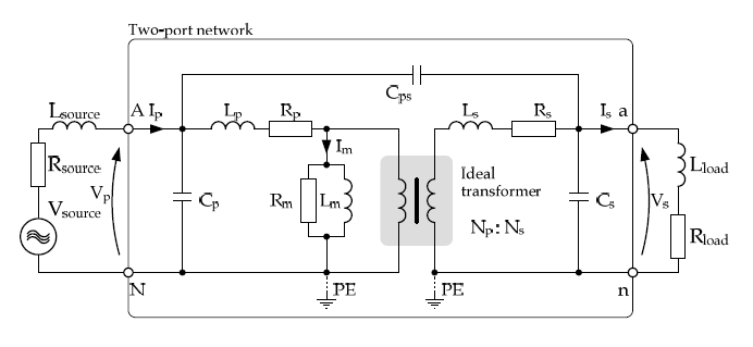
The classic equivalent circuit model of two windings transformer usually used for modelling VT for power frequency is presented in Fig.1. This model consists of leakage inductances of primary winding Lp and secondary winding Ls and magnetizing inductance Lm. Corresponding resistances represent VT losses in magnetic core Rm and windings Rp, Rs. Based on these parameters frequency dependant transfer characteristic for frequencies higher than the nominal (50 or 60 Hz) can be estimated. Theoretical wideband transfer characteristic of VT modelled by using classic circuit model is presented in Fig.1 where low corner frequency of pass band flow and high corner frequency of pass band fhigh can be defined based on 3 dB transfer ratio decrease margin assumption. Low and high frequency response of VT can be determined analytically based on VT classic circuit model parameters according to formula (1) and (2).
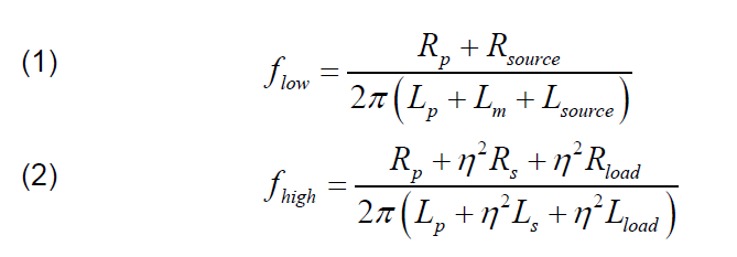
Concluding, low frequency response of VT is mostly dependant on ratio of leakage to magnetizing impedance which limits transfer characteristic in low frequency range, while high frequency response depends mainly on sum of leakage and load impedances.
Modelling of VT in high frequency range
Modelling of VT in a HF range using classic circuit model is usually not adequate enough because of existence of parasitic capacitances of windings and frequency dependant grid impedance and VT load impedance. Parasitic capacitances of VT windings are usually unwelcome and unluckily unavoidable; there are only various techniques used to reduce its values and distribution. Consequences of parasitic capacitances are especially significant for multilayer windings with high number of turns which is characteristic for high voltage and low power transformers like VT.
Identification of distributed partial parasitic capacitances for particular VT requires detailed specification of winding arrangement is extremely elaborative and usually does not provide adequate enough results. Difficulties of parasitic capacitances identification can be reduced by defining lumped equivalent capacitances which represent groups of partial capacitances related to entire winding or part of windings; for example single layer of winding. Lumped representation of parasitic capacitances allows reducing winding model complexity and consequently simplifies noticeably its parameters identification process. Winding model simplification level, which is possible to apply, should be closely correlated with the expected adequacy in a given frequency range and depends evidently on particular winding arrangement complexity. Commonly, three methods of winding parasitic capacitances circuit representations are used to model transformer windings:
• winding terminals related – where all defined lumped equivalent capacitances are connected to windings’ terminals only,
• partially distributed – lumped parasitic capacitances are specified for most representative internal parts of winding, like for example windings layers, winding shields,
• fully distributed – windings are modelled as a series and parallel combination of inductances and capacitances which form ladder circuit with irregular parameter distribution.
Generally, more detailed parasitic capacitance representation allows obtaining higher accuracy in wider frequency range. Nevertheless, the model complexity should be kept within reasonable limits to allow achieving higher usefulness because of parameters identification process simplification.
Identification of VT parameters in wide frequency range
Voltage transformation ratio of VT in wide frequency rage is closely related to impedance – frequency characteristics of primary and secondary windings. Therefore, measurement results of VT magnetizing and leakage impedances within the investigated frequency range are the fundamental data resources for analysis its broadband behaviour and allow estimating circuit model parameters. Measurement of VT impedances can be done similarly to a typical no load and short circuit tests recommended for power frequency with use of sweep frequency excitation.
Distributed parasitic capacitances of VT windings are modelled by the lumped capacitances related to windings terminals only (Fig. 3). This assumption reduces noticeable model complexity and allows determining parasitic capacitances based on the measured windings impedances. In the analysed case primary and secondary windings of the investigated VT are one side grounded which limits furthermore the number of lumped capacitances necessary to be determined.
Detailed analysis of VT magnetizing and leakage impedance-frequency characteristics and identification of specific resonance frequencies allows estimating parameters of the VT circuit model presented in Fig. 3. The method of determination parasitic lumped capacitances is based on identification of resonance frequencies which are usually possible to determine by using the measured impedance characteristics [5].
Simulation examination of VT broadband circuit model
The investigated circuit model of a VT can be examined by simulation in any PSpice compatible environment in the conducted disturbance propagation frequency range up to 30 MHz. The essential verification of VT model adequacy has been done by determining magnetizing and leakage impedance characteristics which allows verifying model representation adequacy of magnetic coupling between windings.
The developed VT circuit model can be used for simulation analysis of the influence of the VT parameters and its load on the voltage transfer ratio frequency characteristic. The exemplary simulation results of VT voltage transfer ratio characteristics calculated for different resistive loads are presented in Fig. 3. It can be noticed that the VT voltage transfer characteristic change essentially for frequencies higher than the main resonance frequency observed on the leakage impedance, which is about 100 kHz for the evaluated case. Above this frequency VT voltage transfer ratio depends mainly on winding parasitic capacitances and magnetic coupling between windings becomes less meaningful.
Simulation results demonstrate that in frequency range close to leakage impedance resonance VT load has the major influence on the VT transfer characteristic. Increase of resistive VT load reduces significantly VT voltage transfer ratio around this frequency. Obtained simulation results confirm that VT load has significant influence on VT performance in HF range.
Experimental tests of VT transfer characteristic
Experimental investigations have been done for voltage transformers typically used in MV power system with primary and secondary windings grounded. Presented exemplary measurement results have been obtained for VT of 50 VA rated power and 20 kV/0.1 kV nominal transformation ratio. Parameters of the proposed VT circuit model for simulation have been identified by analysis of secondary windings impedance-frequency characteristics measured for no load and short circuit configuration. Measurements have been done in frequency range from 10 Hz up to 30 MHz, which is a range typically used for the analysis of conducted disturbances in power system. Particular attention has been paid to the frequency range below 10 kHz which is obligatory for power quality analysis, especially for analysis of power system voltage harmonics related phenomena.
Accurateness of voltage transfer characteristics (magnitude and phase) of VT is a fundamental aspect for identification and measurement of power quality related events in power system. For the investigated VT the voltage transfer ratio and voltage phase shift characteristics have been measured to reveal measurement accuracy problems of power quality assessment in MV systems. Magnitudes versus phase transfer characteristic of VT measured for frequency range typically used in power quality measurement systems (up to 9 kHz) are presented in Fig. 4.
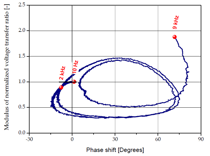
Experimental investigations prove that magnitude and phase errors increase noticeably with frequency. In frequency range up to 2 kHz, the highest magnitude error of about 11 % and phase shift error almost 8o, have been obtained for frequency of 2 kHz. These results confirm that voltage harmonics measurement in MV grids by using VT can be not accurate enough in applications with noticeable harmonic content above approximately 1 kHz.
Magnitudes and phase inaccuracy of VT obtained in frequency range from 2 kHz up to 9 kHz are evidently larger and its frequency dependence is more complex, therefore more difficult to model using simplified circuit models. Magnitude errors in this frequency range reach almost 180% and phase shift error almost 80o, which cannot be accepted in power quality measurement applications.
Conclusions
The main problems with accurate modelling using circuit models are related to windings’ parasitic capacitances and especially identification of its unequal distribution along windings. In order to model the influence of parasitic capacitive couplings existing in a typical VT several simplifications should be considered. The method of VT parasitic capacitances analysis based on the lumped representation is often used and particularly rational, nevertheless, it limits the frequency range within which acceptable accuracy can be obtained.
Parameters of simplified circuit model can be determined based on wideband measurement of leakage and magnetizing impedances. Unfortunately such model can be successfully used only in the limited frequency range. For typical VT used in MV grids the uniform part of transfer characteristic can be obtained usually only up to a few kHz. Above this frequency VT usually exhibits a number of resonances which change evidently its transfer characteristic and cannot be expressed adequately by simplified circuit models. Wideband performance of VT in a particular application is also noticeably related to its load level and character (inductive or capacitive).
The use of VT in power quality monitoring systems in MV grids influences essentially measurement accuracy finally obtained. In power quality measurement applications where dominating harmonics emission is expected only in frequency range below 2 kHz VTs can provide sufficient accuracy in many applications, nevertheless its voltage transfer characteristic should be carefully verified with taking into account particular operating conditions. In the contemporary power grids, harmonics emission spectrum injected to the power system can be much wider than up to 2 kHz, especially by contemporary high power electronic applications. In the frequency range from 2 kHz up to 9 kHz, which is already well specified by harmonic emission standards, use of typical VT is not reliable enough. Measurement errors in frequency range up to 9 kHz are usually not acceptable, because of resonance effects which commonly appear and are difficult to predict.
REFERENCES
[1] Islam, S.M.; Coates, K.M.; Ledwich, G.; Identification of high frequency transformer equivalent circuit using Matlab from frequency domain data. Thirty-Second IAS Annual Meeting, IAS ’97., Conference Record of the 1997 IEEE Industry Applications Conference, 1997.
[2] Kaczmarek, M.; Nowicz, R.; Application of instrument transformers in power quality assessment. MEPS’10 Modern Electric Power Systems Symposium 2010, Page(s): 1 – 5.
[3] Kadar, L.; Hacksel, P.; Wikston, J.; The effect of current and voltage transformers accuracy on harmonic measurements in electric arc furnaces., IEEE Transactions on Industry Applications, Volume 33, Issue 3, May-June 1997 Page(s):780 – 783.
[4] Klatt, M.; Meyer, J.; Elst, M.; Schegner, P.; Frequency Responses of MV voltage transformers in the range of 50 Hz to 10 kHz. 14th International Conference on Harmonics and Quality of Power (ICHQP), 2010.
[5] Łuszcz J.; Iron Core Inductor High Frequency Circuit Model for EMC Application. Coil Winding International & Electrical Insulation Magazine. Volume 28, Issue 1, 2004.
[6] Mahesh, G.; George, B.; Jayashankar, V.; Kumar, V.J.; Instrument transformer performance under distorted-conditions. India Annual Conference, 2004. Proceedings of the IEEE INDICON 2004. Page(s): 468 – 471.
[7] Shibuya, Y.; Fujita, S.; High frequency model and transient response of transformer windings, Transmission and Distribution Conference 2002: 6-10 Oct. 2002
[8] Vermeulen, H.J.; Dann, L.R.; van Rooijen, J.; Equivalent circuit modelling of a capacitive voltage transformer for power system harmonic frequencies, IEEE Transactions on Power Delivery, Volume 10, Issue 4, Oct. 1995.
[9] Yao Xiao; Jun Fu; Bin Hu; Xiaoping Li; Chunnian Deng; Problems of voltage transducer in harmonic measurement., IEEE Transactions on Power Delivery, Volume 19, Issue 3, July 2004 Page(s):1483 – 1487.
Authors: dr inż. Jarosław Łuszcz, Gdansk University of Technology, Faculty of Electrical and Control Engineering ul. Sobieskiego 7, 80-216 Gdańsk, E-mail: jlusz@ely.pg.gda.pl
Source & Publisher Item Identifier: PRZEGLĄD ELEKTROTECHNICZNY (Electrical Review), ISSN 0033-2097, R. 88 NR 8/2012
