Published by Electrotek Concepts, Inc., PQSoft Case Study: Effect of Synchronous Closing Control on Capacitor Energizing Transients, Document ID: PQS0903, Date: October 15, 2009.
Abstract: The application of utility capacitor banks has long been accepted as a necessary step in the efficient design of utility power systems. In addition, capacitor switching is generally considered a normal operation for a utility system and the transients associated with these operations are generally not a problem for utility equipment. These low frequency transients, however, can cause problems for low voltage power electronic-based loads.
Adjustable-speed drives are susceptible to dc link overvoltage trips caused by utility capacitor switching. In general, an increase in input inductance (choke or isolation transformer) will reduce the possibility of nuisance tripping. However, if the customer has power factor correction capacitors on the same bus, it may be necessary to take additional remedial actions. This case study investigates the potential for voltage magnification and nuisance tripping during utility capacitor bank switching on a 24kV distribution system.
INTRODUCTION AND MODEL DEVELOPMENT
Transient overvoltages and nuisance tripping of a customer’s adjustable-speed drive during utility capacitor bank switching was studied for the system shown in Figure 1. The case involved determining overvoltage transients during uncontrolled capacitor bank switching as well as an evaluation of the effectiveness of synchronous closing control. The accuracy of the system model was verified using three-phase and single-line-to-ground fault currents and other steady-state quantities, such as capacitor bank rated current and voltage rise.
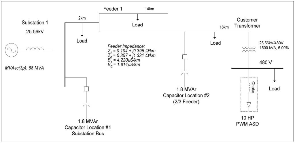
A typical 10 hp customer adjustable-speed drive was included in the simulation model to determine the potential for nuisance tripping of the drive when a 1.8 MVAr, 25.56kV capacitor bank is switched at either the substation bus or at a location that is 2/3 of the feeder length. The energizing frequency for the 1.8 MVAr, 25.56kV distribution capacitor bank with a source strength of 68 MVA may be approximated using the following expression:

The steady-state voltage rise for this case may be approximated using the following expression:
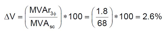
A maximum voltage rise design limit of 3% would mean that the largest capacitor bank that can be switched at the substation for the studied circuit would be approximately 2 MVAr. Installation of a larger substation capacitor bank, such as 6 MVAr, would result in an excessive steady-state voltage rise (8.8%) and would likely require a circuit reconfiguration.
SIMULATION RESULTS
The effectiveness of synchronous closing control on the capacitor bank switch was evaluated in a series of cases that varied the timing error from an ideal voltage zero closing. Synchronous closing is independent contact closing of each phase near a voltage zero. Previous analysis has indicated that a closing consistency of ±1.0msec provides overvoltage control comparable to properly rated pre-insertion resistors. The success of a synchronous closing scheme is often determined by the ability to repeat the process under various (system and climate) conditions.
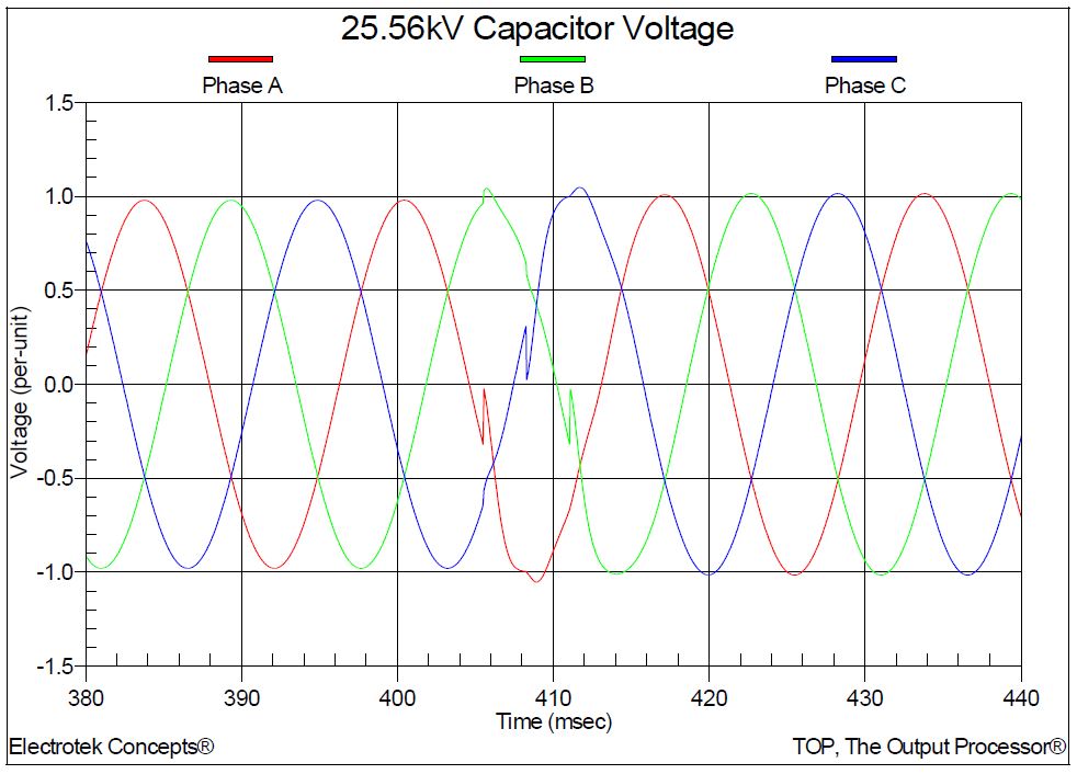
Simulation results are summarized in Table 1. The maximum transient overvoltage (refer to Figure 2) at the 25.56kV bus when energizing the 1.8 MVAr capacitor bank at the substation bus was 1.26 per-unit. Typical overvoltage magnitude levels range from 1.1 to 1.5 per-unit for smaller substation and feeder capacitor banks. The maximum transient overvoltage (refer to Figure 3) at the customer’s 480V bus was 1.09 per-unit. The resulting dc voltage on the 10 hp adjustable-speed drive in the customer facility was 665 volts (refer to Figure 4) which is lower than the assumed trip level of 780 volts, so it is assumed that the drive will not trip for this case.
Table 1 – Summary of Simulation Results for Synchronous Closing Evaluation


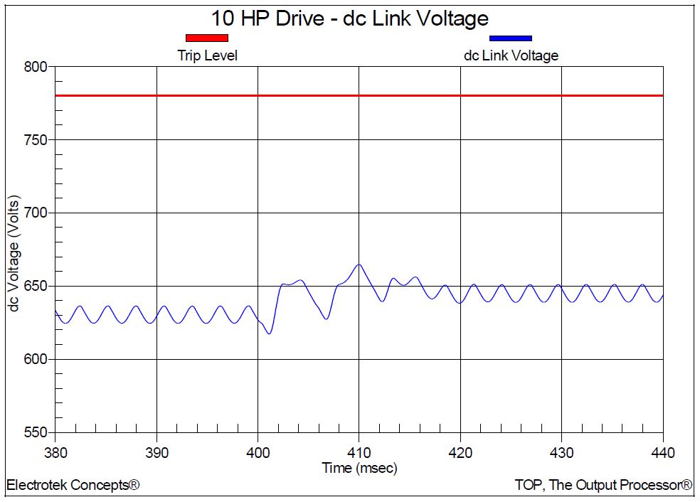
Figure 5 shows the resulting 25.56kV bus voltage for the worst-case synchronous closing control case with a +1.0msec error. The maximum transient overvoltage is reduced from 1.26 per-unit to 1.03 per-unit. The customer’s 480 volt bus voltage is reduced from 1.09 per-unit to 1.01 per-unit and the dc voltage on the 10 hp adjustable-speed drive is reduced from 665 volts to 632 volts. The maximum transient overvoltage (refer to Figure 6) at the 25.56kV feeder location when energizing the 1.8 MVAr capacitor bank at 2/3 of the feeder length was 1.32 per-unit. The maximum transient overvoltage at the customer’s 480V bus was 1.18 per-unit. The resulting dc voltage on the 10 hp adjustable-speed drive in the customer facility was 699 volts, which is lower than the assumed trip level of 780 volts, so it is assumed that the drive will not trip for this case.


Figure 7 shows the resulting 25.56kV feeder voltage for the worst-case synchronous closing control case with a +1.0msec error. The maximum transient overvoltage is reduced from 1.32 per-unit to 1.05 per-unit. The customer’s 480 volt bus voltage is reduced from 1.18 per-unit to 1.03 per-unit and the dc voltage on the 10 hp adjustable-speed drive is reduced from 699 volts to 661 volts.
SUMMARY
Observations and conclusions for this case study include:
1.The devices and equipment being applied on the power system are more sensitive to power quality variations than equipment applied in the past. New equipment includes microprocessor-based controls and power-electronic devices that are sensitive to many types of disturbances. Controls can be affected, resulting in nuisance tripping or misoperation as part of an important process, or actual device failure can occur.
2.Capacitor bank switch selection and configuration will generally depend on switch capabilities (e.g., short circuit interrupting and capacitance switching ratings), mitigation device selection (e.g., pre-insertion vs. synchronous closing), site considerations, and an economic evaluation.
3.Transient overvoltages at the substation bus and feeder capacitor bank location when energizing the 1.8 MVAr capacitor bank were 1.26 per-unit and 1.32 per-unit respectively. These values are well below arrester protective levels for the simulated system and the simulated adjustable-speed drive did not trip for both cases without and with synchronous closing control.
4.Transient overvoltages associated with energization of the 25.56kV capacitor bank can be reduced with the application of synchronous closing control. The resulting overvoltages at the substation bus and feeder capacitor bank location were 1.03 per-unit and 1.05 per-unit respectively. In addition, the resulting overvoltages at customer’s 480 volt bus were also reduced, thereby significantly reducing the probability of localized customer problems due to sensitive equipment or low voltage power factor correction.
5.For the studied system, it is unlikely that the energization of a 1.8 MVAr capacitor bank at either the substation bus or feeder location will create transient overvoltages severe enough to cause problems for customer systems.
REFERENCES
G. Hensley, T. Singh, M. Samotyj, M. McGranaghan, and T. Grebe, Impact of Utility Switched Capacitors on Customer Systems Part II – Adjustable Speed Drive Concerns, IEEE Transactions PWRD, pp. 1623-1628, October, 1991.
G. Hensley, T. Singh, M. Samotyj, M. McGranaghan, and R. Zavadil, Impact of Utility Switched Capacitors on Customer Systems – Magnification at Low Voltage Capacitors, IEEE Transactions PWRD, pp. 862-868, April, 1992.
Electrotek Concepts, Inc., Evaluation of Distribution Capacitor Switching Concerns, Final Report, EPRI TR-107332, October 1997.
RELATED STANDARDS
IEEE Std. 1036-1992
GLOSSARY AND ACRONYMS
ASD: Adjustable-Speed Drive
PWM: Pulse Width Modulation
MOV: Metal Oxide Varistor
TVSS: Transient Voltage Surge Suppress
