Published by
- Jan Meyer, Robert Stiegler, Matthias Klatt, Technische Universitaet Dresden, Germany (Jan.Meyer@tu-dresden.de)
- Micheal Elst, RITZ Instrument Transformers GmbH, Germany (Michael.Elst@ritz-international.com)
- Erik Sperling, PFIFFNER Instrument Transformer Ltd. Switzerland (Erik.Sperling@pwm.ch)
21st International Conference on Electricity Distribution, Frankfurt, 6-9 June 2011 (Paper 0917)
Abstract
The measurement of harmonic currents and voltages is a key issue e.g. for the assessment of voltage quality or the compliance verification for generating installations. Except for voltage measurements in LV networks the adaption of the primary signal to the input ranges of the power quality instrument needs instrument transformers. The accuracy of these transformers above the nominal frequency is usually not known and not defined by the appropriate standards up to now.
The main intention of the paper is to present the accuracy of conventional instrument transformers at higher frequencies for voltage levels up to 330kV and to attract attention of network operators, equipment manufacturers and regulators to possible influences on the harmonic measurements.
A short introduction is followed by a description of the measurement system and methodology. Next the measurements of the frequency dependent transformer ratio and frequency dependent phase angle difference for about 100 voltage transformers (VTs) are discussed in detail. For all analyses the frequency ranges from 50Hz up to 5kHz is considered. A final summary of the results should give first guidance to all interested parties on how to treat with voltage harmonic measurement accuracy in MV, HV and EHV networks.
Introduction
The number of sources of low as well as high order harmonics in distribution and transmission grids increases continuously (e.g. wind parks, HVDC links, …). It is very important that all involved parties know the current situation on the system. Hence network operators, customers and regulators carry out more and more power quality measurements including harmonics in all voltage levels from LV to EHV. IEC 61000-4-30 defines methods
and accuracies for the measurement instruments itself, but explicitly excludes the accuracy of instrument transformers. It is therefore not possible to specify an overall accuracy for such harmonic measurements. First research of the authors was focused on the frequency dependent behavior of instrument transformer ratio for MV voltage transformers [1]. A few publications exist for VTs for higher voltage levels [e.g. 2]. The factors with influence to the frequency behavior of instrument transformers, namely VTs, are detailed discussed in [1]. In general, these influences can be divided into 3 categories:
1. construction-specific (e.g. rated primary value)
2. operational-specific (e.g. burden)
3. test signal-specific (e.g. test-waveform)
The construction-specific characteristics have the most significant influence on the frequency behavior of VTs. It mainly defines the capacitances and inductances, which are responsible for the resonance effects within the instrument transformer. The following design-specific characteristics are discussed and analyzed in the paper:
1. voltage level
2. basic design (cast resin, gas insulated, or oil insulated, capacitive)
3. single or combined transformer
It should be pointed out that VTs with nearly same properties may still vary in their frequency characteristics due to different designs of constructions, housings and other parameters, like rated power or number of secondary windings. Due to its importance for power quality assessment according to standards and it’s more critical behavior the paper is focused on VTs (single-pole). First results for MVCTs and HV-CTs show no significant resonance effects in the frequency range up to 5 kHz.
Measurement System
In conclusion of the results from former research the measurement system was adapted to handle not only MVVTs but also VTs built for voltage levels up to 400 kV. Several test setups where discussed in [1]. For an extensive test setup a multi-frequent test signal consisting of a fundamental sine component at rated primary voltage and a second, swept sine component of smaller amplitude was used. A simplified setup using only a swept single frequent sine of small amplitude showed only insignificant differences compared to the extensive setup (cf. to [1] for more details). Therefore the simplified setup as shown in Fig. 1 is used for the measurements. Its main advantage compared to the extensive setup is its mobility, which was mandatory for the project, especially for the measurement of HV and EHV voltage transformers. The test signal is provided by a single-phase voltage source at voltages up to 280V (RMS) and frequencies up to 5 kHz. The voltage source is controlled by an external signal generator. For data acquisition an ADC-board with simultaneous sampling channels at sampling rates up to 2MS/s is used.

Basic schema of measurement system.
Figure 1
Measurement Methodology
As mentioned before a single-frequent sweep of sine signals of different frequency is used for the measurements. Each sweep starts at a predefined frequency. The frequency is stepwise increased up to 5 kHz. The step size changes adaptively. By this adaptive step control even small resonances are measured with a sufficient frequency resolution while measurement time is optimized (about 2-3 minutes per VT). Minimum step size is 5Hz. For each frequency primary voltage Upri (green plot in Fig.2) and secondary voltage Usec (red plot in Fig. 2) are measured simultaneously. Finally, the normalized transformer ratio is calculated (blue plot in Fig. 2) that allows better comparison between different transformers:

The calculation of the phase angle difference is based on the following equation:

ϕpri is always 0° due to the synchronization of the measurement to the positive zero crossing of primary voltage Upri.

Figure 2
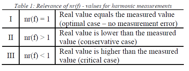
Depending on the value of the ratio nr(f) three different ranges (I, II, III – cf. Fig. 2) have to be distinguished.
Evaluation Methodology
Fig. 3 shows the plots of normalized ratio nr(f) for 3 different VTs, namely a 66-kV-VT (green), a 110-kV combined transformer (blue) and a 220-kV-VT (red). All VTs are inductive, oil-paper insulated and for outdoor use. Fig. 4 shows the corresponding phase angle difference Δϕ(f) respectively. All measurements were carried out without burden. Based on the figures the behavior of frequency dependency can be discussed in more detail:
1. Resonance frequency and resonant rise of the first resonance differ significantly due to the diverse design of VTs.
2. For frequencies higher than the first resonance accurate measurements are very difficult. A correction based on the transfer characteristic is not easily possible due to the high sensitivity of the characteristic in this range from lots of influencing factors (cf. [1]).
3. Characterizing the frequency response of a VT based on the resonance frequency only is not sufficient, because deviation from rated transformer ratio at nominal frequency starts usually at much lower frequencies.
4. Depending on the design the first resonance can be a parallel one (Maximum) or a series one (Minimum). Therefore both cases (conservative or critical) according to Tab. 1 may be possible below the first resonance.
5. Large phase angle differences are always related to the resonances. The higher the resonant rise, the higher the phase angle difference. For narrow resonances with high resonance rise (larger than 3) the phase angle difference can significantly exceed 90°.
6. For resonance conditions where a maximum is followed by a minimum (case II acc. to Tab. 1) phase angle difference becomes positive. If minimum is followed by a maximum, the phase angle difference becomes negative.

Figure 3

Figure 4
As an appropriate way to quantify the accuracy of a VT the paper uses different thresholds for transformer ratio accuracy and phase angle accuracy.

For each of the thresholds the corresponding critical frequency (fcrit) is calculated. In order to compensate possible differences that may result from the low excitation, in this paper the difference |nr(f)-nr(fN)| is related to the measured ratio at nominal frequency instead of the rated (name plate) transformer ratio. Fig. 5 shows exemplarily the plot of transformer ratio accuracy Δnr(f) with marked thresholds.

Figure 5
Measurement Results
The critical frequencies fcrit for transformer ratio accuracy Δnr(f) = 1 % are shown in Fig. 6. While rated primary voltage can be read from the figure directly, the different design of the transformer is highlighted by a symbol acc. to table 3.


Figure 6
a) Main general findings:
1. The critical frequency up to the point where accurate measurements are possible decreases with voltage level.
2. Even for VTs with same primary voltage the critical frequency fcrit can vary in wide ranges due to the different design. The specification of a single fcrit only per voltage level is not adequate.
b) Some specific findings:
1. Block-design VTs (+) are usually used up to 35kV. The critical frequency varies in a wide range from fcrit ≈ 3500Hz for 10-kV-VTs down to fcrit ≈ 600Hz for 35-kV-VTs.
2. The accuracy of capacitive VTs (*) is guaranteed within a very small frequency range around the nominal frequency only. These VTs are not suitable for harmonic measurements in standard cases.
3. For 66-kV-GIS VTs () the critical frequency is about 500Hz higher compared to the inductive outdoor VTs (O) of same voltage level.
4. 110-kV combined transformers (x) show in most cases a better performance compared to the inductive outdoor VTs (O) for same voltage level.
5. No significant difference exists between inductive outdoor type (O) for 110kV and 220kV. Both are suitable for measurements up to the fcrit ≈ 500Hz (10th harmonic).
In the new 3rd edition of EN 50160 (ratified in 03/2010) the application range is extended from MV networks (Un ≤ 35 kV) to HV networks (Un ≤ 150 kV). Fig. 6 shows that harmonics up to the 25th order can be measured with sufficient accuracy in MV networks up to 20 kV. Only THD accuracy may fail under certain circumstances. Fig. 7 shows that the situation is much more difficult for HV networks. Only the 66-kV-GIS-VTs fulfill all requirements acc. to EN 50160 at a 1-%-transformer ratio accuracy. Measurements in 110-kV-networks may already have an unacceptable error at 9th harmonic. With 110-kVcombined transformers in most cases the error doesn’t exceed 5%. Most international standards related to harmonics in MV, HV and EHV networks (e.g. IEC 61000-3-6 or IEC 61000-2-12) cover the frequency range up to 2.5kHz (50th harmonic) for individual harmonics as well as THD. This requirement is also included in Fig. 7. Fig. 8 shows the transformer ratio accuracy and phase angle accuracy for all analyzed 110-kV-VTs in one diagram. For the chosen phase angle accuracy thresholds the critical frequency fcrit for the transformer ratio accuracy is in virtually all cases lower than fcrit for phase angle accuracy. This means if a certain VT has transformer ratio accuracy better than 1 % its phase angle accuracy is always better than 1° and so on.

Figure 7

Figure 8
Conclusion
The paper is a contribution to the discussion on the accuracy of harmonic measurements using standard VTs, especially at higher voltage levels. It should be defined reasonable accuracy classes for HV and EHV voltage transformers. The influence of transformer ratio accuracy on the harmonic measurements according to actual standards (e.g. EN 50160) was verified. It shows that attention has to be taken to the interpretation of such measurements, especially at voltage levels above 20kV. This is of special importance if regulatory rules should be introduced in future dealing with harmonics. Only instrument transformers of two different manufacturers were analyzed in the project. Due to the high sensitivity of the frequency dependent behavior from transformer design the results may be different to other manufacturers.
Finally, the paper should give impulses for the ongoing standardization work. Adding requirements for frequency dependent behavior of instrument transformers to future standards can improve the quality of harmonic measurements significantly in long-term. As short-term solution for the network distributors that carry out measurements in HV and EHV networks at least the frequency dependent transformer ratio of the used VTs should be known.
Reference
[1] M. Klatt, J. Meyer, M. Elst, P. Schegner, 2010, “Frequency Responses of MV voltage transformers in the range of 50 Hz to 10 kHz”, International Conference on Harmonics and Quality of Power (ICHQP), IEEE, Bergamo (Italy) [2] H. Seljeseth, E.A. Saethre, T. Ohnstad, I. Lien, 1998, “Voltage transformer frequency response. Measuring harmonics in Norwegian 300kV and 132kV power systems” Proceedings 8th International Conference on Harmonics and Quality of Power, p. 820 – 824, vol. 2.

Very informative paper. So for 60Hz, 13.8kV rated systems with inductive type VTs, up to what harmonic order (approximately)should considered in terms of accuracy ?
LikeLike
Hello Rakan, Good question and in typical engineering fashion, that depends. 🙂
Accuracy of ? the turns ratio? or the accuracy of phase angle? Remember this paper is about PT’s we’ll be posting another presentation on CT’s which is more important for power and power flow at harmonic frequencys.
The turns ratio accuracy begins to deteriorate (1%) at 400 to 600 hertz and remember the loses are not linear.
It’s important to note, the physical construction of the PT’s impacts the accuracy as frequencies go up. So if you need a reliable accuracy /frequency profile , you’ll need to contact the manufacturer with exact model # .
You’ll note in this paper the higher the voltage the greater the impact on Frequency response. In my experience lower voltage transformers (<22KV) are fairly linear up to 2 KHZ. (about 30 th harmonic) but remember for most situation the actual voltage RMS of frequencies at that frequency are very small so over all accuracy is questionable.
Regards. TerryC@powerquality.co.th if there are further questions.
LikeLike