Published by 1. Kheira BELHACEL1, 2. Mohamed BOUDIAF2, 3. Mohamed MOUDJAHED3, 4. Abderrahmane BERKANI4, L2GEGI Laboratory, Electrical Engineering Department, Ibn Khaldoun University, Tiaret, Algeria (1, 3, 4). LAADI Laboratory, Electrical Engineering Department, ZIANE Achour University, Djelfa, Algeria (2)
Abstract. Currently and in the last few years, the subject of integrating FACTS in a power system will have more importance within industrial scientific research. This is mainly due to the liberalization of the electricity sector and the development of power electronics. Very often, the quality of electrical transmission is restricted by constraints of voltage setting and the maximum transmissible power of the lines. These constraints can be overcome by the creation of new lines. However, creating new lines is not always possible for various reasons. The implementation of FACTS devices and more particularly of the BtB STATCOM system constitute an alternative to the creation of new lines. It can lead to the strengthening of the power system and the improvement of the energy quality. It is this solution that we have examined in this work which shows that the BtB STATCOM device improves, in steady state conditions, the performances of a power system such as the reduction of voltage drops and power losses in the electrical transmission lines.
Streszczenie. Obecnie iw ostatnich latach temat integracji FACTS w systemie elektroenergetycznym będzie miał coraz większe znaczenie w przemysłowych badaniach naukowych. Wynika to głównie z liberalizacji sektora elektroenergetycznego i rozwoju energoelektroniki. Bardzo często jakość przesyłu energii elektrycznej jest ograniczona ograniczeniami nastawy napięcia i maksymalnej dopuszczalnej mocy linii. Te ograniczenia można przezwyciężyć, tworząc nowe linie. Jednak tworzenie nowych linii nie zawsze jest możliwe z różnych powodów. Wdrożenie urządzeń FACTS, aw szczególności systemu BtB STATCOM, stanowi alternatywę dla tworzenia nowych linii. Może prowadzić do wzmocnienia systemu elektroenergetycznego i poprawy jakości energii. Właśnie to rozwiązanie, które zbadaliśmy w niniejszej pracy, pokazuje, że urządzenie BtB STATCOM poprawia w warunkach stanu ustalonego działanie systemu elektroenergetycznego, takie jak redukcja spadków napięć i strat mocy w liniach elektroenergetycznych. (Poprawa jakości energii poprzez zastosowanie BtB STATCOM w systemie elektroenergetycznym)
Keywords: FACTS Devices, BtB STATCOM, Power System, Electrical Network, Energy quality, Electrical Transmission.
Słowa kluczowe: FACTS Urządzenia, BtB STATCOM, System elektroenergetyczny, Sieć elektryczna, Jakość energii, Przesył elektryczny.
Introduction
Independent of the structure of a power system, the power flows throughout the electrical network are largely distributed as a function of transmission line impedance, then a transmission line with low impedance enables larger power flows through it than does a transmission line with high impedance. The problems of network operation are as many as they are varied. Both large and small power disturbances can cause power system instability. Failure to control power flows can lead to high power losses in transmission lines and violation of limit voltage constraints. If no solution is found to these problems, a risk of tripping the cascade network exists and can lead to a black out [1, 2, 3].
Conventional network control means such as adjustable transformers, additional capacitors and inductors, etc. sometimes turn out to be too slow and insufficient to respond effectively to power disturbances. This constraint can be overcome by the use of devices based on power electronics. They are faster regulation devices. FACTS (Flexible Alternative Current Transmission Systems) devices are part of these tools. The FACTS concept brings together all the power electronics-based devices that improve the operation of the electrical network. With their ability to modify the apparent characteristics of the lines, the FACTS are able to increase the capacity of the network as a whole by controlling the transits of both active and reactive power [4, 5].
Depending on the connection of FACTS to the electrical networks, the FACTS can be classified in three types : the series type such as Static Synchronous Series Compensator (SSSC) and Thyristor Controlled Series Capacitor (TCSC), the parallel type such as Static Synchronous Compensator (STATCOM) and Static Var Compensator (SVC), the hybrid type such as Unified Power Flow Controller (UPFC).
We are interested, in this work, in a parallel type of FACTS called Back-to-Back STATCOM (BtB STATCOM) and its action on a power system [1, 6, 7]. The BtB STATCOM is composed of a rectifier station and an inverter station which are joined back-to-back. The converters can use either conventional thyristors or the new generation of semiconductor devices such as gate turn-off thyristors (GTOs) or insulated gate bipolar transistors (IGBTs) [3, 8, 9]. The main aim of this paper is to analyze the impact of a BtB STATCOM on a power system.
Structure and Modeling of BtB STATCOM
The simplest BtB STATCOM consist of two back-toback DC-to-AC converters (the one as rectifier and the other as inverter), which are connected as shown in figure 1.The transmission regions i and j are connected through parallel coupling transformers T and the BtB STATCOM. The dc terminals of the converters are connected together via a common dc link.
With this BtB STATCOM, in addition to providing shunt reactive compensation and active power regulation, any converter can be controlled to supply real power to the common dc link from its own transmission line [1, 10].

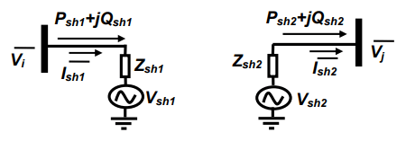
The equivalent circuit of the BtB STATCOM is shown in figure 2.
The inverter and rectifier converter are represented by voltage sources Vsh1 and Vsh2 respectively. The shunt impedance is modeled by: Zshi=rshi+jLshiω (i=1 or 2).
By performing Park transformation, the AC current transmission can be described by the following equations.
(ish = ish1 and V = Vi) for rectifier, (ish = ish2 and V = Vj ) for inverter.
BtB STATCOM regulation
Decoupled control system has been employed to achieve simultaneous control of the inverter bus voltage and the DC link capacitor voltage in the 1st region. The rectifier converter of the BtB STATCOM provides simultaneous control of real power and AC voltage (or reactive power) in the 2nd region.
The power flow control is then achieved by using properly designed controllers to force the line currents to follow their references. It is desired to obtain a fast response with minimal interaction between the real and reactive power together with a strong damping of the resonance frequency. according to equations (1) and (2), the interaction between the current loops is caused by the ωLsh coupling term. Decoupling is achieved by feeding back this term and subtracting [13, 14, 15].
The figure 3 shows the diagram of this decoupling system.

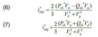
The principle of this control strategy is to convert the measured three phase currents and voltages into d-q values and then to calculate the current references and measured voltages. Taking into account equations (4) and (5), we obtain below the equations (6) and (7). The superscript defines the reference quantities. The principle of this control strategy is to convert the measured three phase currents and voltages into d-q values and then to calculate the current references and measured voltages. Taking into account equations (4) and (5), we obtain below the equations (6) and (7). The superscript defines the reference quantities.
The network equation is given by:

The figure 4 shows the model control.


The global diagram of control circuits for BtB STATCOM is given in the figure 5.

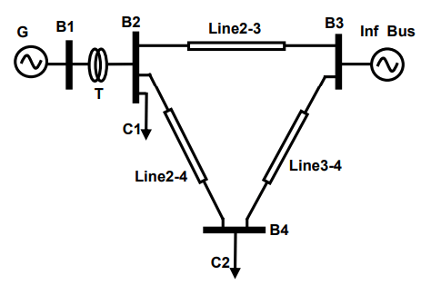
Presentation of the power system test
The power system test of the figure 6 is a Single Machine Infinite Bus (SMIB). It is made of a generator connected to an electrical network through a transformer T. The data of the system is given in the Appendix.
Insertion of STATCOM on the power system
The BtB STATCOM is installed on line 2-3 (side of bus 2) as shown in the figure 7 to force the power flow in the desired direction.

We examine the effect of BtB STATCOM on the power system in the steady state condition in order to assess its performance. The power system’s behavior is also studied when the generator is equipped of the conventional regulator. We study the influence of changing BtB STATCOM setpoints on the electrical and dynamic characteristics of the power system stability electrical in small disturbance condition.
The static behavior of the power system is examined in the absence and in the presence of BtB STATCOM. The maximum admissible power transit for each line Pmax is 300 MW. We give in all simulation scenarios:
– For load C1: Active power =1000 MW and reactive power = 0MVAR,
– For load C2: Active power = variable value and reactive power = 0MVAR.
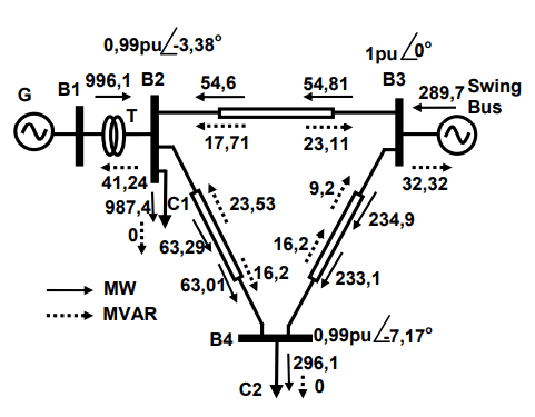
Power system simulation without BtB statcom
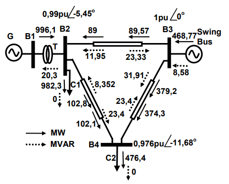
The following figure 8 shows the initial state of network voltages and load flows. For this configuration, the active power losses are equal to 2.3MW. We remark a nonuniform distribution of energy on the transmission lines: weak power flow on the lines 2-3 and 2-4, but the line 3-4 is more loaded.
The results shown in the figure 9 below are obtained for load C2=500MW. The figure 9 shows that there is an imbalance in the power flow and an increase in active power losses which reach 6.35MW. The power flow of the line 3-4 reachs 379.2MW which is greater than the maximum admissible power transit 300MW. Then the line 3- 4 is overloaded
Power system simulation with BtB STATCOM
The BtB STATCOM is installed in the power system as shown in the figures 10, 11 and 12. The voltage references and the voltage of dc link are:
V1ref = 1 pu = 230kV,
V2ref = 1pu = 230 kV,
Udc = 1 pu = 82kV.
Figure 10 shows the static behavior of the network under the following conditions: Load C2 = 300MW and PBtBSTATCOM=0MW. Note the active power transit on line 2-3 respects the order of the command P23 = P1ref = 0MW.
Consequently the load flow of line 2-4 decreases from 63,29MW to 3,122MW. Likewise, the two voltages in the two alternating sides of BtB STATCOM respect the voltage commands V1 = Vref1 = 1pu and V2 = Vref2 = 1pu. So, the STATCOM system is a capable controller to modify the transit of electrical power: Charging or discharging power lines.
Figure 11 shows the static behavior of the network under the following conditions: Load C2 = 300MW and PBtBSTATCOM=200MW. We note that the active power transmitted through line 2-3 always follows the setpoint P32=PBtBSTATCOM = 200MW, even for voltage references V1=Vref1=1pu and V2=Vref2=1pu. We also note an acceptable balance in the power flow that explains the beneficial effect of STATCOM in controlling power system. BtB STATCOM injects reactive powers into the two alternating sides to ensure the regulation of voltages V1 and V2.
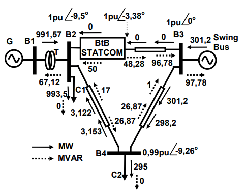
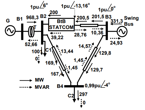
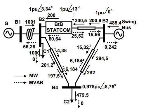
Figure 12 shows the static behavior of the network under the following conditions : Load C2 = 500MW and PBtBSTATCOM=200MW.
It can be seen that all the characteristics controlled by BtB STATCOM (V1, V2, P23) respect the command (Fig. 12). By comparing figures 12 and 9, we find the major capacity of BtB STATCOM to ensure the protection of power lines against overloads:
– Improvement of power transit in the 3 power transmission lines,
– Make the power P34 to a value (284,5MW) inferior than 300 MW (Pmax), – Voltage regulation by reactive injection to the electricity network.
Power system characteristics with BtB STATCOM
The figures 13 to 17 show the behavior of the characteristics of the generator (rotor speed, load angle, electrical power responses and voltage generator) when the system is equipped with classical regulation and BtB STATCOM.
The parameters conditions are:

In the following figures, the red curve is for the reference and the blue curve is for the response. We observe maintaining stability and synchronism of the power system after each variation of the reference Psh1ref with slight transient disturbances.


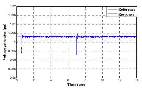
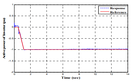
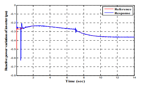
BtB STATCOM control characteristics
The figures 17, 18 and 19 show the behaviors of active power, the alternating voltage magnitude and the reactive power on the inverter side. The characteristics behaviors attest to the good performance of the used configuration of the inverter. Indeed, each response follows the order with slight disturbances at each variation of the setpoint. The progressive variation of the active power makes it possible to avoid dangerous transient peaks.

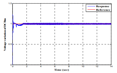
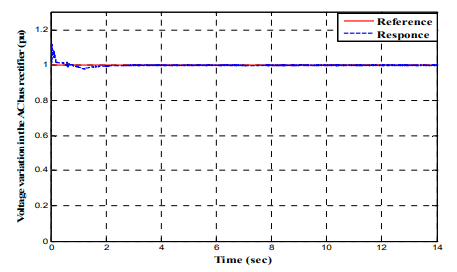
The figures 20, 21, 22 and 23 show the behaviors of the dc bus voltage, the AC voltage magnitude, the reactive power and the active power on the rectifier side. We can note also the good performance of the used configuration of the rectifier. Each characteristic response respects the order of the command with slight disturbances at each variation of the setpoint. The variation of the active power of the rectifier is confused with the active power of the inverter.


Conclusion
This paper has covered the topic of power flow models of FACTS controllers and assessed their role in wide network applications. We examined the behavior of the power system test in static state conditions when the power system operates without and with BtB STATCOM. The simulation results indicate that, by employing BtB STATCOM in the weakest bus of the system, the loading margin can be greatly increased. The results also show the effectiveness of BtB STATCOM in enhancing the load flow of the power system test. The transient mode analysis proves that the impact of setpoint variation at BtB STATCOM on the characteristics of the power system is considerably negligible. Then, a small disturbance is noted. These considerations make that a BtB STATCOM is a very powerful tool by its efficiency in the control of a power system.
APPENDIX
Table 1. System data


Table 2. Nomenclature
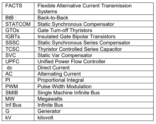
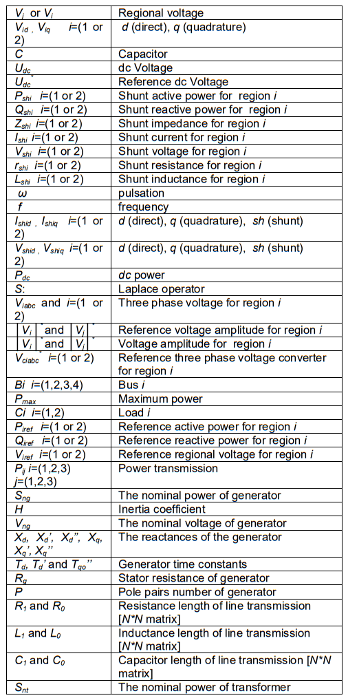
Table 3. Symbols

REFERENCES
[1] Enrique Acha, Claudio R. Fuerte-Esquivel, Hugo AmbrizPe´rez, Ce´sar Angeles-Camacho, “FACTS Modelling and Simulation in Power Networks”, BOOK Wiley Editorial Offices : Copyright # 2004 John Wiley & Sons Ltd, The Atrium, Southern Gate, Chichester, West Sussex PO19 8SQ, England.
[2] Ruslan Ufa, Alexandr Gusev, Ahmed A. Zaki Diab, Aleksey Suvorov, Nikolay Ruban, Mikhail Andreev, Alisher Askarov, Vladimir Rudnik, Omer Abdalla, Ziad M. Ali, Ahmed Ibrahim, Raef Aboelsaud, “Analysis of application of back-to-back HVDC system in Tomsk electric power system”, Energy Reports, 6 (2020), 438-444. https://doi.org/10.1016/j.egyr.2020.01.017
[3] Ahmet M. Vural, Kamil C. Bayindir., “Transient stability improvement using quasi-multi pulse BTB-STATCOM”, Advances in Energy Research, 2 (2014), No. 1, 47-59. http://www.techno- press.org/fulltext/j_eri/eri2_1/eri0201005.pdf
[4] Yeshitela Shiferaw Maru, K. Padma, “The Optimal Power Flow Solution by Optimal Location of STATCOM Device using AHP Method”, International Journal of Innovative Technology and Exploring Engineering (IJITEE), 9 (2020), Issue. 4, 2561- 2569. DOI: 10.35940/ijitee.D1944.029420
[5] Dr R. Ilango, T. Santhosh kumar, S. Sathiesh kumar, “Load Flow & Transient Stability Analysis For IEEE 5 Bus System Using UPFC”, INTERNATIONAL JOURNAL OF SCIENTIFIC & TECHNOLOGY RESEARCH Vol. 9, Issue. 4, April 2020, pp. 1349-1352. http://www.ijstr.org/final-print/apr2020/Load-Flow-TransientStability-Analysis-Forieee-5-Bus-System-Using-Upfc.pdf
[6] IMDADULLAH, SYED MUHAMMAD AMRR , M. S. JAMIL ASGHAR, IMTIAZ ASHRAF 1, MOHAMMAD MERAJ, “A Comprehensive Review of Power Flow Controllers in Interconnected Power System Networks”, IEEE Access, 8 (2020), 18036- 18063. DOI: 10.1109/ACCESS.2020.2968461
[7] Aditya Chorghade, Vandana A. Kulkarni (Deodhar), “FACTS Devices for Reactive Power Compensation and Power Flow Control – Recent Trends”, 2020 International Conference on Industry 4.0 Technology (I4Tech) Vishwakarma Institute of Technology, Pune, India. Feb 13-15, 2020, 217-221. https://ieeexplore.ieee.org/document/9102640
[8] Young Ok Lee, Hyun Jae Kang, Youngseong Han, and Chung Choo Chung, “A Nonlinear Control for a BTB STATCOM System with Asymmetrically Structured Converters”, 2011 IEEE TRONDHEIM POWERTECH CONFERENCE, JUNE 19–23, TRONDHEIM, NORWAY. https://ieeexplore.ieee.org/document/6019219
[9] Jelena Stojkovi´c , Aleksandra Leki´c, Predrag Stefanov, “Adaptive Control of HVDC Links for Frequency Stability Enhancement in Low-Inertia Systems”, Energies, 13 (2020), Issue. 23, 1-20. https://doi.org/10.3390/en13236162
[10] Alcalá, J.; Cárdenas, V.; Espinoza, J.; Durán, M., “Investigation on the limitation of the BTB-VSC converter to control the active and reactive power flow”, Electric Power Systems Research,143 (2017), 149–162. https://doi.org/10.1016/j.epsr.2016.09.012
[11] Zeng, L.; Yao,W.; Zeng, Q.; Li, D.; Fang, J.; Ai, X.;Wen, J.; He, H., “Design and real-time implementation of data-driven adaptive wide-area damping controller for back-to-back VSCHVDC”, Int. J. Electr. Power Energy Syst. 109 (2019), 558–574. https://doi.org/10.1016/j.ijepes.2019.02.024
[12] MOHAMADREZA BARADAR, “Modeling of Multi Terminal HVDC Systems in Power Flow and Optimal Power Flow Formulations”, PHD Thesis, KTH School of Electrical Engineering, SE-100 44 Stockholm, SWEDEN 2013. http://www.diva-portal.org/smash/get/diva2:588780/FULLTEXT0.pdf
[13] Yunfeng Li; Guangfu Tang; Ting An; Hui Pang; Puyu Wang; Jie Yang; Yanan Wu; Zhiyuan He, “Power compensation control for interconnection of weak power systems by VSC-HVDC”, IEEE Transactions on Power Delivery,32 (2017), No. 4, 1964–1974. DOI: 10.1109/TPWRD.2016.2602890
[14] Wang Xiang, Ruizhang Yang, Chang Lin, Jiapei Zhou, Jinyu Wen, Weixing Lin, “A Cascaded Converter Interfacing Long Distance HVDC and Back-to-Back HVDC Systems”, IEEE Journal of Emerging and Selected Topics in Power Electronics, 8 (2020), Issue. 4, 4109 – 4121. DOI: 10.1109/JESTPE.2019.2913915
[15] Yinbiao Shu, Senior, Guangfu Tang, Hui Pang, “A Back-to-back VSC-HVDC System of Yu-E Power Transmission Lines to Improve Cross-region Capacity”, CSEE JOURNAL OF POWER AND ENERGY SYSTEMS, 6 (2020), No. 1, 64-71. DOI: 10.17775/CSEEJPES.2018.01280
Authors: Kheira BELHACEL, Laboratory of Energy Engineering and Computer Engineering (L2GEGI), Department of Electrical Engineering, Faculty of Applied Sciences, University of Tiaret, BP 78 Size Zarroura, Tiaret 14000, Algeria, E-mail: belhacelelt@yahoo.fr
Dr Mohamed BOUDIAF, Laboratory of Applied Automation and Industrial Diagnostics (L2GEGI), Department of Electrical Engineering, Faculty of Sciences and Technology, University of Djelfa, BP 3117, Moudjbara Road, Djelfa 17000, Algeria, E-mail: boudhiaf_mohamed@yahoo.fr
Prof Mohamed MOUDJAHED, Laboratory of Energy Engineering and Computer Engineering (L2GEGI), Department of Electrical Engineering, Faculty of Applied Sciences, University of Tiaret, BP 78 Size Zarroura, Tiaret 14000, Algeria, E-mail: moudjahedm@yahoo.fr
Dr Abderrahmane BERKANI, Laboratory of Energy Engineering and Computer Engineering (L2GEGI), Department of Electrical Engineering, Faculty of Applied Sciences, University of Tiaret, BP 78 Size Zarroura, Tiaret 14000, Algeria, E-mail: abderrahmane.berkani@univ-tiaret.dz
Source & Publisher Item Identifier: PRZEGLĄD ELEKTROTECHNICZNY, ISSN 0033-2097, R. 98 NR 7/2022. doi:10.15199/48.2022.07.27
