Published by 1. Barbara KULESZ1, 2. Andrzej SIKORA2, 3. Damian SŁOTA3, Politechnika Śląska, Katedra Elektrotechniki i Informatyki(1,2), Politechnika Śląska, Katedra Zastosowań Matematyki i Metod Sztucznej Inteligencji (3) ORCID: 1. 0000-0002-3602-6013; 2. 0000-0003-3498-5621 3. 0000-0002-9265-5711
Abstract. The issue of the equivalent scheme parameter identification for the insulation system in an electrical machine is discussed in the paper. The presented method is based upon a recorded voltage waveform, and Artificial Bee Colony algorithm is used in calculations. A numerical example is presented.
Streszczenie. W artykule przedstawiono problem identyfikacji parametrów schematu zastępczego układu izolacyjnego maszyny elektrycznej. Zaproponowana metoda identyfikacji wykorzystuje zarejestrowane przebiegi napicia i algorytm roju pszczelego (Artificial Bee Colony Algorithm). Zamieszczono przykład obliczeniowy. (Narzędzie identyfikacji parametrów układu izolacyjnego maszyny elektrycznej).
Słowa kluczowe: maszyna elektryczna, izolacja, identyfikacja parametrów, algorytm pszczeli (ABC)
Keywords: electrical machines, insulation, parameter identification, artificial bee colony algorithm (ABC).
Introduction – insulation testing
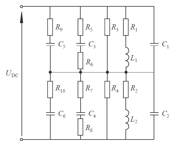
The electrical machine is a key element responsible for the correct performance of the machine. The technical condition of the insulation practically dictates the useful life of the device. Insulation is subjected to mechanical, chemical, electromagnetic, and thermal stresses; it is characterized by its resistance to heat, electrical strength, and heat conductivity coefficient. The problem of diagnosing the current state of the insulation and forecasting its progress of degradation is most important for all users of electrical machines and drives. At present, there are numerous insulation diagnostic methods exist; they can be classified e.g. on the basis of applied diagnostic voltage [2,3,4]. Among the most popular tests run with AC voltage, we may list the dielectric loss tangent tanδ measurement, partial discharge tests or the dielectric frequency response [5,7]. Among DC voltage tests, we can list the polarization method (recovery voltage test and insulation discharge current); quantities such as the polarization index (PI), capacitance of insulation system C, and the dielectric discharge DD are evaluated. Insulation may also be tested with step voltage (the voltage magnitude increases with time). When insulation-to-ground (that is, the main insulation in the machine) has been tested, turn-to-turn insulation measurements may also be performed [1,5,6]. Here, we may list the test of discharge current flowing when a loaded capacitor has been connected to the winding to the winding – surge test) or the test with voltage induced in the winding when constant current flowing through the winding has been switched off (recording of voltage waveform, assessment of induced voltage frequency and logarithmic decrement). The application of a given method depends on the goal of the measurements, available facilities/measurement devices, competence of diagnosing person/s, as well as the condition (age, wear) of insulation. Methods should be inexpensive and effective, easy to implement, and interpret. Often, more or less complex equivalent schemes are used to describe the insulation system. Such schemes take into account elements such as winding resistances and inductances, capacitances-to-ground and turn-to-turn capacitances. In practice, each different machine should be represented by its own (dedicated) equivalent scheme. An example of an equivalent scheme is shown in Fig.1. The values of the parameters in the scheme will be time-dependent (in particular, in the case of old insulation parameters, will depend on applied voltage). However, the problem is how to identify these parameters. If the present values of the parameters were determined and compared with the previous ones, it would be possible to predict the future performance of the insulation system. This would be an interesting diagnostic tool.
Description of the proposed test method
The main issue is how to reproduce the parameters of the proposed model (circuit) of the insulation system on the basis of relatively simple measurements. We propose a procedure divided into two stages. During the first stage, the insulation system should be performed using the reflected wave method. Roughly, this method consists of supplying the circuit with DC voltage in such a way that the current flowing through the winding should not exceed 10% of the winding’s rated current. The circuit is opened, and the waveform of voltage induced at the winding is recorded. An example of a recorded waveform is shown in Fig.2.
In conventional methods, the recorded waveform is used to determine voltage oscillation frequency, waveform envelope (logarithmic decrement), and maximum value of the induced voltage. In our procedure, during the second stage we shall try to mathematically reproduce the parameters of the equivalent scheme of the insulation system.

Reproduction of equivalent scheme parameters using the artificial bee colony (ABC) algorithm Problem formulation
If we want to propose a novel method for reproducing parameters of an equivalent scheme of electrical machine, the first step will be to check this method with a simple trial electric circuit. This is shown in Fig.3.

It has been assumed that this circuit should be supplied by DC current until steady-state is reached; then, switch is tripped (opened), and voltage will be induced at circuit terminals. This voltage may be expressed by the following relationship:
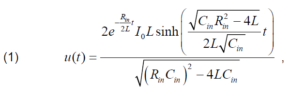
where: u(t) – voltage induced at the circuit terminals after the switch has been opened, I0 – current (DC) flowing in the circuit before opening the switch, Rin, Cin – resistance and capacitance of coil insulation, respectively, L – coil inductance.
The elements shown in Fig.3a are solely the coil parameters, i.e., wire resistance and coil inductance. The resistance and capacitance of the insulation have been taken into account in Fig3b, while the resistance has been neglected, since it is much lower than the insulation resistance. For simulation purposes, we assumed that Rin = 20 kΩ, Cin = 2 nF, L = 0.2 H, I0 = 0.5 A. An exemplary waveform has then been generated for the purpose of testing the computation method. This voltage is shown in Fig.4.
In the next step, we have formulated an algorithm for reproducing parameters of the scheme shown in Fig.3b solely on the basis of the discretized values of waveform shown in Fig.4.

Proposed computational method – swarm algorithm
The ABC algorithm was proposed by Karaboga in 2005 [8]. It has been formulated on observation of a a behaviour of swarm of bees searching for food. The exact description of the algorithm may be found elsewhere [9,10]. The algorithm may be implemented in, e.g. Mathematica software, and this procedure has been adopted here. The initial stage of the algorithm consists of setting the general algorithm parameters, setting the starting point, and first calculating the equivalent scheme parameters.
1.Parameter setting
SN (Swarm Number) – this is equal to the number of ‘bee-scouts’. We set SN at 20. D (Dimension) – this is the number of ‘food sources’ discovered (equivalent to the size of the vector xi , i = 1,…,SN). In our case, since we search for values of parameters Rin, L, and Cin, D = 3. lim – this is the number of corrective explorations around the food source xi (corrections of the ‘nectar source position’; in this case the location of the food corresponds to the values of the equivalent scheme parameters); it is assumed that lim = SNꞏD (here it is equal to 60). MCN (Maximal Cycle Number) – maximum number of cycles (iterations). We set MCN at 20.
2. Determination of the ‘starting point’
The initial population of ‘bees’ is defined; in other words, some parameters of the equivalent scheme are randomly selected. They are represented by the vector xi ,i = 1,…,SN.
3. The values of the function F(xi) are calculated, i = 1,…,SN. The function F(xi) is defined as a deviation of the waveform calculated on the basis of calculated scheme parameters (provided at the starting point) from waveform input to the procedure (Fig.4). The comparison of solutions achieved by different (subsequent) iterations is based upon comparing the obtained values of this deviation. The best possible solution – from among these calculated! – is the one where deviation is the least. Main part of the algorithm: the first ‘location of nectar sources’ (corresponding to randomly selected values of the equivalent scheme parameters) will be corrected. The values of the parameters in iteration #2 will be chosen close to the values of the parameters selected in iteration #1.
1. Modification of equivalent scheme parameters a) Formula (2) is adopted by each ‘bee-scout’ and position xi (parameter set) is thereby modified.

where
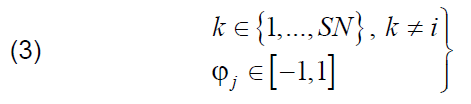
are numbers selected at random. b) Now the deviation in this step F(vi) is compared with the previous deviation F(xi) and if the following relationship
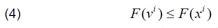
is true, then new parameters (vector vi) replace previous parameters (vector xi). If not, the parameters xi remain unchanged and the procedure shown in Step 6 is adopted. Steps (a) and (b) are repeated lim times (we try to find slight divergences of the parameters from their previous values).
2. The probabilities Pi for the positions xi selected in step 1 are calculated:
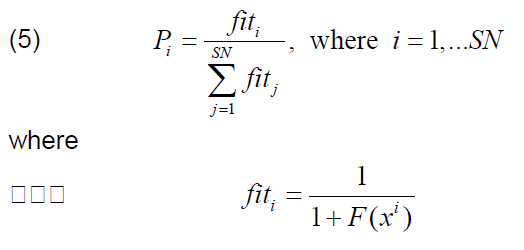
Each onlooking bee (i.e. bee-viewer) selects one ‘food source’, i.e. the parameter set xi, i = 1,…,SN (from all possible sources), with probability Pi . One set may be selected by any number of bees.
4. Next, another modification of the parameter set is performed (each onlooking bee modifies the set according to the procedure presented in Step 1).
5. The important step is to select the BEST ‘food source position’, i.e. the best parameter set xbest from among all the calculated sets. If this new xbest is better than the one selected in the earlier iteration, then it is assumed as the xbest location for the entire algorithm.
6. The alternate procedure, if the parameter set has not been improved (relationship (4) has been found to be false). The new parameter set is adopted in accordance with the following formulas:

Steps (1-6) must be repeated MCN times.
Calculation results
The selected calculation results are shown below. Since the number of full computational cycles was 20, only a few results are presented. Fig.5 presents the results in graphical form, the selected numerical results are set out in Table 1.
Table 1. Calculated equivalent scheme parameters – selected results (parameters of the reproduced waveform were Rin = 2 kΩ, L = 0.2 H, Cin = 2 nF)


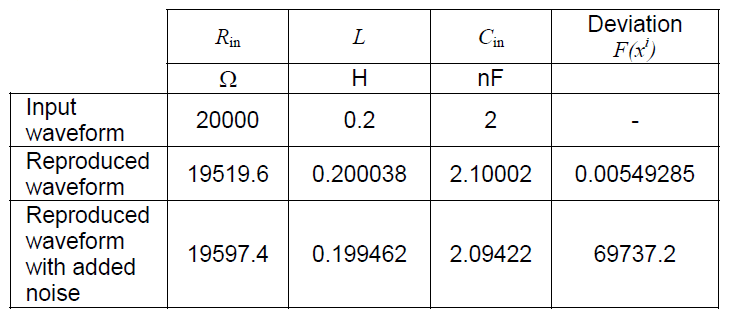
To test the influence of noise on algorithm performance, randomly-generated “disturbance” was added to the original waveform, the magnitude of the noise magnitude equal to not more than 4% of the original values. The algorithm was run, and results are shown in Fig.7.

Table 2. Comparison of calculated equivalent scheme parameters for smooth and noisy input waveform
Conclusions
We wanted to provide a tool for identification of electrical circuit parameters when a single signal waveform for this circuit is known. The proposed end purpose is to diagnose machine insulation (basing on equivalent parameters of the insulation scheme). We have applied swarm-type mathematical algorithm (ABC) to the task of identifying three parameters of electrical circuit, with induced voltage waveform acting as input data. Two cases have been analysed: with a smooth input waveform and a waveform ‘contaminated’ by random noise. The proposed algorithm performed well. Future investigations will be centred on increasing the number of circuit elements and on possible attempts to reproduce real-life signals obtained from existing insulation systems.
REFERENCES
[1] Decner A., Glinka T., Polak A., Zawilak J., Izolacja zwojowa – badania diagnostyczne, Przegląd Elektrotechniczny, nr 12/2008, 35-37
[2] Saha T.K., Review of modern diagnostic techniques for assessing insulation condition in aged transformers, IEEE Transactions on Dielectrics and Electrical Insulation,10/5 (2003), 903 – 917
[3] Saha T.K., Purkait P., Investigation of an expert system for the condition assessment of transformer insulation based on dielectric response measurements, IEEE Transactions on Power Delivery, 19/3 (2004), 1127 – 1134
[4] Stone G.C., Boulter E.A., Culbert I., Dhirani H., Electrical Insulation for Rotating Machines: Design, Evaluation, Aging, Testing, and Repair. 2nd Edition, Wiley-IEEE Press, July 2014
[5] Perisse F., Werynski P., Roger D., A New Method for AC Machine Turn Insulation Diagnostic Based on High Frequency Resonances, IEEE Transactions on Dielectrics and Electrical Insulation, 14/5 (2007), 1308 – 1315
[6] Grubic S., Aller J.M., Bin Lu, Habetler T.G., A Survey on Testing and Monitoring Methods for Stator Insulation Systems of Low-Voltage Induction Machines Focusing on Turn Insulation Problems, IEEE Transactions of Power Electronics, 55/12 (2008), 4127 – 4136
[7] Robalino D. M., Cheng J., Werelius P., Alvarez R.,A study of oil-paper insulation voltage dependency during frequency response analysis, 20th International Symposium on High Voltage Engineering, Buenos Aires, Argentina, 2017
[8] Karaboga D., Basturk B., On the performance of artificial Bee Colony (ABC) algorithm, Applied Soft Computing, 8 (2008), 687-697
[9] Hetmaniok E., Słota D., Zielonka A., Wituła R., Comparison of ABC and ACO Algorithms Applied for Solving the Inverse Heat Conduction Problem, SIDE 2012 and EC 2012, LNCS 7269, 249-257, 2012, Springer -Verlag Berlin Heidelberg.
[10] Sikora A., Kulesz B., Zielonka A., Application of swarm algorithm to solving voltage unbalance problem in DC tram traction supply system, 2018 Innovative Materials and Technologies in Electrical Engineering (i-MITEL). IEEE, 2018, DOI: 10.1109/IMITEL.2018.8370483
Autorzy: dr hab. inż. Barbara Kulesz, Politechnika Śląska, Wydział Elektryczny, ul. Bolesława Krzywoustego 2, 44-100 Gliwice, E-mail: barbara.kulesz@polsl.pl; dr inż. Andrzej Sikora, Politechnika Śląska, Wydział Elektryczny, ul. Bolesława Krzywoustego 2, 44-100 Gliwice, E-mail: andrzej.sikora@polsl.pl, prof.dr hab.inż. Damian Słota, Politechnika Śląska, Wydział Matematyki Stosowanej, ul. Kaszubska 23, 44-100 Gliwice, e-mail: Damian.slota@polsl.pl
Source & Publisher Item Identifier: PRZEGLĄD ELEKTROTECHNICZNY, ISSN 0033-2097, R. 98 NR 11/2022. doi:10.15199/48.2022.11.59
