Published by Karol ANISEROWICZ, Renata MARKOWSKA, Bialystok University of Technology
Abstract. Results of calculations of overvoltages caused by a direct lightning strike to an underground coaxial cable are presented. Analytic formulas are used in the frequency domain. The time-domain waveforms are computed using the Inverse Discrete Fourier Transform (IDFT).
Streszczenie. Przedstawiono wyniki obliczeń przepięć spowodowanych przez bezpośrednie uderzenie pioruna w podziemny kabel koncentryczny. Wykorzystano wzory analityczne sformułowane w dziedzinie częstotliwości. Przebiegi w dziedzinie czasu obliczono z zastosowaniem Odwrotnej Dyskretnej Transformacji Fouriera (IDFT). (Pół-analityczne obliczenia przepięć spowodowanych przez bezpośrednie uderzenie pioruna w podziemnym kablu współosiowym).
Keywords: lightning; overvoltages; underground cable; analytic formulation.
Słowa kluczowe: piorun; przepięcia; kabel podziemny; sformułowanie analityczne
Introduction
Lightning discharges cause substantial threat for outdoor electronic circuits and systems. This hazard concerns both overhead and underground installations, and it was analyzed in many publications [1]-[8]. In particular, electronic systems connected to long cables spread over large areas are exposed to the lightning electromagnetic pulse (LEMP).
Long underground coaxial cables are within the scope of this paper. Buried cables are commonly used, and underground sensor cables of intrusion detection systems are among them. The coaxial cable sensors together with the co-operating equipment and devices are used in monitoring systems for protection of people and property. Low energy is necessary for proper action of such system, and relatively small amount of electromagnetic energy is enough to affect the system. Sensor cables are typically buried in soil at approximately 25-40 cm below the surface and are several hundred meters long. Cable systems may be realized as standalone or networked for much longer perimeters. Their equivalent lightning discharge collection area can be of the order of square kilometers.
Problems concerning estimation of the threat related to lightning effects are usually solved numerically [5]-[7]. Analytical or semi-analytical solutions are relatively rare. The closed-form formulations are of special value because they provide examples that may be used for testing the numerical algorithms. The aim of the present paper is to calculate overvoltages that can occur in a buried sensor cable during a typical lightning strike, and to estimate the required insulation immunity to electrical breakdown. Analytic formulas are written in the frequency domain basing on [8], and the time-domain waveforms are calculated using the Inverse Discrete Fourier Transform (IDFT). A similar problem is within the scope of paper [9], where simplified calculations of surge currents and voltages in more complex buried cable systems are described. The study introduced here was used for validation of some results presented in [9].
Analytical model of buried cable
Consider a lightning strike to ground very close to one end of an underground cable (Fig. 1). A part of the lightning current invades the cable through a metal enclosure of the cable input device.
Assume that the insulation of the system withstands the threat, so the surge current flows along the cable outer conductor to the enclosure of the device on the other end of the cable. The contribution of the cable inner conductor is neglected (Fig. 1b) [8]. Dimensions a and b of the cable cross-section are the inner and outer radius of the cable insulation, respectively. The burying depth d is not used in formulas presented further.
The transmission-line model is used here [8]. The model and its equivalent circuits are presented in Fig. 2.

Current I(z) flows in the cable outer conductor, and U(z) is the voltage occurring between the cable outer conductor and the reference ground, in the insulating jacket. The soil propagation coefficient is equal to:

where µ0 and ε0 stand for the permeability and permittivity of vacuum, respectively, σg – soil conductivity, εrg – soil relative permittivity. For calculation of voltage U(z) and current I(z) (Fig. 1) it is necessary to determine characteristic impedance Z0 and propagation coefficient γ of the equivalent transmission line:
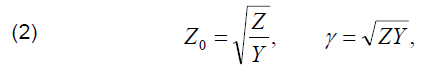
where Z and Y are the impedance and admittance per unit length, respectively.
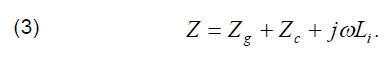
Impedance Z is composed of the internal impedance of the soil (ground) Zg, the internal impedance of the cable outer conductor Zc, and the inductive impedance of the insulating jacket jωLi [8]:
These impedances may be calculated as follows:

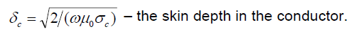
where: δg = 1/αg – the skin depth in the soil, γ0 = 1.78107… – the Euler constant, T – the thickness of the cable outer conductor, σc – the metal (copper) conductivity,
The admittance per unit length Y is composed of the capacitive admittance jωCi of the insulation in series with the unit admittance of the soil Yg [8]:

These admittances may be approximated as follows:
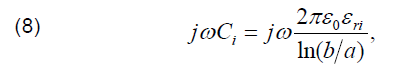

where εri is the relative permittivity of the insulating layer. The grounding resistance of the equipment connected at the cable output equals Rg2 (Fig. 1). The input impedance of the equivalent transmission line is given by:

where l is the cable length (Fig. 2a).
Current I1 being the part of the lightning current IL invades the cable outer conductor (Fig. 1). The rest of current IL is dissipated into the ground, which is modeled by current Id flowing through the grounding resistance Rg1. The following equations are valid at the cable input:

The spectra of voltage U(z, jω) and current I(z, jω) at any distance z from the cable input can be calculated using the commonly known transmission-line equations:
Calculations of overvoltages for different waveforms of lightning current
The analyzed example concerns the underground system, so one may model the lightning impact as the surge current injection. The following grounding conditions are considered: σg = 0.01 S/m, εrg = 10, Rg1 = Rg2 = 5 Ω. Assume the following parameters of the cable: 2a = 12.73 mm, 2b = 15.5 mm, l = 200 m, T = 0.33 mm, εri = 2.3, σc = 58.6×10⁶ S/m. These are typical for the intrusion detection sensors [10].
We apply the double-exponential approximation of the lightning current waveform:

Different lightning return current waveforms are used, according to [11]:
• 10/350 μs – model of the first positive stroke;
• 1/200 μs – model of the first negative stroke;
• 0.25/100 μs – model of the subsequent negative stroke.
The maximum value of the current is assumed to Im = 20 kA, which is close to typical lightning surges [12]. All the results can be easily re-calculated assuming other maximum values since the analyzed system is linear. The lightning current spectrum has the closed form:

The values of the coefficients are presented in Table 1 [5]. The right column contains also coefficients for waveform of 2/50 μs, which will be used in the next section. The time-domain waveforms are calculated numerically, using the IDFT algorithm.
Table 1. Coefficients for formulas (14)-(15) [5]

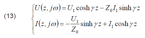
Currents IL(t), Id(t), I1(t), and I2(t) (Fig. 1a) calculated for three different surge waveforms are presented in Figs. 3-5. The associated voltages U1(t) and U2(t) are presented in Figs. 6-8, respectively.
Reflections from the cable ends are visible as smooth steps at the current and voltage waveforms.
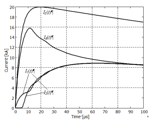

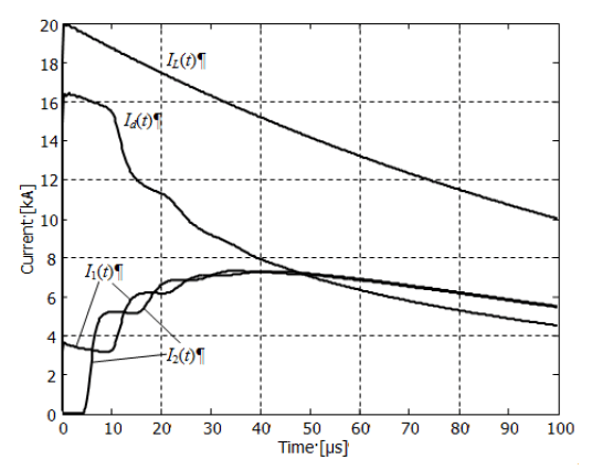
The calculated maximum values of currents in the cable outer conductor I1(t) and I2(t) are about 7.5-8.5 kA, which is about 37 % to 43 % of the maximum value of the lightning current IL(t). The highest value was obtained for the 10/350 μs waveform, and the lowest – for the 0.25/100 μs. The remaining current flows into ground.
The maximum voltages between the cable terminators and the reference ground are about 160-170 kV at the energized input and 70-90 kV at the output of the cable. Note that these voltages do not arise between the cable inner and outer conductors. They may be considered as the estimation of voltages in the cable insulation jacket, i.e. between the cable outer conductor and the ground.


Calculations of overvoltages for average lightning waveform and different grounding conditions
This section contains results that may be considered as estimation of typical lightning threat to the analyzed cable. Assume the surge current to be of 20 kA, 2/50 μs (right column of Table 1). These parameters are close to those of average lightning current [12].
Consider two different grounding conditions:
(a) σg = 0.01 S/m, εrg = 10, Rg1 = Rg2 = 5 Ω;
(b) σg = 0.001 S/m, εrg = 10, Rg1 = Rg2 = 10 Ω.

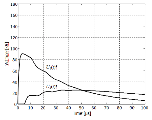

The calculated waveforms of currents and voltages are presented in Figs. 9-10 and 11-12, respectively. The results of simplified calculations for these conditions are presented in [13].
Figs. 9 and 10 show that currents depend on the grounding conditions, which is obvious, however, the current variations due to the substantial changes of the ground conductivity are not large.
In turn, Figs. 11 and 12 demonstrate that voltages for grounding conditions (b) are approximately doubled in comparison to those for case (a). The grounding resistances in case (b) are two times larger than those in case (a).
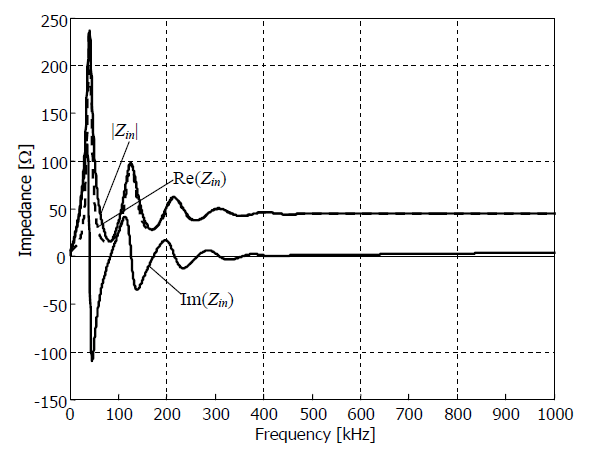
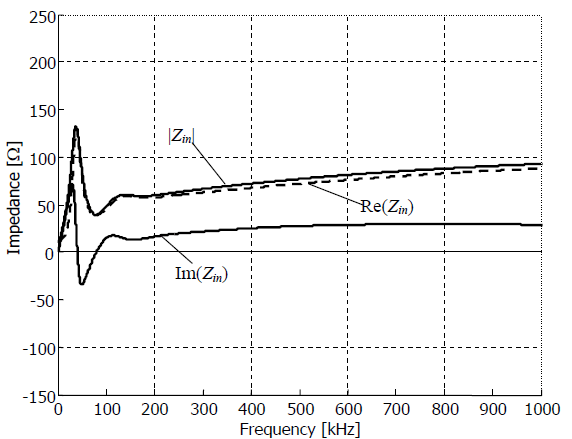
Input impedance
Frequency domain plots of input impedance Zin provide additional information for the calculation results presented in the previous section, i.e. with surge current of 20 kA, 2/50 μs and two grounding conditions
(a) σg = 0.01 S/m, εrg = 10, Rg1 = Rg2 = 5 Ω;
(b) σg = 0.001 S/m, εrg = 10, Rg1 = Rg2 = 10 Ω.
The plots of input impedances are presented in Figs. 13 and 14. At frequencies exceeding approximately 300 kHz, the modulus of the cable input impedance is approximately 1.5-2 times larger in case (b) than that in case (a). It means that the higher the ground resistivity the larger part of the high frequency components of the lightning current is dissipated by the grounding system close by the point of strike.
This observation does not concern the lowest frequency band, where the major part of the lightning energy is located. At low frequencies, the average of the modulus of the cable input impedance seems to be close to 50 Ω for both analyzed grounding conditions. This means that the low frequency components of the lightning current are distributed in the system similarly, almost irrespective to the ground resistivity.
The economically reasonable value for the grounding resistance of a buried cable sensor of the intrusion detection system is of order of 5-10 Ω in typical soil. Getting smaller values for reduction of arising potentials is usually too expensive. This means that the expected maximum voltages can be of order of tens to hundreds of kilovolts, as in Figs. 6-8 and 11-12.
Insulation coats of many cables probably cannot withstand such a stress. Additionally, the current flow of order of kiloamperes over a time exceeding 100 μs leads to significant increase in the cable temperature causing its damage. Hence, additional surge protective devices (SPDs) are necessary for protection against lightning [11].
Conclusion
Analytic formulation presented here may be useful for testing new numerical procedures.
The calculated voltages and currents are related to approximately average lightning current of 20 kA. In the IEC standard [11] the maximum current value is said to be of 200 kA. This means that the values displayed here can be of order larger. Cable conductors and insulation coats of many cables cannot withstand such a stress without additional protection measures.
It follows from the calculations that striving for the possibly lowest grounding resistance is of essential importance for reduction of the lightning hazard in buried cables. Note that the soil conductivity is not a critical parameter, although technical means of achieving required grounding resistance depend on the soil conductivity.
Grounding is not a sufficient measure of protection against lightning damages in buried cables. Additional surge protective devices should be installed at both cable ends.
Acknowledgment: The research was conducted within the project S/WE/1/2015, financially supported by Polish Ministry of Science and Higher Education.
REFERENCES
[1] Tominaga T., Kuwabara N., Kato J . , Ramli A., Hal im A. , Ahmad H. , Characteristics of Lightning Surges Induced in Telecommunication Center in Tropical Area, IEEE Transactions on Electromagnetic Compatibility, vol. 45, no. 1, 2003, p. 82–91
[2] Bejleri M., Rakov V. A., Uman M. A., Rambo K. J . , Mata C. T., Fernandez M. I., Triggered lightning testing of an airport runway lighting system, IEEE Transactions on Electromagnetic Compatibility, vol. 46, no. 1, 2004, p. 96–101
[3] Barbosa C. F., Zeddam A., Day P., Bourgeois Y. , Effect of guard wire in protection a telecommunication buried cables struck by rocket-triggered lightning, Proc. of 29th International Conference on Lightning Protection, 23-26 June 2008, Uppsala, Sweden, p. 6b-1-1–6b-1-6
[4] Kuramoto S., Chikai S. , Suzuki T., Tada Y. , Evaluation of lightning surge current characteristics induced on the aerial subscriber’s cable at telecommunication center and in NTT, Proc. of 28th International Conference on Lightning Protection, 2006, Kanazawa, Japan, p. 529–532
[5] Aniserowic z K., Analysis of electromagnetic compatibility problems in extensive objects under lightning threat monograph, in Polish, Bialystok 2005, pdf available at http://pbc.biaman.pl/dlibra
[6] Markowska R., Sowa A., W., Ochrona odgromowa obiektów radiokomunikacyjnych, Oficyna Wydawnicza Politechniki Białostockiej, Białystok 2013
[7] Masłows ki G., Analiza i modelowanie wyładowań atmosferycznych na potrzeby ochrony przed przepięciami, Wydawnictwo AGH, Kraków 2010
[8] Vance E. F., Coupling to shielded cables, Wiley – Interscience, 1978
[9] Mar kowska R. , Ani serowi c z K. , Exposure of underground cable intrusion detection system to overvoltages caused by lightning strike, Proc. of 24th International Conference on Electromagnetic Disturbances EMD’2017, 20-22 September 2017, Bialystok, Poland, 73-76
[10] Technical data sheet – Radiating cables, Kabelwerk, EUPEN AG, Rev.: 08/2010-10-07
[11] IEC 62305, Protection against lightning, series of standards, 2010
[12] Uman M. A., Natural lightning, IEEE Transactions on Industry Applications, 30 (1994), No. 3, 785-790
[13] Aniserowic z K., Markows ka R. , Semi-analytic calculations of overvoltages caused by direct lightning strike in buried coaxial cable, Proc. of 24th International Conference on Electromagnetic Disturbances EMD’2017, 20-22 September 2017, Bialystok, Poland, 9-12.
Authors: dr hab. inż. Karol Aniserowicz, prof. nzw. w PB, Politechnika Białostocka, Wydział Elektryczny, ul. Wiejska 45d, 15- 351 Białystok, e-mail: k.aniserowicz@pb.edu.pl; dr hab. inż. Renata Markowska, Politechnika Białostocka, Wydział Elektryczny, ul. Wiejska 45d, 15-351 Białystok, e-mail: r.markowska@pb.edu.pl.
Source & Publisher Item Identifier: PRZEGLĄD ELEKTROTECHNICZNY, ISSN 0033-2097, R. 93 NR 12/2017. doi:10.15199/48.2017.12.01
