Published by Karol ANISEROWICZ, Politechnika Białostocka, Wydział Elektryczny
ORCID: 0000-0001-8895-3954
Abstract. The paper presents a comparison of results of determining the lightning current flow in the shield wires of a high voltage line, using the model of lightning in the form of a lumped current generator and the antenna model, which takes the electromagnetic coupling into account. The usability of these two models is discussed.
Streszczenie. Przedstawiono porównanie wyników wyznaczenia rozpływu prądu piorunowego w linkach odgromowych linii wysokiego napięcia, z użyciem modelu pioruna w postaci skupionego generatora prądowego oraz modelu antenowego, uwzględniającego sprzężenie elektromagnetyczne. Przedyskutowano użyteczność tych dwóch modeli. (Porównanie dwóch koncepcji modelowania uderzenia pioruna w linię napowietrzną).
Słowa kluczowe: piorun, prąd, przebieg, widmo.
Keywords: lightning, current, waveform, spectrum.
Introduction
Numerical or experimental simulations of currents caused by direct lightning strikes into various structures need significant effort during modeling so as to get an acceptable approximation to the real phenomenon. One of the problems to be solved is the model of the lightning itself [1]. A model of a long lightning channel (up to several kilometers) should be applied. However, this causes substantial increase of computer effort necessary for numerical simulations. Considerable difficulties are met also when constructing a sufficiently tall experimental stand. In practice, only very costly rocket-triggered lightning experiments give credible results [2].
Lumped surge generators are used in many studies for modeling the lightning current. Disregarding the impact of the electromagnetic field accompanying the long lightning channel can lead to errors that may be unacceptably large [3]-[5]. Nevertheless, lumped generators are in use for estimation of lightning threat in specific cases, e.g., [6]-[7].
Despite the criticism found in the literature [3]-[5], a question may be asked whether using lumped generators for calculations or experiments can lead to tolerable approximations to reality in some selected cases.
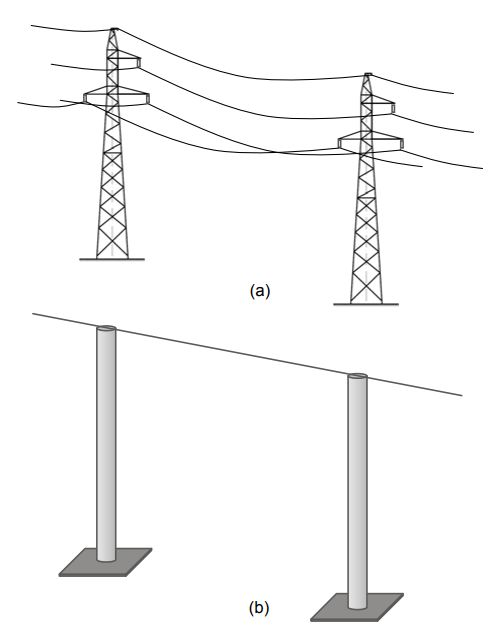
In this paper, an answer to this question is given, using a simplified model of an overhead transmission line (Fig. 1). A comparison of calculations of lightning currents in the transmission line is done using two different models of lightning. The first model simulates an experimental setup with a lumped current generator (Fig. 2a). The second one takes into account the length of the lightning channel (Fig. 2b), thus reproducing the electromagnetic coupling to the analyzed structure.
Numerical Model
The assumed overhead line dimensions are close to those applied in Poland for 110 kV lines. Only towers and shield wires (lightning protection wires) are taken into account. The AC wires are not modeled (Fig. 1b). The ground and all the wires are assumed to be perfectly conducting. The model of the line and two analyzed models of lightning are presented in Figure 2. Assume that lightning strikes the line in the middle. Only fragments of the models, close to the point hit by lightning are shown.
Calculations were performed in the frequency domain using the Method of Moments (AWAS-2 computer code [8]). The AWAS-2 code uses the polynomial approximation of current distribution along the segments, up to the order of 9.
The transformation to the time domain was done using the Discrete Fourier Transform [4]. 2048 spectrum samples were taken into account, with interval Δf = 1 kHz.
The models with the lumped current generator (Fig. 2a) and with the lightning antenna-theory model [4], [9] (Fig. 2b) consist of 362 and 511 segments, respectively.
The dimensions of the line model are as follows:
‐ towers – height of 25 m, radius of 1 m;
‐ line section length (distance between towers) – 250 m;
‐ length of segments of shielding wires – 50 m; wire radius – 5.5 mm (cross section of 95 mm2);
‐ line total length – 15 km (60 sections);
‐ lightning channel model – a vertical antenna of height of 7525 m, radius 5 cm, divided into segments of length of 50 m, the RL load uniformly distributed along the channel, Rd = 1 Ω/m, Ld = 4.5 µH/m [4].
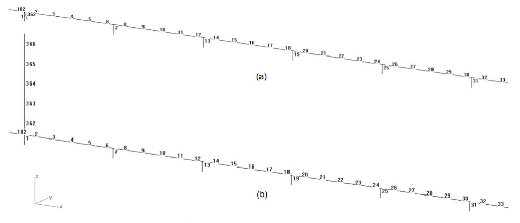
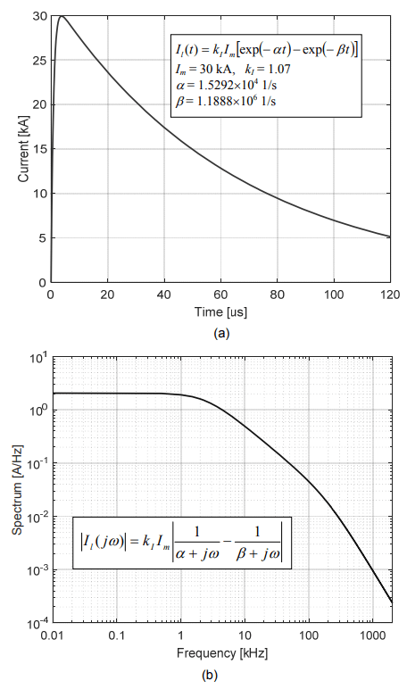
The double-exponential lightning current waveform of 30 kA, 2/50 µs is assumed (Fig. 3). These values are within the typical ranges of the current parameters of the lightning first negative downward strokes [10]-[11]. The source of the lightning current is located in segment no. 362 (Fig. 1).
Results in the time domain
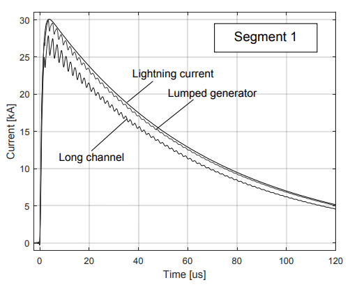
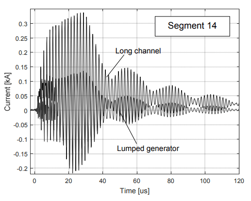
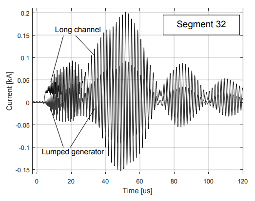
The current waveforms caused by the lumped current generator and by the long lightning channel, calculated in segments no. 1, 2, 14 and 32, are compared in Figs. 4, 6, 8 and 10, respectively. The corresponding waveforms can be considered approximately similar to one another only in Fig. 4, which presents the current in the tower being struck by lightning. The differences between waveforms presented in Figs. 6, 8 and 10 are unacceptably large.
The resonances of the structure are predicted by both analyzed models. The damped oscillations visible in the plots are related to the loop formed by the shielding wire (of length of 250 m), two neighboring towers (of height of 25 m) and their underground image. Hence, the corresponding wave length can be approximated as
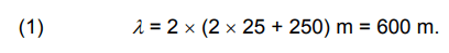
The frequency of the first resonance can be estimated as f = c/λ = 500 kHz (see also Figs. 5, 7, 9 and 11). The period of the oscillations T = 1/f = 2 µs. The envelopes of the decreasing oscillations presented in Fig. 8 at t > 45 µs and in Fig. 10 at t > 70 µs have their period of 25 µs.
These envelopes are visible in current waveforms caused both by the lumped generator and by the model of the long lightning channel. This period is related to a wavelength of 7.5 km, which equals the distance from the central point being struck by lightning to the line end.
Results in the frequency domain
The reason for the noticeable waveform differences can be deduced from Figs. 5, 7, 9 and 11, where the frequency domain characteristics are shown. The presented moduli of the current transmittances are defined as
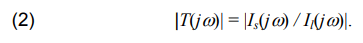
where Is is the current in segment s, and Il – the lightning current (in segment no. 362 – Fig. 2).
The transmittances may be considered comparable only in segment no. 1 (Fig. 5). The relative difference between the plots is about 10% in Fig. 5. The higher the segment number the larger the differences between the transmittance moduli at low frequencies. Those differences can be of several orders of magnitude (Figs. 9 and 11). Note that the major part of the lightning energy is also concentrated in that frequency band (Fig. 3b).

Conclusion
Due to the relatively large line section length, the analysis of the lightning threat of the tower directly hit by lightning (segment no. 1) may be considered acceptable without taking the radiation of the lightning channel into account. The use of the lumped current generator leads to an acceptable overestimation there (~10%). This is because the major part of the lightning current flows down the tower being hit.
Main resonant frequencies are correctly predicted by both models.
However, if one wants to analyze currents in the shield wires and in the subsequent towers, then the electromagnetic coupling between the long lightning channel and the analyzed structure cannot be neglected because of inconsistency of the results produced by the use of the lumped current generator.
This work was realized in the Bialystok University of Technology, Poland, and supported by the Polish Ministry of Education and Science under Rector’s Project WZ/WEIA/1/2020.
REFERENCES
[1] Cooray V., An introduction to lightning, Springer, (2015)
[2] Rakov V.A., A review of triggered lightning experiments, in Proc. 30 Int. Conf. Lightning Protection, Invited Lecture L3, Cagliari (2010)
[3] Cristina S., Orlandi A., Lightning channel’s influence on currents and electromagnetic fields in a building struck by lightning, in Proc. IEEE Int. Symp. Electromagn. Compat., (1990), 338-342
[4] Aniserowicz K., Analysis of electromagnetic compatibility problems in extensive objects under lightning threat (monograph, in Polish, http://pbc.biaman.pl/dlibra), Białystok, (2005)
[5] Aniserowicz K., Analysis of features of selected models for simulation of lightning threat, in Proc. Int. Symp. and Exhibit. Electromagn. Compat. EMC Europe (2016), Wrocław, 339-342.
[6] Metwally I.A., Heidler F.H., Zischank W.J., Magnetic fields and loop voltages inside reduced and full-scale structures produced by direct lightning strikes, IEEE Trans. Electromagn. Compat., 48 (2), (2006), 414-426.
[7] Masłowski G., Rakov V.A., Wyderka S., Ziemba R., Karnas G., Filik K., Current impulses in the lightning protection system of a test house in Poland, IEEE Trans. Electromagn. Compat., 57 (3), (2015), 425-433.
[8] Djordjevic A.R., Bazdar M.B., Petrovic V.V., Olcan D.I., Sarkar T.K., Harrington R.F., AWAS 2.0 for Windows: Analysis of Wire Antennas and Scatterers, Artech House, (2002)
[9] Rakov V.A., Uman M.A., Review and evaluation of lightning return stroke models including some aspects of their application, IEEE Trans. Electromagn. Compat., 40 (4), (1998), 403-426
[10] Uman M.A., Natural lightning, IEEE Trans. Industry Apps, 30 (3), (1994), 785-790
[11] Working Group C4.407, Lightning parameters for engineering applications, CIGRE report 549, (2013)
Author: dr hab. inż. Karol Aniserowicz, prof. uczelni, Politechnika Białostocka, Wydział Elektryczny, ul. Wiejska 45D, 15-351 Białystok, E-mail: k.aniserowicz@pb.edu.pl.
Source & Publisher Item Identifier: PRZEGLĄD ELEKTROTECHNICZNY, ISSN 0033-2097, R. 97 NR 12/2021. doi:10.15199/48.2021.12.17
