Published by 1. Stanislaw CZAPP, 2. Daniel KOWALAK, Gdańsk University of Technology
ORCID: 1. 0000-0002-1341-8276; 2. 0000-0001-9610-9884
Abstract. The scope of the verification of low-voltage systems covers the earth fault loop impedance measurement. This measurement is usually performed with the use of low-value current meters, which force a current many times lower than the one occurring during a real short-circuit. Therefore, the international standard recommends consideration of the increase of resistance of conductors with the increase of temperature, which may occur during short-circuits. This paper analyses the temperature rise of the conductors during short-circuits, taking into account the let-through energy of protection devices. The analysis has shown that in typical circuits the temperature rise of conductors is not significant.
Streszczenie. W ramach kontroli stanu instalacji niskiego napięcia wykonuje się pomiar impedancji pętli zwarciowej wymuszając prąd znacznie mniejszy niż występujący podczas rzeczywistego zwarcia. Norma dotycząca sprawdzania instalacji niskiego napięcia zaleca, aby w przypadku pomiarów małym prądem, w temperaturze pokojowej, uwzględnić fakt, że podczas zwarcia temperatura i rezystancja przewodów może wzrosnąć, co zaostrza warunek skuteczności ochrony przeciwporażeniowej. W artykule przeanalizowano, w jakim stopniu może wzrosnąć temperatura przewodów podczas zwarć przy uwzględnieniu całki Joule’a wyłączania zabezpieczeń nadprądowych. Z analizy wynika, że wzrost ten jest niewielki. (Wpływ energii przenoszonej przez zabezpieczenia nadprądowe na wzrost temperatury przewodów podczas zwarć).
Keywords: conductors resistance, let-through energy, overcurrent protection, short-circuit.
Słowa kluczowe: rezystancja przewodów, energia przenoszona, zabezpieczenie nadprądowe, zwarcie.
Introduction
Earth faults both in high- and low-voltage systems may introduce an electric shock hazard. Every safety system, including a system of protection against electric shock, should fulfil at least the (n – 1) condition, i.e. the protection is ensured in case of the first fault (usually an insulation fault). In low-voltage systems, the most popular method of protection in case of a fault (protection against indirect contact) is the automatic disconnection of supply. The line-to-earth short-circuit current should be high enough to initiate tripping of the disconnecting device (circuit-breaker, fuse or residual current device) within the time specified in standard PN-HD 60364-4-41 [1]. This short-circuit current value depends on the value of the loop impedance of the faulty circuit. In order to achieve the effectiveness of protection against electric shock by automatic disconnection of supply, the following condition has to be fulfilled:
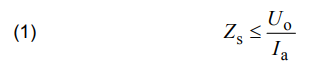
where: Zs – is the earth fault loop impedance (TN-type systems) determining the value of the line-to-earth (earth fault) current; Uo – is the nominal line-to-earth voltage; Ia – is the current causing the automatic operation of the disconnecting device within the specified time [1].
The effectiveness of protection against electric shock is required to be confirmed during the initial and periodic verification of low-voltage electrical installations [2-7]. The scope of this verification is included in standard PN-HD 60364-6 [8]. According to this standard, in TN-type systems (the most common), where possible, the measurement of the earth fault loop impedance is recommended to be carried out.
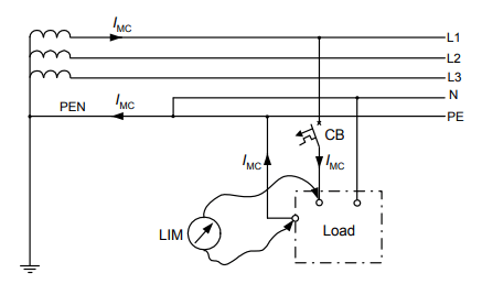
In practice, the loop impedance is measured with the use of the artificial short-circuit method. This method is utilized by the meters widely accessible in the market. During the measurement, the testing current IMC is forced (Fig. 1), and its value is from milliamps up to several hundred amps – it depends on the type of the meter.
Standard PN-HD 60364-6 [8] informs that consideration of the increase of the resistance of the conductors with the increase of temperature is recommended. For a relatively high value of the temperature of the conductors (in effect it gives a relatively high resistance), the earth fault current can be too low to initiate tripping of the protection device. It is written in this standard (Annex D – informative) that in the case of the measurement at room temperature, with the use of low-current methods (a practically negligible increase of the temperature of the conductors), the measured earth fault loop impedance in TN systems should satisfy the following dependence:

where: Zsm – is the measured earth fault loop impedance.
Such a dependence makes that conditions for effective protection against electric shock are clearly more rigorous (coefficient 2/3). Thus, according to the standard [8], when the measured impedance Zms exceeds the value described by (2), the more detailed calculation should be performed. In particular, the let-through energy of the protective device installed in the tested circuit should be taken into account.
This paper covers the effect of the let-through energy of the protective device on the real increase of the conductors/cables temperature in case of short-circuits (earth faults). Results of the laboratory test of the let-through energy of selected miniature circuit-breakers and fuses are presented. On the base of this laboratory test and data delivered by the manufacturers of the overcurrent protection devices, the temperatures of conductors, in case of an earth fault, are calculated for an example electrical installation.
Resistance of conductors vs. their temperature
Resistance of conductors Rc and in consequence the loop impedance Zs (Zsm) given by (1) and (2), strictly depends on the conductors’ temperature. The resistance can be calculated according to:

where: l – is the length of the conductor; γx – is the conductivity of the conductor in temperature x; s – is the cross-sectional area of the conductor.
The conductivity γx in the temperature x is calculated in the following way:
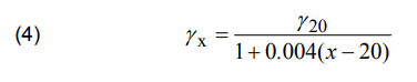
where: γ20 – reference conductivity of the conductor (in 20 °C); x – given temperature of the conductor.
For commonly used PVC-insulated cables/conductors, the permissible continuous temperature is equal to 70 °C. In this temperature, the resistance of conductors is higher by 20% than in 20 °C:

From the point of view of the effectiveness of the automatic disconnection of supply, it is important to evaluate the real temperature rise of the conductors during a short-circuit. The temperature rise v can be evaluated according to the following dependence [9]:
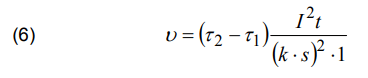
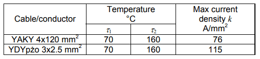
where: 𝜏1 – is the temperature of the conductor before a short-circuit; 𝜏2 – is the max permissible temperature of the conductor in the case of a short-circuit; I2t – is the let-through energy of the protective device; k – is the max permissible current density in the conductor (within 1 second); s – is the cross-sectional area of the conductor.
For a given type of a cable/conductor, the temperatures 𝜏1 and 𝜏2 as well as parameters k and s are known. The Joule integral (let-through energy) I2t of the protection device can be derived from manufacturers data, but the authors performed also a laboratory test to find out the real values of this parameter.
Results of the laboratory test and calculations
Figure 2 presents the structure of the analyzed example installation. It is assumed that the single-phase loads are supplied via PVC-insulated power cable having aluminium conductors (120 mm2) and PVC-insulated copper conductors (2.5 mm2). The first final circuit is protected by a miniature circuit-breaker (MCB) and the second by a fuse.
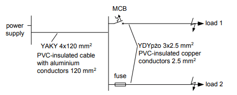
Based on the diagram from Fig. 2, the characteristic parameters of the power cable and final circuits’ conductors are as in Table 1.
Table 1. Parameters of the analyzed cable/conductors
In the investigation of the circuit marked “load 1”, the following types of the MCBs have been taken into account: B16, C16 and D20. The MCBs B16 and C16 are the most common types installed in final circuits. Also, the conductor of the cross-sectional area 2.5 mm2 (Fig. 2) is very popular in low-voltage final circuits.
First, as an example, the temperature rise of the conductor during a short-circuit has been evaluated on the base of the manufacturers’ data for the MCB of B16 type. Such data are presented in Fig. 3.
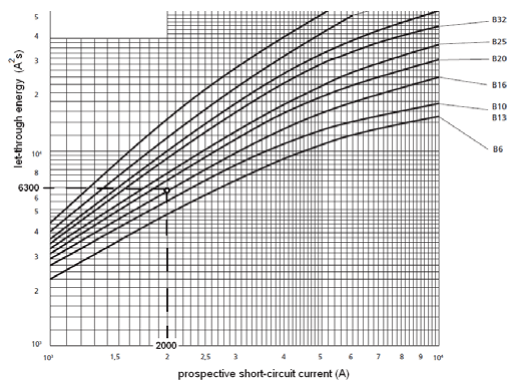
For a prospective short-circuit current equal to 2 kA, the value of the B16 MCB let-through energy is equal to 6300 A2s (Fig. 3). According to (6) and Tab. 1, it gives the temperature rise of the conductor YDYpżo 3×2.5:
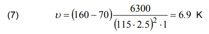
For the cable YAKY 4×120, the temperature rise is as follows:
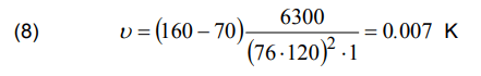
One can see that the temperature of the conductor YDYpżo 3×2.5 increases only slightly. In case of the cable YAKY 4×120, the increase is completely negligible.
In order to check the real temperature rise, the laboratory test of the MCBs let-through energy has been carried out. Figures 4, 5, and 6 present results of this test for the MCBs B16, C16 and D20 respectively. The process of current breaking and the let-through energy value have been verified for prospective short-circuit currents 1 kA and 2 kA. Results of the temperature rise calculation, for data obtained from the laboratory test, are presented in Table 2.

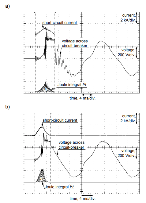

Table 2. Temperature rise of the cable/conductors in circuits protected by MCBs
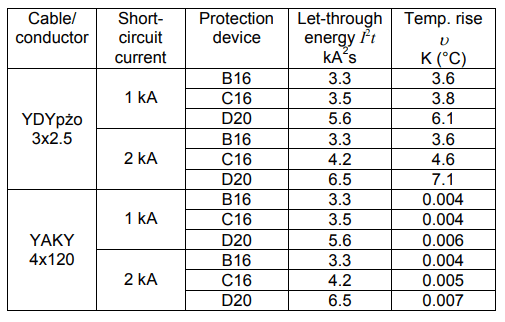
If one compares the value of the maximum let-through energy for the MCB B16 derived by the manufacturer (Fig. 3: I2t = 6300 A2s, for 2 kA) with the let-through energy obtained during the laboratory test (Fig. 4b: I2t = 3300 A2s, for 2 kA), it is seen that the latter is almost two times lower. It gives only the 3.6 K temperature rise of the conductor YDYpżo 3×2.5 in case of a short-circuit with current 2 kA. The temperature rise of the cable YAKY 4×120 is – obviously – negligible (0.004 K). For other MCBs (C16 and D20) the temperature rise of the conductor YDYpżo 3×2.5 is maximum around 7 K and for the cable YAKY 4×120 is close to 0 K.
Even a lower temperature rise is expected in the circuit marked “load 2” (Fig. 2) protected by a fuse. In the investigation, the following general type fuses are taken into account: gG16 and gG20. If the normative maximum values of the let-through energy I2t are considered (Tab. 3), the temperature rise of the conductor YDYpżo 3×2.5 protected by a fuse gG16 (I2t = 1210 A2 s) is equal to 1.32 K (Tab. 4). This temperature rise is valid for both analyzed values of the prospective short-circuit currents 1 kA and 2 kA because the let-through energy is approx. constant (from 550 A onwards for gG16 – see Tab. 3). In the case of the cable YAKY 4×120, the temperature practically does not change the value (0.0013 K).
Table 3. Maximum let-through energy I2t of the gG fuses (IEC) [11]
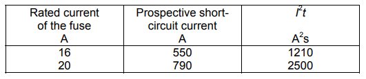
Table 4. Temperature rise of the cable/conductors in circuits protected by gG fuses

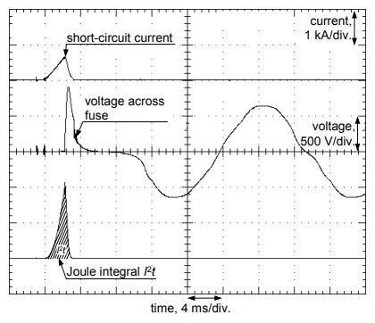
Calculation of the temperature rise on the base of the selected manufacturer data (“ETI”, Tab. 4) enables to say that gG16 fuses have let-through energy not higher than 1060 A2 s, what is clearly lower than the max normative value (1210 A2 s – see. Tab. 3). This value also gives a very small increase in the temperature of the conductor YDYpżo 3×2.5 (1.15 K). A laboratory test of the fuses shows (“Lab”, Tab. 4) that in practice the let-through energy can be significantly lower than the manufacturer declaration (positive effect). Example oscillograms obtained from the testing of a fuse are presented in Fig. 7.
From the above-conducted calculations performed for the example electrical installation, with components having typical parameters, it can be determined that in the case of short-circuits, the temperature rise of the final conductor is relatively low and the temperature rise of the cable in a distribution circuit is practically negligible. This is due to the positive effect of the protection devices in terms of letthrough energy. Thus, during the earth fault loop impedance measurement, the safety margin presented by the expression (2) is too restrictive. Instead of the 2/3 value, this margin is acceptable to be expressed by the value around 0.90÷0.95.
Conclusions
Analysis of the values of the let-through energy of the protection devices, which are installed in typical low-voltage final circuits shows that the coefficient 2/3 included in the expression (2) gives too restrictive conditions in terms of the effectiveness of automatic disconnection of supply. Fortunately, this expression is only informative (not obligatory), and it is easy to prove that in the case of a short-circuit the temperature rise and resistance rise of the conductors are practically insignificant.
REFERENCES
[1] PN-HD 60364-4-41:2017-09 Low-voltage electrical installations – Part 4-41: Protection for safety – Protection against electric shock
[2] Neitzel D.K., Electrical Safety Update – OSHA 29 CFR 1910.269 and NFPA 70E®-2015 Revisions, IEEE Industry Applications Society Annual Meeting, Addison, TX, USA, (2015), 1-6
[3] Roskosz R., Musiał E., Czapp S., A method of earth fault loop impedance measurement without unwanted tripping of RCDs, Progress in Applied Electrical Engineering (PAEE), Kościelisko, Poland, (2018) 1-4
[4] Czapp S., Method of earth fault loop impedance measurement without nuisance tripping of RCDs in 3-phase low-voltage circuits, Metrol. Meas. Syst., 26 (2019), No. 2, 217-227
[5] Czapp S., Fault loop impedance measurement in low voltage network with residual current devices, Elektronika ir Elektrotechnika, 122 (2012), No. 6, 109-112
[6] Aigner M., Schmautzer E., Sigl Ch., Wieland T., Fickert L., Fehlerschleifenimpedanz-Messung in Niederspannungsnetzen mit Wechselrichtern. 8. Intern. Energiewirtschaftstagung an der TU Wien, IEWT, (2013)
[7] Roskosz R., Ziolko M., Measurement accuracy of shortcircuit loop impedance in power systems, Proc. XVII IMEKO World Congress, TC4, Dubrovnik, Croatia, (2003), 903-907
[8] PN-HD 60364-6:2016-07 Low-voltage electrical installations – Part 6: Verification
[9] Musiał E., Obciążalność cieplna oraz zabezpieczenia nadprądowe przewodów i kabli, Informacje o Normach i Przepisach Elektrycznych, 107 (2008), 3-41
[10] Miniature circuit-breakers. Technical data, ETI, 2017
[11] IEC 60269-2:2013 Low-voltage fuses – Part 2: Supplementary requirements for fuses for use by authorized persons (fuses mainly for industrial application) – Examples of standardized systems of fuses A to K
[12] Fuse-links and equipment. Technical data, ETI, 2019
Authors: dr hab. inż. Stanisław Czapp, prof. PG, Politechnika Gdańska, ul. G. Narutowicza 11/12, 80-233 Gdańsk, Poland, E-mail: stanislaw.czapp@pg.edu.pl dr inż. Daniel Kowalak, Politechnika Gdańska, ul. G. Narutowicza 11/12, 80-233 Gdańsk, Poland, E-mail: daniel.kowalak@pg.edu.pl
Source & Publisher Item Identifier: PRZEGLĄD ELEKTROTECHNICZNY, ISSN 0033-2097, R. 97 NR 8/2021. doi:10.15199/48.2021.08.05
