Published by Abdelkrim ZEBAR, Department of Electrical Engineering, Faculty of technology, Ferhat Abbas Setif 1 University, Setif, Algeria
Abstract. The increase of environmental pollution and the decreasing of the energy is extremely related to social progress. The resolution of the environment pollution depends on renewable energy such as wind energy system. Though, that system is required by transient and voltage stability issues with wind energy employing fixed-speed induction generators to be augmented with resistive type superconducting fault current limiter (SFCL) and dynamic compensation devices, such as a Static Synchronous Compensator units (STATCOM). The use of combined model based SFCL and STATCOM for promoting the transient and voltage stability of a multi-machine power system considering the fixed-speed induction generators is the primarily focus of this study. The proposed combined model functions top reserve simultaneously a flexible control of reactive power using STATCOM controller and to reduce fault current using superconducting technology based SFCL. The effectiveness of the proposed combined model is tested on the IEEE11-bus test system applied to the case of three-phase short circuit fault in one transmission line. A simulation results are presented in this document.
Streszczenie. Proponowany w artykule połączony model ma najwyższą rezerwę jednocześnie elastyczną kontrolę mocy biernej za pomocą kontrolera STATCOM i redukcję prądu zwarciowego za pomocą SFCL opartej na technologii nadprzewodnictwa. Skuteczność proponowanego modelu łączonego jest testowana na systemie testowym magistrali IEEE11 stosowanym w przypadku zwarcia trójfazowego zwarcia w jednej linii przesyłowej. Wyniki symulacji przedstawiono w tym artykule. (Statyczny synchroniczny kompensator i nadprzewodzący ogranicznik prądu dla systemu przesyłowego z generatorem wiatrowym)
Keywords: Distributed wind generation (DWG) , superconducting fault current limiter (SFCL), Static Synchronous Compensator (STATCOM), Transient stability.
Słowa kluczowe: Rozproszone system z z generatoirem wiatrowym (DWG), Nadprzewodnikowy ogranicznik prądu zwarciowego (SFCL), Statyczny synchroniczny kompensator (STATCOM), Stabilność przejściowa.
Introduction
Recently, the wind power generation included in the standard grid showed a further increase, in a significant way so, the electric utilities grid codes are forced to be revised, thus the reliability in systems with high wind energy diffusion will be guaranteed [1]. In power system stability studies the term transient stability usually refers to the ability of the synchronous machines to remain in synchronism during the brief period following large disturbances, such as severe lightning strikes, loss of heavily loaded transmission lines, loss of generation stations, or short circuits on buses [2]. To cope with the increasing demand for electric power, more and more FACTS devices are employed to improve the transmission capability of existing transmission facilities. As a result, the stability margin of power systems has decreased while the complexity of power systems has increased considerably. Thus, new techniques in power system control which can improve the dynamic performance and transient stability of power systems present an even more formidable challenge[3].
The STATCOM is one of the important FACTS devices and can be used for dynamic reactive power compensation of power systems to provide voltage support and stability improvement [4-5].
The use of Fault Current Limiters (SFCLs) is being evaluated as one element necessary to limit the fault current and enhance the power system transient stability [6]. A superconducting fault current limiter (SFCL) is a device with negligible impedance in normal operating conditions that reliably switches to a high impedance state in case of extra-current. Such a device is able to increase the short circuit power of an electric network and to contemporarily eliminate the hazard during the fault. It can be regarded as a key component for future electric power systems [7-8].
One of the requirements of transient stability analysis is to compute a transient stability index (TSI) for the contingencies, which is used to assess the stability of single contingency and furthermore rank the severity of different contingencies [9]. The Critical Clearance Time (CCT) of a fault is generally considered as the best measurement of severity of a contingency and thus widely used for ranking contingencies in accordance with their severity [10]. In this paper Critical Clearing Time (CCT) is employed as a transient stability index to evaluate test system. The Critical Clearing Time is defined as “the maximum time between the fault initiation and its clearing such that the power system is transiently stable”.
Many methods for transient stability analysis and assessment have been proposed and improved over the years, such as equal area criteria, numerical integration and Lyapunove method, in this study the numerical integration method is required in order to get the exact CCTs. The numerical integration method is the most reliable and accurate method for transient stability assessment [11].
Proposed work is aimed to investigate the potential influence of the combined application of superconducting fault current limiter (SFCL) and shunt FACTS Controller (STATCOM) for improving both transient stability and voltage regulation of the power system containing a distributed wind generation (DWG) based on conventional fixed speed induction generator. Moreover, the optimal location of the proposed coordinated controller (SFCL– STATCOM) is also analyzed. The effectiveness of the proposed combined model is tested on the IEEE 11-bus test system applied to the case of three-phase short circuit fault in one transmission line. Computer simulation results for system under study are presented and discussed.
Mathematical Model
This section gives a mathematical model for the power system network which includes modelling of synchronous generator, SFCLs and STATCOMs.
Synchronous Generator
With few characteristic assumptions, the synchronous generator can be modelled by the subsequent group of nonlinear equations [12-13]:

where: δ – rotor angle of the generator; ω – angular speed of the generator; ω0 – rated generator rotor angle speed; H – inertia time constant; Pm – mechanical power; Pe = Te ω0 – – electrical power; D – damping coefficient; xd – d-axis synchronous reactance; xq – q-axis synchronous reactance ; x’d – d-axis transient reactance ; x’q – q-axis transient reactance ; Ed – d-axis transient voltage; Eq – q-axis transient voltage .
The electrical torque Te as:

The equation of the stator are given by:
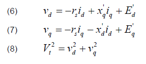
where: vd, vq : direct and quadrature axis stator terminal voltage components; Vt : generator terminal voltage; id, iq : direct and quadrature axis stator current components.
Distributed wind generation
Distributed wind generation contain many wind turbines and their detailed modelling may be unaffordable due to computational burden. In order to reduce the dimensionality, aggregation techniques are used to obtain equivalent models. A proper equivalent model can be easily obtained for fixed-speed wind turbines where a one-to-one correspondence between wind speed and active power output exists. In this case, aggregation is performed by adding the mechanical power of each wind turbine and by using an equivalent squirrel cage induction generator (SCIG) which receives the total mechanical power [14-15].
A simplified transient model of a SCIG can be described by the following algebraic-differential equations [16]:

Here, x’ = (xs + xm xr) / (xm + xr) is the transient reactance, Rs is the stator resistance which is assumed to be zero, xr is the rotor reactance, xm is the magnetizing reactance, x = (xs + xm) is the rotor open circuit reactance, T0‘ is transient open circuit time constant, Tm is the mechanical torque, S is the slip, Te = (Edr‘ Ids – Eqr‘ Iqs) is the electrical torque, Edr‘ and Eqr‘ are the direct and quadrature axis transient voltages respectively, Ids and Iqs are the direct and quadrature axis currents respectively, and ωs is the synchronous speed.
The DWG penetration level in the system is defined as [17]:

where PDWG and PCG are the amount of total active power generated by DWG and Centralized generation respectively.
Superconducting fault current limiter
Depending on the different superconducting materials and the operation principle the superconducting fault current limiters can be classified into different types [18]. In the resistive type the superconductor is directly connected in series to the line to be protected since in the inductive concept the superconductor is magnetically coupled into the line [19].
SFCL is a device that limits the fault current by generating impedance when a fault occurs. In addition, the limiting impedance generated to limit fault currents proves helpful in increasing generator output degraded by a fault, thus providing stabilization. as SFCLs installed in series with transmission lines can be just operated during the period from the fault occurrence to the fault clearing [7]. The equivalent circuit in π of the transmission line with SFCL is illustrated in Fig. 1, the associated equation for RSFCL can be described by exponentially expressed as follows.
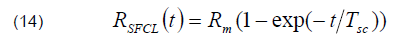
where, Rm is the expected maximum value of SFCL resistance in the normal state (Rm≈ 20 Ω), TSC is the time constant of transition from the superconducting state to the normal state, which is assumed to be 1ms. The One phase of the resistance SFCL model is simulated in MATLAB/Simulink as shown in Fig. 2.

Static Synchronous Compensator
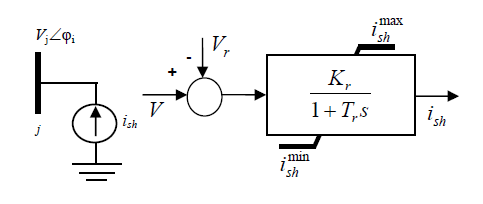
The Static Synchronous Compensator (STATCOM) is a shunt FACTS device that regulates the voltage of the ac bus to which it is connected. In the literature various STATCOM models have been developed and included within the load flow program, the optimal power flow and the transient stability analysis. A simplified STATCOM current injection model has been proposed in [20]. The STATCOM current ish is always kept in quadrature in relation to the bus voltage so that only reactive power is exchanged between the ac system and the STATCOM. The equivalent circuit and the control scheme are shown in Fig. 3 and undergoes the following differential equation:

where Kr is the regulator gain and Tr is the Regulator time constant.
The model is completed by the algebraic equation expressing the reactive power injected at the STATCOM node:

Simulation Results
To investigate the efficiency and the robustness of the proposed coordinated controller based SFCL and STATCOM on the power system transient stability enhancement in presence of distributed wind generation; the model is integrated in the IEEE benchmark four-machine two-area eleven bus test system in the case of three phase short circuit fault in the transmission line. DWG is connected to each of the load buses. The one line configuration is shown in Fig. 4.
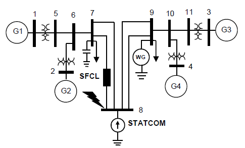
Technical data such as machine, voltage regulator, governor turbine, buses and branches information are taken from [21].
The transient stability is assessed by the criterion of relative rotor angles, using the time domain simulation method. The toolbox Sim Power Systems of MATLAB/SIMULINK software is used to carry out simulations studies.
Optimal Location Of SFCL–STATCOM
Optimal location and control of multi FACTS devices and multi SFCL is a vital and complex research area. In the literature many modern techniques and indices proposed for optimal location and control of multi FACTS devices. For secure operation of power systems, it is required to maintain an adequate voltage stability margin, not only under normal conditions, but, also, in contingency cases. In this study the voltage stability index using continuation power flow proposed for optimal location of STATCOM and SFCL.
From the continuation power flow results which are shown in the Fig. 5, the buses 5, 6, 7, 8, 9, 10 and 11 are the critical buses. Among these buses, bus 8 has the weakest voltage profile.

First, buses are classified based on three procedures: Procedure1: all buses are classified based on voltage stability index, the weak buses are identified based on voltage stability index, in this study, the bus 8 is considered as a candidate bus, the main role of the STATOM is to control voltage at this bus by exchanging reactive (capacitive or inductive) power with the network.
Procedure 2: Buses are classified based on the value of fault currents (three phase fault).
Procedure 3: Buses are classified based on the reactive power compensation witch consume by the DWG, the DWG will generate an active power, equal to the amount consumed by the load. However, in order to generate this necessary active power, the DWG need to consume reactive power from the network, the bus 9 is considered as the point of common coupling (PCC) where the WG is connected, the main role of the STATCOM is to compensate for this reactive power.
Impacts Of Combined SFCL–STATCOM Controller On Power System Transient Stability Enhancement
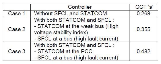
We have three logic Cases: Base case, which indicates the original system where there is no SFCL and STATCOM, in the system. Second case, with STATCOM at the weak bus (low voltage stability index) and SFCL at a bus which has high fault current. Third case, with STATCOM at the PCC and SFCL at another bus which has high fault current.
Case 1
A 3-phase fault is occurs at t = 1 second on line 7–8 near the bus 8 and it is cleared by opening the line at both ends. we consider a WG at bus 9 with a penetration level of 20 %. Generator 2 is the nearest generator to the fault location and therefore it has the most rotor speed deviation for this fault. The fault clearing time (FCT = 0.266 s) at first then (FCT = 0.300 s). Simulation results on the rotor angle differences of four generators without considering SFCL and STATCOM Controller are shown in Figs. 6.
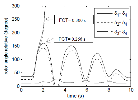
It can be seen that the relative rotor angles are damped and consequently the system maintains its stability, but when the fault clearing time increased to 0.300 s, the relative angles (δ14, δ24 and δ34) increase indefinitely, so at this critical situation the system loses its stability.
Case 2
In order to maximize voltage stability index and to improve power system transient stability, STATCOM located at the weak bus (low voltage stability index) and the SFCL is placed in line 7–8 which has high fault current. The STATCOM will try to support the voltage by injecting reactive power on the line when the voltage is lower than the reference voltage. The first mentioned fault in the previous sub-section is applied again.
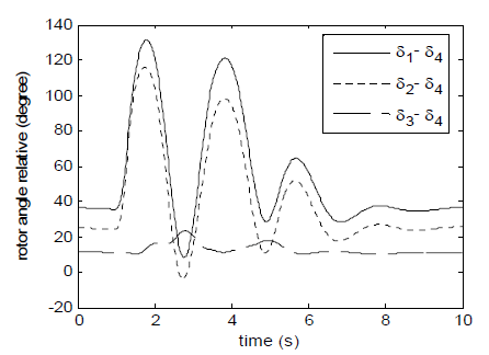
Time domain simulation performed at the cleared time 0.333 s, we can see from Fig. 8 the maximum relative rotor angles are (δ14 = 97°, δ24 = 91° and δ34 = 10°), the relative rotor angles (δ14, δ24 and δ34) are damped and therefore the system becomes stable compared to the first case (system unstable). The current on line 7–8 with SFCL is shown in Fig. 7.

In Fig. 9 it can be also seen that the system response with the SFCL-STATCOM is better than that with the with only STATCOM (Fig. 8) in the sense of the settling time is reduced. The critical clearing time is enhanced to a new value (0.355 s).
Case 3
In case 2 the SFCL is placed in the line 7–8 which has high fault current and the STATCOM located at the weak bus however in this case the STATCOM is placed at the PCC. The multipurpose becomes: reduce the current in line 7–8 (high fault current) and maximize dynamically voltage stability index, in this case the STATCOM compensate the reactive power consumed by the DWG and the fault current reduced by SFCL enhance the performance of the STATCOM (reduce saturation problem) dynamically during fault, and alternatively the required size of STATCOM will be reduced (economic aspect).

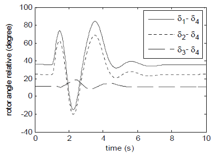
As a result, the reactive powers delivered by generating units reduce. Compared to the two others cases, the critical clearing time is improved. The SFCL is placed in line 7–8. The first mentioned fault in the sub-section (case 1) is applied again. The fault is cleared after 0.427 s.
In Fig. 10, It can be seen that the maximum relative rotor angles are (δ14 = 20°, δ24 = 18° and δ34 = 3°), the relative rotor angles (δ14, δ24 and δ34) are damped and therefore the system becomes stable compared to the first and second cases (system unstable). It can be also seen that the system response with the STATCOM at the PCC is better than that with the STATCOM at the weak bus in the sense of the settling time is reduced. The critical clearing time is enhanced to a new value (0.482 s). It is important to conclude that integration of shunt FACTS compensator (STATCOM) in coordination with SFCL in suitable location may help the system to improve the transient stability. Table 1 shows the values of margin stability (CCT) obtained corresponding to different cases.
Table 1. Margin stability (CCT) for different cases
Conclusion
Modern electric power systems’ operation, control and stability have been heavily affected by The rising penetration of energy sources renewal, increasing demands, restricted resources, and deregulated electricity markets power systems. In this study, the multi-machine power system transient stability improvement contains a large DWG via superconducting fault current limiter (SFCL) and shunt FACTS Controller (STATCOM) when applied through coordinated application was discussed and investigated. Simulation results performed on the IEEE benchmarked four-machine two-area test system in presence of distributed wind generation considering three phase short circuit clearly indicate that proposed combined controller placed at suitable locations can be used as an effective mean capable to enhance the margin stability and extend the critical clearing time in a multi-machine power system.
Future research will focus on investigation the effect of combined application of superconducting fault current limiter and other transient stability improvement FACTS devices in the presence of the distributed generation by considering the optimal value of SFCL and location of this hybrid Controller.
REFERENCES
[1] M. F. Farias, M. G. Cendoya, P. E. Battaiotto, Wind Farms in Weak Grids Enhancement of Ride-Through Capability Using Custom Power Systems, IEEE/PES Transmission and Distribution Conference and Exposition Latin America, pp. 1-5, 2008.
[2] A. Karami and S.Z. Esmaili, “Transient stability assessment of power systems described with detailed models using neural networks”, International Journal of Electrical Power and Energy Systems 45 (2013) 279–292
[3] L. Cong, Y. Wang, D.J. Hill.Transient stability and voltage regulation enhancement via coordinated control of generator excitation and SVC. Journal of Electrical Power and Energy Systems 27 (2005) 121–130
[4] R. You, M. H. Nehrir & D. A. Pierre, ” Controller Design for SVC and TCSC to Enhance Damping of Power System Oscillations”, Electric Power Components and Systems, Volume 35, Issue 8, pages 871-884, May 2007
[5] A.E. Hammad, “Analysis of power system stability enhancement by static var compensators”, IEEE Trans. PS 1 (4) (1986) 222–227.
[6] AL. Bettiol, A. Souza, JL. Todesco, JR. Tesch., “Estimation of critical clearing times using neural network. In: IEEE bologna powertech conference”, Bologna, Italy; 2003.
[7] M. Sjostrom, R.Cherkaoui and B.Dutoit, “Enhancement of power system transient stability using superconducting fault current limiters”, IEEE Trans. Applied Superconductivity, vol.9, no.2, pp.1328-1330, 1999.
[8] M. MAJKA, J. KOZAK, The Coreless Superconducting Fault Current Limiter 15 kV 140 A. Przegląd Elektrotechniczny, 92 (2016), no. 7, 38- 41
[9] K. Phorang, M. Leelajindakraireak, and Y. Mizutani, “Damping improvement of oscillation in power system by fuzzy logic based SVC stabilizer” Asia Pacific. IEEE/PES Transmission and Distribution Conference and Exhibition 2002, Vol.3, Oct. 2002, pp.1542–1547
[10] R. Ebrahimpour, E. K. Abharian, S. Moussavi, Z. & A. A Motie Birjandi, “Transient stability assessment of a power system by mixture of experts” International Journal of Engineering (IJE) Volume (4): Issue (1). pp. 93–104
[11] P. Kundur, “Definition and classification of power system stability IEEE/CIGRE joint task force on stability terms and definitions” IEEE Transactions on Power Systems, vol. 19, no.2, p. 1387-1401, May 2004
[12] N. ABU-TABAK, “Stabilité dynamique des systèmes électriques multi-machines: modélisation, commande, observation et simulation”, Doctoral Thesis, University of Lyon, 2008.
[13] I. GRICHE, S. MESSALTI , K. SAOUDI, Parallel Fuzzy Logic and PI Controller for Transient Stability and Voltage Regulation of Power System Including Wind Turbine. Przegląd Elektrotechniczny, 95 (2019), no. 9, 51- 56
[14] H. Arnaldo, Wind farm model for power system stability analysis, Doctoral Thesis, University of Illinois at Urbana- Champaign, 2010.
[15] A.Zebar, A. Hamouda and K. Zehar, “Impact of the location of fuzzy controlled static var compensator on the power system transient stability improvement in presence of distributed wind generation”, Rev. Roum. Sci. Techn. – Électrotechn. et Énerg., 60, 4, p. 426–436, Bucarest, 2015.
[16] Roy, Naruttam Kumar, M. J. Hossain, and H. R. Pota, Voltage profile improvement for distributed wind generation using DSTATCOM, IEEE Power and Energy Society General Meeting, 2011.
[17] M. Reza, PH. Schavemaker, JG. Slootweg, WL. Kling, L. Van Der Sluis, Impacts of distributed generation penetration levels on power systems transient stability, IEEE Power Engineering Society General Meeting, 2004.
[18] M. Noe, M. Steurer, “High-temperature superconductor fault current limiters: concepts, applications, and development status”, SUST 20 (2007).
[19] S. Nemdili and S. Belkhiat, “Electrothermal modeling of coated conductor for a resistive superconducting fault-current limiter”, J. Supercond. Nov. Magn. (2012). doi:10.1007/s10948-012- 1895-4
[20] F. Milano, Power System Modelling and Scripting, London: Springer, Aug. 2010.
[21] M. Klein, G. Rogers, Moorty and P. Kundur: “Analytical investigation of factors influencing PSS performance” , IEEE Trans. on Energy Conversion, vol. 7, no 3, pp. 382-390, September 1992.
Author: Dr. Abdelkrim. ZEBAR is with the Department of Electrical Engineering, Faculty of technology, and Ferhat Abbas Setif1 University, Setif, Algeria (corresponding author to provide phone: +213-776-87-72-46; e-mail: karimzebar@univ-setif.dz).
Source & Publisher Item Identifier: PRZEGLĄD ELEKTROTECHNICZNY, ISSN 0033-2097, R. 96 NR 11/2020. doi:10.15199/48.2020.11.33
