Published by Piotr PRUSKI, Stefan PASZEK, Silesian University of Technology
Abstract. In the paper, there is presented the analysis of disturbance waveforms of a synchronous generator operating in a single-machine power system consisting of a generating unit connected by a high-voltage power line to a bus. There are considered disturbances in the form of symmetrical and asymmetrical short-circuits in different places of the transmission line. The current-voltage equations of the power line and the bus are written for phase components, which allows for easy modeling of various asymmetries.
Streszczenie. W artykule analizowano przebiegi zakłóceniowe generatora synchronicznego pracującego w jednomaszynowym systemie elektroenergetycznym składającym się z zespołu wytwórczego, połączonego linią energetyczną wysokiego napięcia z siecią sztywną. Uwzględniono zakłócenia w postaci zwarć symetrycznych i niesymetrycznych w różnych miejscach linii przesyłowej. Równania prądowo-napięciowe linii energetycznej i sieci sztywnej zapisano dla składowych fazowych, co pozwala na łatwe modelowanie różnych asymetrii. (Analiza przebiegów nieustalonych w systemie elektroenergetycznym przy zwarciach niesymetrycznych).
Keywords: power system; generating unit; asymmetrical short-circuits; transient states.
Słowa kluczowe: system elektroenergetyczny, zespół wytwórczy, zwarcia niesymetryczne, stany nieustalone.
Introduction
Short-circuits are the most common and severe kind of faults occurring in the power system (PS). Most often they are asymmetrical short-circuits. Symmetrical short-circuits rarely occur in practice as compared with asymmetrical ones (only a few percent of the total number of cases). Over half of short-circuits in overhead high voltage lines are transient short circuits [1]. Asymmetrical PS operating conditions cause many unfavorable phenomena, i.a. in synchronous generators. It causes the necessity to limit the duration of such operating conditions [2, 3, 4].
Due to the difficulty in modeling asymmetrical operating conditions, symmetrical short-circuits are mainly analyzed in simulation investigations. Most specialized programs for the analysis of PS transient states allow for simulation of only symmetrical operating conditions. Therefore, it is reasonable to conduct research aimed at simulating the disturbance waveforms of selected quantities for different asymmetries occurring in PS. For this purpose, commonly used models of generating unit elements can be used, but some modifications should be introduced in them.
The analysis of asymmetrical PS operating states, including short-circuits, may help e.g. in better selection of power protection settings [5, 6]. The values and waveforms of different PS quantities may vary considerably depending on the type of the occurring asymmetry. Only effectively functioning protections can reduce the negative effects of disturbances, which allows reducing the consequences of faults occurring in PS.
The aim of the paper is a comparison and a harmonic analysis of the disturbance waveforms of selected quantities for different short-circuits with earth and clear to earth in a single-machine PS, consisting of a generating unit, a high-voltage transmission line and a bus. There was also analyzed the influence of the distance between the short-circuit location and the influence of including or neglecting effects of particular elements of the generating unit model.
Model of the analyzed PS
As a part of the conducted research, a mathematical model of the PS was developed in the Matlab-Simulink environment. In this model, using Configurable Subsystem blocks, it is possible to conveniently configure a specific model of the generating unit by selecting models of its individual elements.
In the carried out calculations, there were used: the GENROU [7, 8] synchronous generator model with subtransient asymmetry X”d ≠ X”q [3, 6, 9, 10] as well as the models of the static excitation system operating in the Polish Power System [7], the IEEEG1 steam turbine [7, 8] and the PSS3B system stabilizer [7].
When analyzing asymmetrical operating conditions of the PS, it is convenient to express the equations of stator currents and voltages, transmission line and bus with use of phase quantities. The Park transformation is used to relate the quantities in the d, q, 0 coordinate system to those in the phase A, B, C coordinate system [2, 3, 6, 7, 9, 10, 11, 12].
In the investigations, there were analyzed various asymmetries occurring in the transmission line. Fig. 1 shows a diagram of the analyzed PS for short-circuits with earth and clear to earth. On its basis, the model of the power line and the bus was developed.
Symbols in the figure: ij – generator stator currents (phase quantities, j = A, B, C), vj – generator stator voltages, vbj – bus voltages, Zj – complex impedances of the transmission line, Zsj, Zbj – impedance of the j-th phase line fragments during the short-circuit, Ifd – generator field current, vd – voltage between the neutral points of the generator and the bus, ibj – bus currents, vs – voltage at the short-circuit location, WG – generator neutral point ground switch.
This schematic diagram for short-circuits with earth (Fig. 1a) applies to both normal PS operation and a short circuit. In order to model a earth short-circuit in selected phases, one should assume zero voltages of the bus vbj in these phases and change the impedances of the line proportionally:
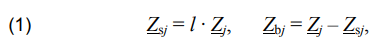
where: l – relative distance of the short-circuit location in the transmission line from the generating unit, in relation to the length of the whole line.
In connection with the assumed omission of transformation voltages [2, 6, 12], on the basis of Fig. 1, there were determined the algebraic relations between currents and voltages in the generator stator and transmission line equations. For healthy phases:
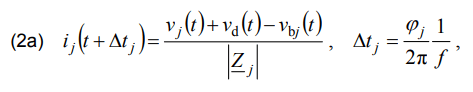
for phases short-circuited to ground:
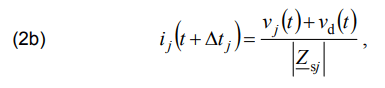
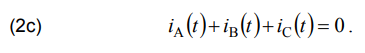
where: φj – phase angles of the particular transmission line impedances, f = 50 Hz. From (2a) and (2b) three equations were derived. In addition, for the system with ungrounded generator neutral point (open switch WG in Fig. 1a):
Using the generator stator axial voltages (output signals of the generator model and the generating unit model) and the axial voltages of the bus, it is possible to determine the phase voltages by the inverse Park transformation. Hence, from the system of equations (2), one can calculate four unknows: three phase currents and possibly the voltage vd at successive time instants. This is implemented in the developed model in the Matlab-Simulink environment. Using the formulas for the generator phase currents and Park transformation, the generator axial currents, being the input signals of the generator model and the generating unit model, were determined.
Fig. 1b presents a diagram for a 2-phase short-circuit clear of earth. The following equations determine algebraic relations between currents and voltages for this fault:
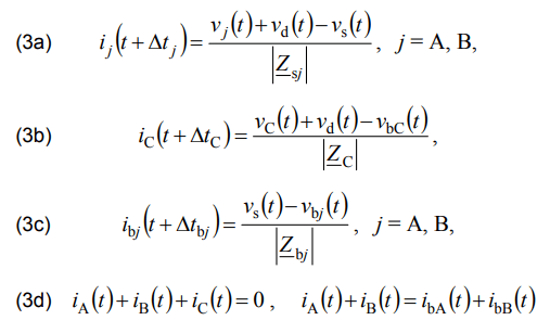
where: Δtj, Δtbj – time delays of the current waveforms, defined as in (2a); other symbols as in formulas (2).
From the system of equations (3) one can calculate seven quantities: five phase currents and voltages: vs and vd. The thus determined PS model is complete and allows for carrying out simulation calculations.
Exemplary calculations
In the calculations presented, the generator worked with grounded neutral point (closed switch WG in Fig. 1a, voltage vd = 0) in order to check an effect of the zero axial components of stator currents and voltages on the phase waveforms. In real high-voltage power systems, generators work usually with isolated neutral points.
In the first case, simulation calculations were performed for 3-phase short-circuits and 2-phase short-circuits with earth (in phases A and B) with a duration time equal to 0.15 s. There were analyzed short-circuits at different distances l from the generating unit for the generating unit with and without a PSS. It was assumed that in the steady state before the short-circuit, the generator was loaded with active power P0 = 0.5 p.u. and reactive power Q0 = 0.2 p.u.
Figures 2 and 3 show the waveforms (in relative units p.u. [4, 6, 7, 10, 11, 12]) of the angular speed deviation of the generator rotor Δω and the generator instantaneous power P in the analyzed cases, for different relative distance l from the generating unit.
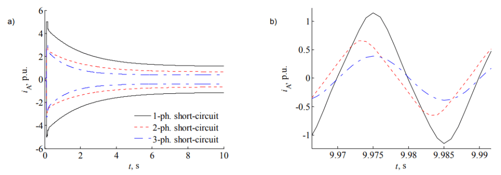
In the second case, there were analyzed long-lasting short-circuits: 1-phase with earth (in phase A), 2-phase clear of earth (in phases A and B) and 3-phase, at the distance l = 1% from the generating unit. In this case also breaks in the non short-circuited phases were assumed. In the steady state before the short-circuit the following load was assumed: P0 = 0.1 p.u. and Q0 = 0.05 p.u. The influence of the excitation system, the turbine and the PSS was neglected in this case.
Fig. 4 show the waveforms of stator current iA (in relative units) for the analyzed fault types.
Tab. 1 presents the harmonic amplitude distributions of the current in phase A, the voltage in phase C and the field current in the steady state of the short-circuit. The higher harmonics percentage values are given in relation to the first harmonic for the stator quantities, and in relation to the constant component for the generator field current. The reference values in relative units (p.u.) are given in brackets.
Conclusions
The calculations made allowed formulating the following conclusions:
• The use of the transmission line and bus model for the phase components of currents and voltages in the developed PS model allows for easy modeling of various symmetrical and asymmetrical short-circuits with earth and clear of earth, as well as breaks in individual phases of the transmission line.
• The disturbance waveforms of the analyzed quantities in the case of a two-phase short circuit with earth differ significantly from those for a three-phase short-circuit. During the two-phase short-circuit, the waveforms of the instantaneous power of the generator have components with relatively high frequencies (in comparison with the frequency of electromechanical swings). Such components do not occur under symmetrical operating conditions, including the three-phase short-circuit. After the short circuit, in each of the analyzed cases, the generating unit returns to symmetrical operation and only low-frequency components associated with electromechanical phenomena occur. After the three-phase short-circuit, the amplitudes of the deviations from the steady values of the waveforms, especially of the angular speed, are much larger than those after the two-phase short-circuit.
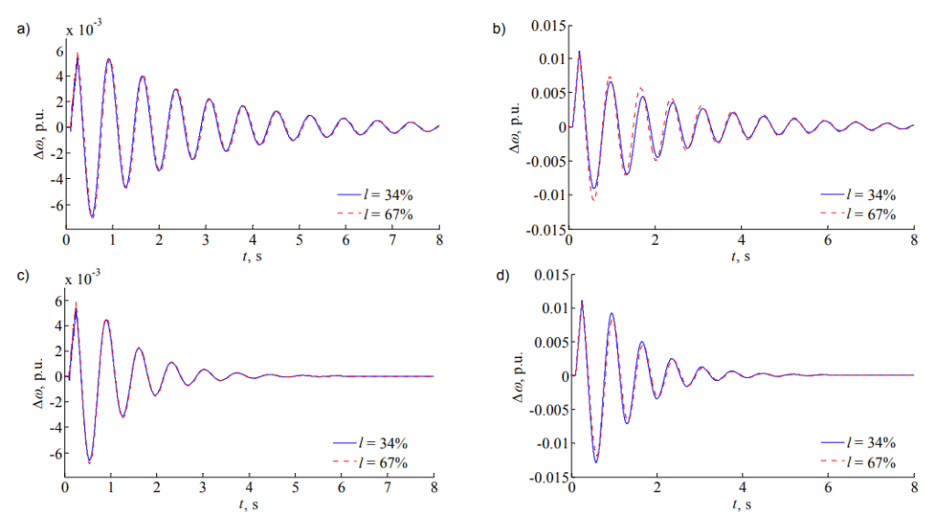
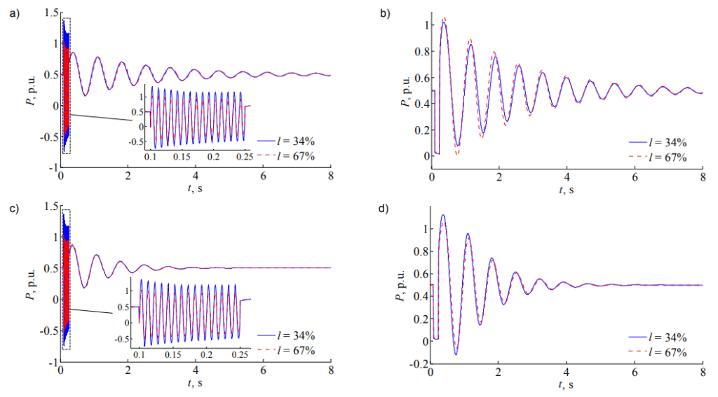
Table 1. Harmonic amplitudes of the analyzed quantities in the steady state

• The use of the PSS with appropriately selected settings allowed for significant increase in the damping of electromechanical swings in the PS. As a result, the angular stability of the PS improved significantly and the time needed to return to the steady state after the disturbance was shortened. In the analyzed cases, the PSS did not have a significant influence on the amplitudes of the deviations from the steady values of the waveforms during and immediately after the short-circuit.
• In the cases under consideration, the influence of the distance between the short-circuit location and the generating unit on the waveforms of the analyzed quantities is large only during the short-circuit duration. After the short-circuit, it is significant only in the case of the three-phase short-circuit for the system without the PSS, and in other cases it is negligible.
• The maximal amplitude of the generator long-lasting short-circuit current in the steady state occurs at the 1- phase short-circuit. The current amplitude in the steady state at the 2-phase short-circuit is higher than that at the 3- phase short-circuit. It complies with the synchronous machine theory [3, 13].
• In the cases of the asymmetrical short-circuits, odd higher harmonics with significant amplitudes occur in the steady state waveforms of the short-circuit current and the stator voltage on the non short-circuited phase. The generator field current in steady state includes a constant component and even higher harmonics. The harmonics distributions in the short-circuit current and the non short-circuited phase voltage are similar for both types of asymmetrical short-circuits. Only the third harmonic of the voltage at the 1-phase short-circuit has a much lower amplitude. The harmonics distributions in the field current are similar for the both types of asymmetrical short-circuits.
• At the 3-phase symmetrical short-circuit, the stator current and voltage waveforms includes practically only the first harmonic, and in the field current waveform only the constant component occurs. The generator subtransient asymmetry does not cause the occurrence of higher harmonics in case of the machine symmetric operation. The presented power system model is also used in other investigations. They focus on various RL and XT-type synchronous generator models [7, 8] taking into account or neglecting the stator transformation voltages, with different input and output signals. A further extension of the model is planned.
REFERENCES
[1] Kacejko P., Machowski J, Zwarcia w systemach elektroenergetycznych [Short-circuits in power systems] (in Polish), WNT, Warszawa, 2009
[2] Concordia Ch., Synchronous Machines. Theory and Performance, John Wiley & Sons, Inc., New York, 1951
[3] Boldea I., Synchronous Generators, Taylor & Francis, 2015
[4] Pyrhonen J., Jokinen T., Hrabovcova V., Design of Rotating Electrical Machines, Wiley & Sons, Ltd, 2008
[5] Ungrad H., Winkler W., Wiszniewski A., Protection techniques in electrical energy systems, Mercel Dekker Inc., New York 1995
[6] Machowski J., Bialek J., Bumby J., Power System Dynamics. Stability and Control, John Wiley & Sons, Chichester-New York, 2008
[7] Paszek S., Berhausen S., Boboń A., Majka Ł., Nocoń A., Pasko M., Pruski P., Kraszewski T., Measurement estimation of dynamic parameters of synchronous generators and excitation systems working in the National Power System (in Polish), Monograph No. 504, Wydawnictwo Politechniki Śląskiej, Gliwice, 2013
[8] Boboń A., Paszek S., Pruski. P., Kraszewski T., Bojarska M., Computer-aided determining of parameters of generating unit models basing on measurement tests, Przegląd Elektrotechniczny, 5 (2011), pp. 17-21
[9] Berhausen S., Boboń A., Determination of high power synchronous generator subtransient reactances based on the waveforms for a steady state two-phase short-circuit, Applied Mathematics and Computation, 319 (2018), pp. 538–550
[10] Wang X., Song Y., Irving M., Modern Power Systems Analysis, Springer Boston, MA, 2008
[11] Krause P., Wasynczuk O., Sudhoff S., Pekarek S., Analysis of Electric Machinery and Drive Systems, third ed., Wiley-IEEE Press, 2013
[12] Gao J., Zhang L., Wang X., AC machine systems, Mathematical Model and Parameters, Analysis, and System Performance, Springer-Verlag, Berlin-Heidelberg, 2009
[13] Krause P.C., Analysis of electric machinery, McGraw-Hill, 1986
Authors: dr inż. Piotr Pruski, E-mail: Piotr.Pruski@polsl.pl, prof. dr hab. inż. Stefan Paszek, E-mail: Stefan.Paszek@polsl.pl, Politechnika Śląska, Wydział Elektryczny, Instytut Elektrotechniki i Informatyki, ul. Akademicka 10, 44-100 Gliwice.
Source & Publisher Item Identifier: PRZEGLĄD ELEKTROTECHNICZNY, ISSN 0033-2097, R. 96 NR 2/2020. doi:10.15199/48.2020.02.05
