Published by Amina DJABOREBBI, Boubakeur ZEGNINI, Djillali MAHI, Amar TELIDJI University of Laghouat, PoBox 37 G, Mkam Laghouat 03000, Algeria.
Abstract. The paper deals with transient analysis of grounding systems wind turbines. To improve the accuracy of lightning impact studies on wind power grid generation, it is necessary to develop faster, more accurate simulation tools and to use increasingly sophisticated models .First, we identify and characterize the different parameters that influence the behaviour of grounding systems, particularly when they broadcast a lightning current. To do this, an electromagnetic model from the theory of antennas equation’s by – Euler method with incorporating soil ionization allows to represent the behavior of an earthing system in the frequency domain.. Different configurations with several complexity degrees have been simulated. To validate the obtained results, we compare our TLM results to the measurement results and FDTD simulation. A comparison between two different configurations of wind turbine grounding systems with comparing the transient potential, impulse impedance, and DC component of transient impedance between the two configurations when buried in soil. A number of illustrative computational examples are presented in the paper.
Streszczenie. W celu poprawy dokładności badań wpływu wyładowań atmosferycznych na produkcję energii wiatrowej konieczne jest opracowanie szybszych i dokładniejszych narzędzi symulacyjnych oraz wykorzystanie coraz bardziej wyrafinowanych modeli. W pierwszej kolejności identyfikujemy i opisujemy różne parametry wpływające na zachowanie się systemów uziemienia, zwłaszcza gdy przekazują one prąd piorunowy. W tym celu opracowany został model elektromagnetyczny z teorii równań Eulera z wykorzystaniem jonizacji gruntu, który pozwala na przedstawienie zachowania się systemu uziemienia w dziedzinie częstotliwości. Symulowane są różne konfiguracje o kilku stopniach złożoności. W celu walidacji uzyskanych wyników, porównujemy nasze wyniki TLM z wynikami pomiarów i symulacji FDTD.Porównanie dwóch różnych konfiguracji uziemienia turbiny wiatrowej z porównaniem potencjału przemijającego, impedancji impulsowej i składowej stałej impedancji przemijającej pomiędzy tymi dwiema konfiguracjami, gdy są one zakopane w gruncie. (Modelowanie odpowiedzi na prąd piounowy w uziemionym systemie turbiny wiatrowej)
Keywords: Grounding system, Transmission line method, Finite difference time domain, Soil ionization, Transient behaviour,
Słowa kluczowe: System uziemienia, metoda linii transmisyjnej, domena czasowa różnic skończonych, jonizacja gleby.
Introduction
The grounding systems transient behavior was the object of several investigations, specifically their transient response when subjected to lightning current, either by experiments [1] or by numerical simulations. The numerical simulations are based principally on three main theories: Field calculation using Finite Element Method [2], Field calculation using Antenna Theory Methods [3,4,5] or by using Transmission Line Modeling (TLM) [6, 7, 8, 9]. Some electrical elements are characterized by their high length like high voltage towers and wind turbines. Since the lightning strokes are attracted by high-rise buildings [10], many recent studies have been presented to the show the transient behaviour of high voltage line towers [5, 11, 12] and Wind turbine grounding systems [4, 13] when subjected to lightning current.
In our case, we are interested to the protection of wind turbines against the lightning strokes, and this by evaluating the transient response of their grounding systems, because that numerous wind turbines have been placed in regions characterized by high activity of lightning [14], and that turbines contains a very sensitive electronic components which control several systems like the convertors and pitch angles controller. So, their grounding systems are designated to avoid the lightning current to the ground without damaging its components [15]. In many investigations, the grounding systems are modeled using TLM theory because of its simplicity and effectiveness with giving results in good accordance with the other theories and the experimental results [6, 7, 16, 17, 18]. And this method has been implemented in several simulation programs like MATLAB and EMTP.
Zalhaf et al. [19, 20] have simulated the transient behavior of the whole wind turbine connected to grounding system using MATLAB. The investigation has been continued by another one [21], in which the simulations by MATLAB have been compared with some experimental results and other simulations results obtained by PSCAD/EMTDC software. A good accordance has been obtained. Several studies in the same subject have been published which using ATP-EMTP code. Sekioka et al. [22] have used ATP-EMTP to study the perturbations generated by the grounding systems subjected to lightning current, where they have studied the induced overvoltages in the surrounding of wind turbines grounding systems. Using the same code, Pastromas et al. [23] have simulated the wind turbine grounding system to present the current distribution in different segments. The grounding system of offshore wind turbine farms have been studied too by ATP-EMTP code, Heng et al. [24] have simulated the proposed tower model to evaluate the transient voltage obtained when injecting lightning current.
The TLM has been solved by FDTD method in [15]. In their investigation Raju et al. have studied the impact of soil parameters and distance between wind turbines on the transient response of grounding systems installed in homogeneous soil. In their simulation, the soil ionization haven’t been considered. For another configuration of wind turbine grounding system, the frequency variation of impedance has been studied by Sunjerga et al [13] with Antenna Theory by using NEC-4 Code. In this investigation, the transient response and soil ionization haven’t been evoked.
Senthilkumar et al [25] have used CDEGS software to study the grounding potential rise in ground grid buried in multilayer soil when subjected to power frequency current. In precedent investigation [17] we have used TLM to simulate several grounding system configurations and to study the optimal configuration for grounding system. The results have shown that the grid configuration always gives the lowest transient impedance. In another investigation [18] we have used the same model based on TLM to study the transient behavior of grounding grids buried in homogeneous and in heterogeneous soil. In the investigation we have studied the influence of the grid dimensions, the kind of the ground and the current injection point on the grounding system response (transient potential and impedance). The obtained results show that the grid containing the greater number of conductors permits to obtain the lowest transient potential and impedance.
This investigation treats the modeling of grounding system using TLM equation solved by – Euler method with incorporating soil ionization. Different configurations with several complexity degrees have been simulated. To validate the obtained results, we compare our TLM results to the measurement results and FDTD simulation ones. The novelty of our paper consists in a comparison between different wind turbine grounding configurations, and this comparison is made for grounding systems buried in homogenous and heterogeneous soil. After choose the best configuration, we study the current and the potential along the chosen grounding configuration when buried in homogeneous and stratified soil, to evaluate the components participation in the transient response, and this to authors’ knowledge haven’t been studied before. A comparison between two different configurations of wind turbine grounding systems with comparing the transient potential, impulse impedance, and DC component of transient impedance between the two configurations when buried in homogeneous and stratified soil. Finally, we choose the best configuration and we study the transient current and potential along this configuration when buried in homogeneous and stratified soil, and we give some discussions in the conclusion.
Transmission line method and soil ionization
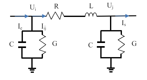
The transient currents are characterized by high frequency components, for this the study of the systems subjected to lightning currents requires the use of some methods takes into configuration the electromagnetic wave propagation in the studied systems [8, 18]. Since it has improved its effectiveness for the modeling of such phenomena, the transmission line has been adopted to be used in this investigation for simulating the transient response of grounding system [17, 18]. It consists of divide every grounding conductor into several segments. Each segment is modeled by transmission line as shown in Fig. 1. The longitudinal part represents heat losses and magnetic effect of the conductor, and the transversal parts are modeling the heat losses and the polarization in the soil surrounding the electrode.
For a grounding conductor buried in soil of resistivity ρs and permittivity εs and permeability μs and subjected to current of frequency f, the current wavelength λ can be determined by the formula [6]:
These parameters are calculated for each segment of grounding grid according to [26] by the formulas for the horizontal conductors:
And for the vertical conductor the parameters become [26]:
where ρc is the soil resistivity, ρs is the soil resistivity, l is the length of the electrode, h is the radius of the electrode, h is the burial depth, r is conductor radius, μ is the soil permeability (4πx10-7 (H/m)), εr is relative permittivity, and ε0 is the vacuum permittivity (8.859×10⁻¹² F/m).
When the current Ie is injected, we determine in each segment of grounding system: The input voltage Ui, the branch current Iij, the output voltage Uj and the output current Is. These parameters are shown in Fig.2.
By applying Kirchhoff laws, we determine the next differential equations:
These equations are valid only for one segment, and the output current and voltage of this segment will be the inputs of the next segment.
These equations and the other ones of rest of grounding electrode segments are solved by using iterative methods. In our simulation we have used Euler one.
To incorporate soil ionization, the transversal conductance is considered time dependent parameter G(t) determined from G and calculated by [7]:
With I(t) is the injected current and Ig is current is the current from which the soil ionization initiates in the soil which determined from soil electrical critical field. This later has been determined by [27]:
For this; the equations (10) and (12) become:
The TLM simulation is validated if every conductor segment length will be smaller than one tenth of wavelength (∆l≪λ /10) [6].
Simulation Results and validation
The proposed model has been already validated by comparing with ATP-EMTP results in previous investigation [17, 18].
In [28], Visacro et al. have make some experiments on horizontal electrode buried in homogeneous soil and subjected to impulse current. The chosen electrode is of 12 m length and 7 mm radius buried at 0.5 m depth. The electrode is buried in two different kinds of soil: the first is high resistivity soil (4 kΩ.m) and the second is low resistivity soil (300 Ω.m).
The soil permittivity has been considered 20. The current injected is of 2 A peak value. The authors of [28] have simulated the same configurations using their developed Hybrid Electromagnetic Model based on Antenna Theory. Their obtained results are presented on the Fig. 3.

We have estimated the injected current, and we have used this current to simulate the same configuration with same soil and conductor parameters. Our obtained results for this simulation are shown in Fig. 4.
When comparing our TLM results and those obtained by Hybrid Electromagnetic Model [28] with the experimental results, we observe that the voltages computed using our TLM are clearly show better agreement with the experimental voltages compared to those obtained using the proposed [28]. We note the existence of a difference doesn’t exceed 10%.

After validating our TLM calculation with comparing with experimental result, we validate our method for more complicated configuration of grounding system. We study the response of wind turbine grounding system.
We study the transient behavior of the grounding system composed of two squares of 12m x12 m (ring earth) and 6m x 6m (foundation reinforcing) co-centered buried at 2 m depth. The squares are related by two conductors placed as cross (bonding bar). The extremities of extern square are related to 10 m vertical electrodes (points 1, 2, 3 and 4) as shown in figure 5. The conductor radius has been considered 10 mm.
The current injected in the center has been considered of 50 kA magnitude and 0,25 μs front time.

This configuration has been studied by [15] using FDTD method.
For our study, we will simulate this configuration in two cases: the first one with ignoring soil ionization, and the second with considering the soil ionization. The configuration has been evaluated for two soil resistivity values namely 1000 Ωm and 2000 Ωm and the relative permittivity has been considered 9. Our obtained results for TLM with ignoring soil ionization phenomenon are presented in figure 6 while the potentials obtained with incorporating of soil ionization are shown in Fig. 7.
When confronting our TLM potentials presented in Fig. 6. to those obtained by [15], we note a good accordance with the potentials obtained using FDTD method [15], and this accordance validates our TLM simulation. When incorporating soil ionization phenomena, we note a great decrease on the transient potential (about 25% for 2000 Ω.m and 10% for 1000 Ω.m), while the waveform has been kept for the two cases. So, the incorporation of soil ionization in TLM simulation causes a significant potential decrease. When the soil is more resistive, the potential will be significantly reduced which means that the soil ionization phenomena must be considered for the grounding systems buried in resistive soil.
After validation of the simulation of grounding system presented in Fig.5., we simulate here another configuration of wind turbine grounding system. We name the configuration presented in Fig. 5. by Configuration A, and the second configuration that we will study by configuration B which is presented in the Fig. 8.

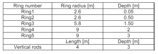
The grounding system of configuration B consists of several rings connected with several rods. The geometrical parameters are presented in Table 1 where the rings (such like r2 shown in figure 8) and the depth of each ring are noted.
Table 1. The Geometry of the wind turbine grounding system B
In this part, we will inject the same impulse current into the two configurations. The current formula is given by i(t) = 10 (e-27000t – e-5600000t ). Three soil parameters have been considered of resistivity/relative permittivity values: 10Ωm/80, 100Ωm/40 and 1000Ωm/9.
We note that for both configurations A and B, the conductor radius value has been considered 7 mm. The obtained results for the configurations A and B are shown in Fig. 9: (a) for grounding systems buried in soil of resistivity 10Ωm and relative permittivity 80, (b) for soil of resistivity 100Ωm and permittivity 40 and (c) for the grounding systems buried in soil of resistivity 1000Ωm and permittivity 9. We note that for all of the configurations and for any soil parameters, the principal variations are observed between 0 and 4 µs. After that, the potential becomes approximately constant, that means that after 4 µs the impedance becomes constant.
Discussions
In the three tests, we observe on the figures 9 (a), (b) and (c) that the configuration B gives the lower values of transient potential all of the soil resistivity values:
– For the soil resistivity/permittivity 10Ωm/80 the peak value of configuration B present 58% comparing to the one obtained for the configuration A.
– When the soil resistivity/permittivity are 100Ωm/40 the peak value of configuration B present 62.5% comparing to the peak value of the potential obtained for the configuration A.
– When the grounding systems are buried in soil of resistivity/permittivity 1000Ωm/9, the transient potential waveshape has been changed, and many oscillations have appeared for the both potentials.
In this case the configuration B gives lower transient potential when comparing to the configuration A with a difference of 70% noted between the potential peaks.
We note that for the configuration A, when increasing soil resistivity, the wave shape of the potential becomes different to the current one. For high resistivity values (1000Ωm/9), the potential contains significant oscillations.
We define the impulse impedance Zp by the ratio of peak voltage Vp to peak current Ip.

We define the DC component of the transient impedance by the ratio of the constant value of potential (In this case, the potential value after 4 µs) to the current peak.
We present the impulse impedance of each configuration (A and B) and for the all of soil resistivity on the Table 2, and the DC component of the transient impedance on the Table 3.
Table 2. The impulse impedance values for each configuration

The Table 2 presents show the configuration B gives the lowest impulse impedance when comparing to the values obtained for the configuration A. So, we can adopt that the configuration B which contains more rings distributed on several levels can reduce the transient impedance.
Table 3. The DC component of transient impedance values for each configuration
From the Table 3, we can see that the DC component of each configuration increase linearly with the increasing of soil resistivity, so this DC component is a constant depend to the grounding system geometry multiplied by the soil resistivity.
When comparing DC components of configurations A with B, we observe that the DC component of A is the triple of the one of B. So, the configuration B gives the lowest DC component of transient impedance. We note that for high resistivity soil, the impulse impedance becomes equal to the DC component of transient impedance.
Conclusion
We first identified and characterized the different parameters that influence the behaviour of earthing systems, especially when they diffuse a lightning current. The resistivity is the most important element in the design of grounding systems. When its value is very high, the potential generated by an atmospheric discharge becomes important. Next, a model was described to represent the transient behaviour of the grounding systems in the frequency domain. To do this, we are based on the electromagnetic model. This model based on the antennas, uses the numerical method known as Euler by using two applications .The first application was the incorporating soil ionization in the model of wind turbine grounding systems. A potential decrease is noted when incorporating soil ionization phenomena, however the waveform has been kept. The second application was a comparison between two wind turbine grounding systems; the first is the one which has been validated with FDTD simulation composed by two squares co-centered buried at same depth, and related to long vertical electrodes, and the second is another configuration composed of five rings disposed on several depths and connected to short vertical electrodes.
We note that for high resistivity soil, a remarkable voltage oscillation appears on the transient potential, and its waveform becomes different to the current one.
We have evaluated the DC component of the transient impedance; it consists of ratio between voltage stabilized value and the current peak one. This component may be determined by a constant which depend to the system geometry multiplied by soil resistivity.
Finally, our model also allowed us to estimate the temporal responses of the wave electromagnetic created by the grounding system on its material environment and propose optimization solutions for more resistive flooring.
REFERENCES
[1] H. Rochereau,: Response of earth electrodes when fast fronted currents areflowing out. EDF: Buletin de la Direction des Etudes et Recherches B, (2), 1988, pp. 13–22
[2] M. Akbari, K. Sheshyekani and M. R. Alemi,”The Effect of Frequency Dependence of Soil Electrical Parameters on the Lightning Performance of Grounding Systems,” in IEEE Transactions on Electromagnetic Comptibility,vol.55,no.4, pp.739-746,Aug.2013.
[3] D. Poljak, S. Sesnic, S. V. Tkachenko, K. El KhamlichiDrissi, K. Kerroum, “Time Domain Analysis of the Horizontal Grounding Electrode: Antenna theory approach versus transmission line approximation,” Proc. of the 2014 International Symposium on Electromagnetic Compatibility (EMC Europe 2014), Gothenburg, Sweden, 181-185, September 1-4, 2014.
[4] R. Araneo, G. Lovat, S. Celozzi and P. Burghignoli. Numerical Analysis of Mutual Transient Voltages in Grounding Systems of Offshore Wind Farms. International Applied Computational Electromagnetics Society Symposium (ACES). 2018.
[5] Javad Gholinezhad, and Reza Shariatinasab .Time Domain Modeling of Tower-Footing Grounding Systems based on Impedance Matrix. IEEE Transactions on Power Delivery. Volume: 34, Issue: 3.2019 PP : 910 – 918.
[6] Yang L, Wu G N, Cao X B, “An optimized transmission line model of grounding electrodes under lightning currents,” Sci China Tech Sci, Vol. 56, 335-341, 2013.
[7] Daniel S. Gazzana, Arturo S.Bretas, Guilherme A. D. Dias,Marcos Telló, Dave W. P. Thomas and Christos Christopoulos.The Transmission Line Modeling Method to Represent the Soil Ionization Phenomenon in Grounding Systems. IEEE transactions on magnetics, vol. 50, no. 2, February 2014.
[8] Daniel S. Gazzana, Guilherme A. D. Dias, Roberto C. Leborgne, Arturo S. Bretas,Marcos Telló, DaveW.P. Thomas, Christos Christopoulos. Novel Formulation to Determine the Potential on the Soil Surface Generated by a Lightning Surge. ieee transactions on magnetics, vol. 52, no. 3. march 2016
[9] M. Mokhtari, Z. Abdul-Malek and Z. Salam. An Improved Circuit-Based Model of a Grounding Electrode by Considering the Current Rate of Rise and Soil Ionization Factors. IEEE Transactions On Power delivery, vol.30, no. 1, pp:211-219. February 2015
[10] IEC. Protection Against Lightning Part 1: General Principles. IEC 62305-1, Ed. 1.0b, 2006
[11] W. R. SI, C. Z. FU, T. Y. WU, S. J. Wang, P. YUAN. Measurement and Analysis of Impulse Grounding Impedance for UHV Transmission Tower. IEEE International Conference on High Voltage Engineering and Application (ICHVE) 2016
[12] Amauri G. Martins-Britto, Sébastien R. M. J. Rondineau and Felipe V. Lopes. Transient Response of the Grounding Grid of a Power Line Tower Subject to a Lightning Discharge. Workshop on Communication Networks and Power Systems (WCNPS). 2018
[13] Antonio Sunjerga , Quanxin Li , Dragan Poljak , Marcos Rubinstein , Farhad Rachidi. Transient Impedance of Interconnected Wind Turbine Grounding Systems 26th International Conference on Software, Telecommunications and Computer Networks (SoftCOM) 2018
[14] D. Cavka, D. Poljak, V. Doric, and R. Goic, “Transient analysis of grounding systems for wind turbines,” Renew. Energy, vol. 43, pp. 284–291, 2012.
[15] Md. Raju Ahmed and Masaru Ishii. Electromagnetic Analysis of Lightning Surge Response of Interconnected Wind Turbine Grounding System. 011 International Symposium on Lightning Protection (XI SIPDA), Fortaleza, Brazil, October 3-7, 2011.
[16] Yaqing Liu, Mihael Zitnik, and Rajeev Thottappillil, “An Improved Transmission-Line Modelof Grounding System,” IEEE Transactions on Electromagnetic Compatibility, VOL. 43, No. 3, 348-355, AUGUST 2001.
[17] Djaborebbi Amina, Boubakeur Zegnini, Tahar Seghier ,Hamza Gueffaf, Djillali Mahi. Economic optimization of copper conductor for transient response of grounding system. 5TH International Conference On Advances In Mechanical Engineering Istanbul 2019, 17-19 DECEMBER 2019.
[18] DJABOREBBI Amina, ZEGNINI Boubakeur, SEGHIER Tahar, Mahi Djillali. Evaluation and Performance of Grounding Grids Buried in Soil Under Impulse lightning Current. The First International Conference on Communications, Control Systems and Signal Processing.16-17 March 2020 El-Oued, Algeria
[19] A. S. Zalhaf, Mahmoud Ahmed, S. Ookawara and Mazen Abdel-Salam. Computation of Transient Induced Voltages along a Wind Turbine Struck by Lightning. 2nd International Conference on Power and Renewable Energy 2017.
[20] A. S. Zalhaf, Mahmoud Ahmed, S. Ookawara and Mazen Abdel-Salam. A Simplified Model of Wind Turbine for Lightning Transient Analysis as Influenced by Structure of Grounding System. 5th International Conference on Electric Power and Energy Conversion Systems (EPECS) 2018.
[21] Amr S. Zalhaf, Mazen Abdel-Salam, Diaa-Eldin A. Mansour, Shinichi Ookawara, Mahmoud Ahmed. Assessment of wind turbine transient overvoltages when struck by lightning: experimental and analytical study. IET Renewable Power Generation Volume: 13, Issue: 8 .Year: 2019 . PP 1360 – 1368
[22] Shozo Sekioka, Hitomi Otoguro, and Toshihisa Funabashi. A Study on Overvoltages in Windfarm Caused by Direct Lightning Stroke. IEEE Transactions on Power Delivery ( Volume: 34 , Issue: 2 , April 2019 )pp : 671 – 679.
[23] S. A. Pastromas, K. Maimaris, I. K. Stasinos, I. A. Naxakis, E. C. Pyrgioti. Assessment of Wind Turbine Grounding System. IEEE International Conference on High Voltage Engineering and Application (ICHVE) 2018
[24] Lu Heng, Xia Nenghong, Qian Chao and Tian Jianlin. Modeling of Offshore Wind Turbine Under Lightning Stroke and Analysis of Impact Factors on Transient Overvoltage. 11th Asia-Pacific International Conference on Lightning (APL) 2019.
[25] R.T.Senthilkumar, K.Selvakumar and K.Nagarajan. Optimization of Multilayer Earth Structure by using Steepest Descent Method and Estimation of Transient Ground Potential Rise in Substation. 2018 IEEE PES Asia-Pacific Power and Energy Engineering Conference (APPEEC)
[26] Sunde ED, “Earth Conducting Effects in Transmission Systems,” New York, N. Y.: Dover publications, Inc.; 1968.
[27] T.K. Manna, P. Chowdhury. Generalized equation of soil critical electric field Ec based on impulse tests and measured soil electrical parameters, IET Generation, Transmission and Distribution. 1 (5) (2007) 811-817.
[28] Silvério Visacro, Wyllian L.F. Pinto, Fuad S. Almeida, M.H. Murta Vale, Gláucio Rosado. Experimental Evaluation Of Soil Parameter Behavior In The Frequency Range Associated To Lightning Currents. 29th International Conference on Lightning Protection 23rd – 26th June 2008 – Uppsala, Sweden
Authors: Amina Djaborebbi, Laboratoire d’études et développement des matériaux semi-conducteurs etdiélectriques(LeDMaScD), Amar Telidji University of Laghouat. ,PoBox 37 G, Mkam Laghouat 03000,Algeria E-mail:a.djaborebbi@lagh-univ.dz, prof dr Boubakeur Zegnini , LeDMaScD, Amar Telidji University of Laghouat. ,PoBox 37 G, Mkam Laghouat 03000,Algeria,E-mail: b.zegnini@lagh-univ.dz, prof dr Djillali Mahi , LeDMaScD,Amar Telidji University of Laghouat. ,PoBox 37 G, Mkam Laghouat 03000,Algeria,E-mail: d.mahi@lagh-univ.dz
Source & Publisher Item Identifier: PRZEGLĄD ELEKTROTECHNICZNY, ISSN 0033-2097, R. 97 NR 2/2021. doi:10.15199/48.2021.02.33
