Published by Bartosz DOMINIKOWSKI, Politechnika Łódzka, Instytut Systemów Inżynierii Elektrycznej. ORCID: 1. 0000-0002-4762-2005
Abstract. Differential amplifiers in measuring systems are often exposed to external factors, which may lead to disturbance of their proper operation. Due to the capabilities of microprocessor systems, the intelligent algorithms work well in systems for diagnosing circuit errors such as a short circuit or a circuit break. A group of switches is connected to the primary circuit which are designed to check the condition of the measurement system branches. If an error is detected, the measurement of voltage is switched to the additional system.
Streszczenie. Wzmacniacze różnicowe w układach pomiarowych często narażone są na czynniki zewnętrzne, które mogą doprowadzić do zaburzenia ich prawidłowej pracy. Ze względu na możliwości układów mikroprocesorowych algorytmy inteligentne sprawdzają się systemach diagnostyki błędów obwodowych takich jak zwarcie lub przerwa obwodu. Do obwodu podstawowego dołączono grupę przełączników, które mają za cel sprawdzić stan gałęzi systemu pomiarowego. W przypadku wykrycia błędu pomiar przełączany jest na tor dodatkowy. (Inteligentny nadmiarowy tor pomiarowy z wykrywaniem błędów toru podstawowego).
Słowa kluczowe: detekcja błędów, wzmacniacz, algorytm inteligentny.
Keywords: error detection, amplifier, intelligent algorithm.
Introduction
The development of electronic components makes more and more demands on measuring systems regarding their static, dynamic and quality properties. Diagnostics of analog circuits includes fault detection, which consists in verifying whether the measuring system functions in accordance with the design assumptions. In the event of a failure, the diagnostic system indicates the location of the damaged elements along with identification of the type of failure. Identification of the damaged element provides the measuring system the important information during its operation. Many fault diagnostic methods have been discussed in the references [1-3]. The mathematical analysis of analog systems, due to the tolerance of individual elements of the measurement system, is a problem of failure testing (data error). Analog measurement systems have a great advantage over digital converters of the measured value due to the possibility of selecting parameters such as the range and speed of the processed signal by selecting the appropriate component. Such systems with parameters matched to the measurement appear in industrial applications. Analogue measurement technique often uses special differential operational amplifiers to process the voltage signal from a measure and converter (e.g. a low Ohm resistance shunt). This circuit amplifies the signal and provide a high impedance to the signal source. These systems allow to the measurement of the voltage difference between the given measuring points. Such an electronic circuit is often used in traction batteries to measure the voltage on a single cell. Many integrated amplifier circuits can be found in industrial electronics. Often their measurement error is minimal. These systems cannot be easily monitored for additional fault monitoring circuit. Therefore, in systems with high measurement reliability, circuits composed of individual elements (outside the integrated structure) should be designed. All the resistance elements of the amplifier circuit exposed on the outside of the integrated circuit are able to monitor of their operation. Additional fault monitoring circuits in the differential amplifier are connected to its nodes. Amplifiers are often internal protected. Which means that the circuits connected to it are most often damaged. An example of protection for amplifier circuits is given in [4]. The loss of measurement information due to an open or short circuit in the measurement system can lead to failure of the entire monitored measurement circuit. In measuring systems in electric vehicles, this is a significant problem due to the energy transmission between the energy storage. Incorrect measurement information can damage the electric energy storage system in vehicle’s electrical.
Damage of electrical systems is often divided into repairable and non-repairable. The stream of damage in the differential amplifier circuit may change its structure, which leads to the malfunction of the entire system. Some configurations of the differential amplifier obtained as a result of a failure cannot be distinguished from its correct operation based only on signals measured at the its input and output. In such a situation, the only possibility of maintaining the measurement of the input signal is appropriate damage detection and the use of an additional measurement system.
Often the voltage signal is measured in the dangerous conditions such as: flammable gases, dust, vibroacoustic, high or low temperature and high humidity. Such environmental parameters may have influence on the failure of the measurement system. Failure of the measuring system operating in such an environment may consist in: short-circuit or breakage of a branch of the electrical circuit, change in the resistance of the resistors operating in it or damage the amplifier. The external factors that can cause a fault consisting in shorting the resistor is silver migration. Accidental galvanic connection of circuits operating close to each other may short-circuit the branches. The break in the circuit with the resistor may be caused by a sulfur containing atmosphere (which results in the production of silver sulfide) or corrosion. Other causes of a circuit break with a resistor are high mechanical stress, which causes solder cracks or connecting the measuring system to too high voltage (electrical breakdown of the element) and electrical overloads. Elements working in the measuring system are related to the aging process and change of their nominal parameters. The above-mentioned problems are the reason for equipping the measuring circuit with an additional circuit. Many fault of resistors have been discussed in the references [5, 6].
Materials and Methods
Due to the complex problem of electrical device failure detection, the mathematical description or circuit analysis of the failure do not give good results. The author of the article designed a system for detecting unrepairable errors. In the analyzed measuring system of the differential amplifier, all voltage nodes are available for measurements. To check the functionality of the measuring circuit, the author of the article used additional switchable circuits activated with a given time interval.
A given section of the electrical circuit can:
• conduct electricity (branch operational),
• do not conduct electricity (the same voltage operate at its ends) – (state without failure),
• be open or shorted (branch failure).
The diagnostic system of the branch circuit of the differential amplifier is shown in Figure 1. This system consists of two resistors (amplifier resistor: R1,…, R4 and measuring RM1,…, RM4) and a DC voltage source Vcc. During the measurement of the correctness of the operation the branch differential amplifier the input signal source (V1, V2) and the output should be disconnected. In this aim the switch A11, A31, A22 should be opened. At the same time, the voltage measurement is switched to the additional (redundant) measuring system. The values of the resistors RM1, …, RM4 are selected so that the measurement of the signal from them should be not a problem for systems measuring the voltage from them. The measured value from RM1, …, RM4 are sent to the input of the intelligent algorithm. The test circuit works is divided into parts:
• Disconnecting the electric branches (l1, l2, l3, l4– Figure 1) from the amplifier (OA– Figure 1) by switches (marked in Figure 1 with the symbol A);
• Connected to branches ends the DC voltage source (Vcc – Figure 1) with a resistor (RM1, …, RM4 – Figure 1) by switches (marked in Figure 1 with the symbol B) for the duration of measurement test time.
During the circuit test, a resistive voltage divider is created which is supplied by the voltage Vcc. The values of the individual elements are equal: all RM=10kΩ, R1=R2=R3=R4=25kΩ.
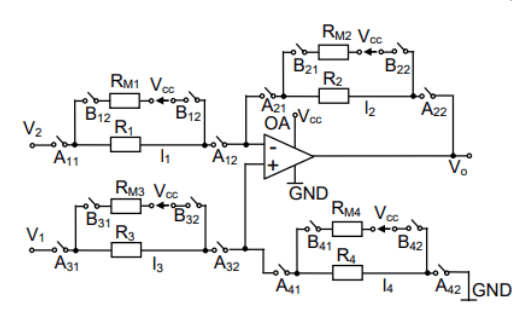
The analog circuits operating in the proposed system for monitoring the parameters of a branch of the differential amplifier should have a large frequency band. This is important because failures can change quickly. Measurement errors can occur in the test circuit of the differential amplifier. For this reason, the author of the article corrected the obtained data by a program. As a result, the voltage values during diagnostics on the measuring resistors RM1,…, RM4 can only have three values: 0V, 1,42V, 5V depending on the conductivity state of the electric branch. The voltage supplying the circuit with measuring resistors RM1,…, RM4 is Vcc = 5V and comes from the power supply of the amplifier. The operational amplifier working in a differential system was chosen as zero-drift, zero-crossover. The operational amplifier is supply by voltage stabilized. The maximum current for testing the correct operation of the differential amplifier circuits is 2mA. To measure the voltage from measuring resistors (RM1,…, RM4), the author of the article used integrated amplifiers with high input impedance. These amplifiers implement a gain factor of 1 V/V and are available two in one integrated circuit. These systems are also powered from the same voltage stabilizer with the output voltage parameter Vcc.
The proposed solution, with the diagram shown in Figure 1, guarantees detection of a circuit failure in a measurement system using a differential amplifier. Reliability of detection of errors in the operation of the differential amplifier depends on the installation the additional test circuit. The most accurate results are obtained by connecting the monitoring circuit between the start and the end of point the amplifier branch.
Data from the series resistor (RM1,…, RM4– Figure 1) are transferred to the microprocessor, which are analyzed by the Fuzzy Neural Network implemented in it. The selection number of input signals of the intelligent algorithm is related with the optimization of the diagnostic system operation. Information about a failure in the differential amplifier circuit is important for the monitored circuit. The above data may indicate problems which could damage the main circuit. An example is the short-circuit of a certain part of the main circuit through the measuring system by a differential amplifier. This situation can change the configuration of the main circuit connection.
The author of the article selected 66 failure states of the differential amplifier circuit branch and entered them into a table which is used for learning Fuzzy Neural Network. Above-mentioned table contains 4 columns and 67 rows filled with values for three operating states of the individual electric branches of the differential amplifier and is storage in the file. Depending on the operating status of the branch, there may be three different voltage values in the system: working properly (1,42V), open (0V) or shorted (5V) circuit. A Fuzzy Neural Network (FNN) was used to create a database of faults in the differential amplifier circuits. The advantages of using neural fuzzy systems are their mathematical ability to represent linguistic rules. This allows them to be used for: estimation, identification and classification tasks.
Fuzzy rules contain membership functions composed of many parameters. Often their exact values are unknown. System ANFIS (Adaptive Network Fuzzy Inference System) – allows to build a fuzzy model with parameters selected by the neural network. Fuzzy Neural Networks can provide high efficiency in solving the problem of failure detection of a differential amplifier circuit. The author of the article used a model of Takagi-Sugeno Kang (TSK) fuzzy neural network in the differential amplifier damage detection system. In the TSK model, the premises of the fuzzy rule are fuzzy, while the conclusion uses functional dependencies. The purpose of the Fuzzy Neural Network in the measurement system is to indicate only the place and type of failure (hidden in one number), so the polynomial characterizing the conclusion of the rule is zero order (constant number). Such a simplified model of intelligent network layer allows for minimizes the calculations performed by the microprocessor. Because the above-mentioned the intelligent network is designed for faults monitor of four branch circuits of the differential amplifier, the fuzzy rule can be written as follows: R(i): IF (VRm1 is A1) AND (VRm2 is A1) AND (VRm3 is A1) AND (VRm4 is A1), THEN y=c. Signals in the premises of the rule (VRm1, VRm2, VRm3, VRm4) are the voltage drops across resistors in additional fault detection circuits of the differential amplifier circuits. The value of this voltage drop indicates the type of damage (break, short circuit) or its absence in a electric branch. The intelligent network is implemented in structure with a multi-input (input vector – IN) and one output. The output of this intelligent algorithm is a value varying from 0 to 66 which related with a given fault in the differential amplifier circuit. For example: the failure of the circuit l1 (see Figure 1) consisting in a break, the system measures the values of voltage drops on individual measuring resistors (RM1,…, RM4) and writes the obtained values to the input network vector IN = [0 1,42 1,42 1,42]T (IN=[VRm1 VRm2 VRm3 VRm4]T , where: T– vector transposition). The intelligent network generates an output signal equal 11. In time of the test circuit the measurement of input voltage (V1-V2) is switch on the additional measurement circuit and the error report is generated for the system user. A fragment of the failure states of the circuit the differential amplifier branch is shown in Table 1.
Table 1. Table of failure states in the differential amplifier circuit

Line 2 (n = 1) in Table 1 corresponds to failure-free (input1=1,42V, input2=1,42V, input3=1,42V, input4=1,42V, IN=[1,42 1,42 1,42 1,42]T ) of operation the differential amplifier branch with an output of intelligent network equal 0. Each other line in Table 1 indicates failure operation of a branch of the differential amplifier and is coded by number in the sixth column.
Transformed into a neural network the fuzzy model diagnosing circuit errors of the differential amplifier system consists of several layers of neurons:
• input – the input values of the network coming from the circuits testing the operation of the differential amplifier branch which are written to the vector IN;
• the first hidden layer – responsible for fuzzification the input values of the IN vector in the linguistic values of the fuzzy rules. Elements of this layer intelligent network contain functions of membership of the input vector IN according to µA(VRm1), µA((VRm2), µA((VRm3), µA((VRm4);
• second hidden layer – the activation level of the fuzzy rule is compute. Neurons from this layer perform the function of the t-norm in the form of an algebraic product (π) for the kth rule which is determined by the relationship [7]:
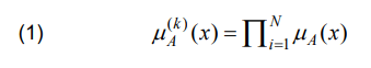
where: i– iteration, N– number of input variables, k– kth rule of inference, A – fuzzy set;
• defuzzification – sharpening of the output variable from network which representing fault of the differential amplifier is defined by the relationship [7]:
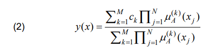
where: y(x) – the output value of the neural fuzzy network, ck– constant value in fuzzy rule conclusion, M– number of inference rules, k– kth rule of inference.
The fuzzy neural network is built in Matlab program by using the Fuzzy Logic Toolbox. This network has four input variables and one output variable. To build fuzzy rules, Gauss membership functions were used by the following relationship [8]:
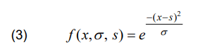
where: x-input variable, σ– width (responsible for the shape of the function), c– fuzzy set center.
Information about the Fuzzy Neural Network is presented in [9-11]. Figure 2 shows the functions of belonging to the input space of the intelligent algorithm after the learning process.
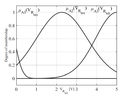
The circuits testing the operation of individual branches of the differential amplifier are identical with the values of the resistors working in the amplifier (R1, .., R4, RM1, …, RM4) and the value of the supply voltage Vcc. The membership function parameters for each input variable of the neural fuzzy network are parameters identical. Appropriate data are required for the learning and testing process of the fuzzy neural network. This values has been defined in the file in the form of a table. The number of intelligent network input variables cannot be too large because the model of the differential amplifier diagnostic system becomes very complex in time and computation. Complicated models are not suitable for operate on the microprocessor system. If the same number of membership functions N is assigned to each input variable x (voltage values from the resistors Rm1, …, Rm4 – Figure 1) of the fuzzy network model, then the maximum number of rules of the proposed system is obtained on the basis of the dependence NX . In the case of the proposed neural fuzzy system, for each input variable x = 4 (four branches of the differential amplifier) three membership functions were given, which gives 81 rules. With an increase of the size of the input vector, the number of rules of the neural fuzzy system increases exponentially. The advantages of the fuzzy neural network are:
• its elements are connected in a legible manner,
• use of the measurement data (all failures of the differential amplifier circuits) to teach it,
• the possibility of interpreting the network as a fuzzy model by using the rules in the expert notation: “if the input is – then the output is”. Such a fuzzy rule indicates exactly the type of failure and its place of occurrence.
Results
The proposed system of redundant circuit with failure detection of the differential amplifier was designed and tested in the Matlab/Simulink simulation program. For its verification, the author of the article used rectangular input functions presented in Figure 3 a), b), c) and d).
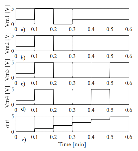
These functions (Figure 3 a), b), c), d)), were generated by forced failure states in a given branch of the differential amplifier (see Figure 1). Respectively for a given time interval, the operation of the diagnostic system is as follows:
• time interval from t=0 to 0,1s (see waveform Figure 3 a), b), c), d)), input vector IN=[1,42 1,42 1,42 1,42]T , answer of the intelligent system y=0 (see waveform Figure 3 e)). This information means that all branches of the differential amplifier are working properly. The data is listed in Table 1 (row number 2, n=1);
• time interval from t=0,1 to 0,2s (see waveform Figure 3 a), b), c), d)) the input vector IN= [5 5 5 5]T system response y=1 (see waveform Figure 3 e)). This information means that there is a fault in the circuits of the differential amplifier consisting in shorting the all resistors (R1,.., R4). The data is listed in Table 1 (row number 3, n=2);
• time interval from t=0,2 to 0,3s (see waveform Figure 3 a), b), c), d)) the input vector IN= [0 0 0 0]T system response y=2 (see waveform Figure 3 e)). This information means that there is a failure in the circuits of the differential amplifier consisting in opening the all resistors (R1,.., R4). The data is listed in Table 1 (row number 4, n=3);
• time interval from t=0,3 to 0,4s (see waveform Figure 3 a), b), c), d)) the input vector IN= [1,42 0 0 0]T system response y=3 (see waveform Figure 3 e)). This information means that the branch l1 of the amplifier is working correctly, while the rest of the branch of the differential amplifier has a break in the circuits. The data is presented in table 1 (row number 5, n=4);
• time interval from t=0,4 to 0,5s (see waveform Figure 3 a), b), c), d)) the input vector IN= [1,42 0 0 5]T system response y=4 (see waveform Figure 3 e)). This information means that the amplifier branch l1 is working properly. The error appeared in branch: l2 and l3 (break) and a short circuit in l4. The data is listed in Table 1 (row number 6, n=5);
• time interval from t=0,5 to 0,6s (see waveform Figure 3 a), b), c), d)) the input vector IN=[1,42 0 5 0]T system response y=5 (see waveform Figure 3 e)). This information means that the branch l1 is working correctly. The error appeared in branch: l2 and l4 (break), and short circuit in l3. The data are listed in table 1 (row number 7, n=6).
The intelligent algorithm was checked by computer testing by forcing all failure states. The obtained data confirmed the effectiveness of the proposed algorithm.
Discussion
Redundant systems are used in dangerous measurements or industrial conditions. Such systems create reliable measurement systems. Systems based on intelligent techniques better map the shape of the assumed system characteristics. The proposed algorithm correctly diagnoses circuit faults of the differential amplifier. Due to the external environmental conditions, the use of monitoring systems for the correct operation of the measurement system is metrologically important.
REFERENCES
[1] Gizopoulos D., Advances in Electronic Testing: Challenges and Methodologies; Springer: Dordrecht, The Netherlands, (2006)
[2] Kabisatpathy P., Barua, A., Sinha S., Fault Diagnosis of Analog Integrated Circuits; Springer: Dordrecht, The Netherlands, (2005)
[3] Fault-Diagnosis Systems: An Introduction from Fault Detection to Fault Tolerance, Springer, (2006)
[4] Daniel Miller, Nick Scandy, Op Amp ESD Protection Structures, Texas Instruments Incorporated, (2020)
[5] Michael Reid Maurice N. Collins Eric Dalton Jeff Punch David A. Tanner, Testing method for measuring corrosion resistance of surface mount chip resistors, Microelectronics Reliability, Volume 52, Issue 7, July (2012), 1420-1427
[6] Michael Reid, Jeff Punch, Claire Ryan, John Franey, Gustav E. Derkits, Jr., William D. Reents, Jr., Luis F. Garfias The Corrosion of Electronic Resistors, IEEE Transactions on Components and Packaging Technologies, VOL. 30, NO. 4, DECEMBER 2007
[7] Stanisław Osowski, Sieci neuronowe do przetwarzania informacji, Oficyna Wydawnicza Politechniki Warszawskiej, (2006)
[8] Andrzej Piegat, Fuzzy Modeling and Control, Springer, (2001)
[9] Maria Mrówczyńska, Approximation abilities of neuro-fuzzy networks, Geodesy And Cartography, Vol. 59, No 1, (2010), 13-27
[10] Mrówczyńska, M., Gil, J. System neuronowo-rozmyty w zastosowaniu do badań deformacji konstrukcji Mrówczyńska, Czasopismo Techniczne. Środowisko (2008), R. 105, z. 2-Ś, 215-221
[11] Dudek G. Neuro-fuzzy approach to the next day load curve forecasting, Przegląd Elektrotechniczny, R. 87 NR 2, (2011) 61-64
Autorzy: dr inż. Bartosz Dominikowski, Politechnika Łódzka, Instytut Systemów Inżynierii Elektrycznej, ul. Stefanowskiego 18, 90-537 Łódź, E-mail: bartosz.dominikowski@p.lodz.pl.
Source & Publisher Item Identifier: PRZEGLĄD ELEKTROTECHNICZNY, ISSN 0033-2097, R. 98 NR 12/2022. doi:10.15199/48.2022.12.53
