Published by Szymon ROGOWSKI1, Maciej SIBIŃSKI2, Karol GARLIKOWSKI3,
Katedra Przyrządów Półprzewodnikowych i Optoelektronicznych, Politechnika Łódzka,
ORCID. 1. 0000‐0002‐1279‐3592, 2. 0000‐0002‐9752‐3400
Abstract. The following article presents results of measurements and parameter comparison of energy bank based on supercapacitor batteries and a typical lead-acid solution designed for PV microinstallation. For the purposes of the research, basic measurements of the charging and discharging characteristics of the energy storage consisting of 10 supercapacitors were carried out. Then this set was adopted as an energy storage system in a typical off-grid photovoltaic installation, which was launched and tested with the use of various types of loads in a static and dynamic conditions.
Streszczenie. Poniższy artykuł przedstawia wyniki pomiarów oraz porównania baterii superkondensatorów oraz typowego rozwiązania kwasowoołowiowego dla magazynowania energii w instalacji PV. Na potrzeby badań przeprowadzone zostały pomiary podstawowych charakterystyk ładowania i rozładowywania magazynu energii składającego się z 10 superkondensatorów. Następnie tak przygotowany zestaw został zastosowany jako układ magazynujący energię w typowej instalacji fotowoltaicznej typu off-grid, która została uruchomiona i przebadana z wykorzystaniem różnego rodzaju obciążeń w warunkach statycznych i dynamicznych. (Zastosowanie superkondensatorów w instalacjach fotowoltaicznych)
Słowa kluczowe: instalacja PV, superkondensatory, akumulatory, instalacja off-grid, żywotność
Keywords: PV installation, supercapacitors, batteries, off-grid installation, service life.
Introduction
One of the most important elements influencing the off-grid or hybrid photovoltaic installations lifetime is the energy storage system, which is considered to be the element with the shortest lifetime. In order to increase the operating time of the entire installation, and at the same time to improve its efficiency, it is necessary to extend the work time of the storage elements. Currently, the most commonly used elements for storing energy produced by a photovoltaic installation are lead-acid batteries or the increasingly popular lithium-ion cells. The advantage of lead-acid batteries is a relatively low price per unit of power, however, this solution has a very big disadvantage, which is a small number of charging and discharging cycles and high sensitivity to external parameters, including ambient temperature. Additionally, installations based on gel or AGM batteries do not allow for high currents charging and discharging cycles. The elimination of these obvious conventional energy storages limitations can increase the efficiency and profitability of the entire installation, and additionally extend the failure-free operation time without the need to replace the energy supply.
One of the ways to eliminate problems with the limitations of the charging and discharging currents is to use elements that are not current-sensitive up to level of several dozens of amps. Such solution may be supercapacitors, which are characterized by the long-term stability with operation currents exceeding 100 A and excellent dynamics. In addition, their use can also extend the working time of the entire storage system, owing to much greater number of charging and discharging cycles, which according to the manufacturer’s data, may exceed one million [1-3].
This article will present the results of research on the use of supercapacitors as energy storage elements in a typical PV off-grid installation and, additionally, their comparison with conventional AGM batteries.
Supercapacitors and typical energy storage operation.
Energy storage is a process whose purpose is to preserve electric energy and allow it to be used at another point in time. In the case of photovoltaic installations two most important applications may be indicated. Firstly off-grid installations, where there is no connection to the power grid, and secondly hybrid solution where it is important to increase the household consumption of energy produced by the installation. In this case also temporary stabilization of local grid is an important issue to be addressed. Currently, the most commonly used energy storage systems in PV installations are constructed with:
• Gel batteries,
• AGM (Absorbed Glass Mat) batteries.
The biggest advantage of the first type of batteries is that they may successfully withstand cyclic operation, making them suitable for off-grid installations, and they are practically maintenance-free. Unfortunately, despite the above advantages, the use of electrolyte in the form of a gel has some disadvantages, the greatest of which is the low power value during high current discharge and the significant influence of the ambient temperature on their capacity. Despite these disadvantages, structures of this type are the most frequently chosen solutions used as energy storage for photovoltaics, which is mainly due to the wide range of available products and the low price. AGM technology batteries are characterized by higher values of current and power in the short discharge event which results from the low internal resistance. In addition, they also have a high level of energy concentration and more effectively remove the heat generated during the current flow comparing to the gel solutions. Unfortunately, apart from the above advantages, AGM batteries are characterized by the shortest operating time, amongst all batteries made in lead-acid technology which results in the lowest number of charging and discharging cycles. A very big limitation in the operation of this type batteries is their high sensitivity to deep discharge, which demands the usage of specialized charge regulators. [4-6].
Comparison of described batteries basic parameters is presented in Table 1.
Regardless of the type, each conventional energy bank is characterized by a relatively small number of charging cycles which significantly reduces operation time. A way to extend life of the energy bank is to use elements that are characterized by much better cyclic parameters and resistance to very high currents. Supercapacitors can be components meeting the above criteria.
Supercapacitors can be placed between batteries and dielectric capacitors. They can store up to 200 times more energy than standard batteries and release it with much more power, while maintaining the current density typical for capacitors [8]. They owe their properties to special structure of electrodes which are made of activated carbon in the form of nanotubes, obtaining huge active surface of over 3000 m2/g and high electrical conductivity. The energy is stored in the micropores of the electrode material and in the space between them and the electrolyte. The process of recovering energy delivered during charging is very effective reaching the efficiency of 96-98% [9-12,17].
Table 1. Basic parameters of exemplary PV system batteries[7,8]

We can divide supercapacitors in several ways. The first is the division according to the principle of operation and charge accumulation. We can distinguish:
• Double layer electrochemical capacitors,
• Pseudocapacitance capacitors (redox capacitors).
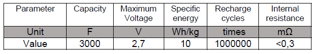
Regardless of the type of supercapacitors, they have many properties that don’t have typical batteries. One of the greatest advantages of supercapacitors is a very large capacity of up to 3000 F, which, combined with a very short charging and discharging time, allows for very high power densities. Typical values for this parameter range from 1 kW/kg to 10 kW/kg [1,10,13]. Very short charging and discharging time of supercapacitors results from a very low internal resistance, the value of which, is about 0,3 mΩ, which is 10 times smaller than typical value for a lead-acid battery However their greatest advantage over typical solutions is a very large number of charging and discharging cycles, which according to the experiments can even exceed a million.
Apart from the advantages supercapacitors also have some pretty significant drawbacks that limit their capabilities for direct use as energy storages. One of the greatest is the low energy density stored in comparison to conventional solutions, which is only 20 Wh/kg. The average value for a gel batteries is about 3,5 times greater. Typically it is about 70 Wh/kg [7,8,10,11]. Very significant problem when using supercapacitors as alternatives to conventional batteries creates the shape of the voltage during discharging process. When drawing energy from a standard battery, the voltage remains practically constant until the total discharge, when it drops sharply. In case of capacitors, from the beginning the voltage drop takes an exponential shape, which forces the use of much better control systems.
The last parameter limiting the operation of supercapacitors in energy storage systems is the relatively low permissible voltage, which is typically 2,7 V for a single element. Exceeding this value may cause the phenomenon of electrolysis when large amounts of gases are generated that can lead to an explosion of the capacitor. One way to increase the operating voltage of a group of superacapacitors is to connect elements in series. Such a procedure allows to achieve voltages at any level, unfortunately it is associated with a reduction of the resultant capacity of the entire system.
Thanks to their properties, including resistance to environmental conditions, very long service life and low service requirements, supercapacitors may be very interesting solution for storing energy produced from photovoltaic installations.
Purpose of research
The article presents a solution that allows to extend the working time of PV installation energy storage systems by using supercapacitors in their construction. The main purpose of the research is to construct and test an energy storage built on the basis of supercapacitors. Thanks to the use of their greatest advantages, such a solution can significantly extend the working time of the energy storage. An additional purpose is to confirm the the possibility of using such energy bank with the standard off-grid inverter.
One of the basic assumptions of the research is to check whether the battery built on the basis of supercapacitors is suitable for direct use as an energy storage for a commercial PV inverter. In order to verify the efficiency and profitability of this system a special analysis will be carried out to estimate the amount of charge collected and consumed during the typical operation of the entire system. As an additional element of the research temperature measurements were made to check how the charging and discharging processes affect this parameter, and consequently, the safety of the proposed solution.
Methods and experiments
The research carried out for the purposes of this article was divided into two stages. The first stage was aimed at determining the operation parameters of the supercapacitors and batteries and was performed using DC voltages. In the second stage the complete PV system equipped with mixed energy storage bank was constructed and investigated by DC and AC analysis.
Measurements of supercapacitors and batteries
To build energy storage series connection of 10 supercapacitors BCAP3000P by Maxwell Technologies was used [16]. The need to use as many as 10 elements resulted from the minimum voltage suitable for inverter input which was equal to 24 V DC.
The parameters of used supercapacitors are presented in Table 2.
Table 2. Basic parameters of supercapacitors BCAP3000P [1]
Firstly the basic parameters of supercapacitors were measured including charging and discharging characteristics. Such measurements allowed to predict how ready battery set would work, when consisting of several supercapacitors connected in series and what would be the differences compared to typical batteries. Additionally, owing to these measurements, it is be possible to calculate the actual capacity of the prepared bank, as well as to check how relatively large values of incoming and outgoing currents will affect the supercapacitors.
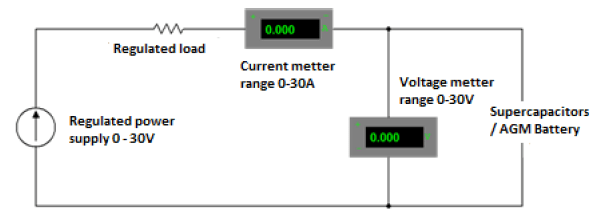
To determine the characteristics of the supercapacitor and AGM battery, the measuring system, which scheme is shown in Figure 2 was constructed.
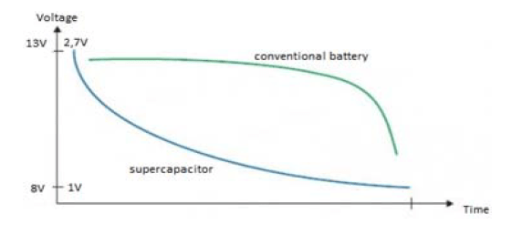
Initially the determination of the charging and discharging characteristics of supercapacitors was performed. It was carried out to check how these elements cooperate when connected in series. For proper operation of this setup a special safety box was designed and a set of balancers was attached for parameters equalization. The results of the research are presented in the figure 3.

The shapes of the charging and discharging curves are very similar to what we can find in the literature [9]. The charging process was carried out for a relatively low starting current of 20 A, so as to observe the voltage distribution on individual supercapacitors. As we could see during both of these processes, the voltage on individual elements changed in a very similar way, which means that they were charged and discharged evenly.
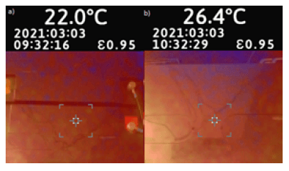
At the time of both characteristics measurements, the surface temperature of supercapacitors was monitored, using a Fluke VT04 Visual IR Thermometer. The temperature in the room where the measurements were taken was kept at a constant level of 22,5°C.
As we can see in figure 4, during the charging of supercapacitors, there was a slight increase of their surface temperature resulting from the processes taking place inside them [9]. The observed difference is relatively small, which during standard use will not significantly affect their work. The same measurement was done during the discharge process, but in this case the difference was 0,1°C, which can be considered a measurement error. Similar studies were performed for much higher currents. Their results were analogous, namely, there was small temperature increases during the charging process.

In order to compare supercapacitors with typical AGM batteries basic charging and discharging characteristics for them were also verified. The results are shown in Figure 5. As in the case of supercapacitors, it was necessary to adjust the voltages of the energy storage to the inverter level, therefore the characteristics and further tests were performed for 2 AGM28 12/65 batteries connected in series.

As we can see, the shapes of the curves are completely different than in the case of supercapacitor batteries. During the process of discharging the voltage at the terminals remained practically at the same level. The difference between the initial and final voltage during the charging process in the case of an AGM battery was only 3%, while in the case of supercapacitors the difference is almost 100% which corresponds to the information that can be found in the literature [4].
During discharge measurements, the load was changed in order to observe the voltage shape, which was marked on the diagram. As can be seen, with a lower value of the current drawn from the battery, there was a slight increase in the voltage at the terminals, which does not occur in the case of supercapacitors which is visible, for example, in the picture 7. A sudden voltage drop should be noticed only at the time of a very deep discharge, which is a disadvantageous phenomenon for this type of energy storage, therefore it has not been presented in the above characteristics. During the charging process, is visible a constant voltage value at the terminals, while the current decreases with time. This phenomenon is a typical solution when charging chemical cells [3,4].
Comparing the characteristics of batteries and supercapacitors, we can see a big difference between them, which unfortunately may have a negative impact on the possibility of using the second ones with typical inverters, because we will only use a small part of the stored energy.
As for the supercapacitor batteries, was also measured the temperature of the AGM battery during charging and discharging. The results are presented below in figure 6.
As we can see, there is a much higher temperature rise during charging a battery than with supercapacitors. The difference between the initial and final temperature in this case is as high as 4,4°C, whereas for capacitors this difference was only 0,4°C. This temperature change is the result of chemical reactions taking place inside the electrolyte and on the surface of the electrodes during the charging process, which produces heat as a side effect [4].
A similar measurement was made during the discharge process, however, in this process, there were no noted temperature changes as in the case of supercapacitors.
As we can see when measuring the temperature for both types of energy storages, its increase is noticeable, but it is not large enough to affect the safety of any of the magazines. In this aspect, supercapacitors operate much better because in their case the difference before and after charging was 10 times smaller than that of a lead-acid battery.
The next step in preparing supercapacitors to work in a typical installation was to calculate the amount of energy that they are able to store in such a configuration. For this purpose we can count the charge accumulated in the supercapacitor battery in a following way:
Q = C・U
Where: Q – accumulated charge, C – capacity of supercapacitors, U – voltage across capacitors.
Q = 8100 C
Using the dependence that 1 Ah = 3600 C, we can calculate that 2,25 Ah is stored in the entire supercapacitor package. This means that this value is several times smaller than the capacity of typical lead-acid batteries. For comparison, the two batteries connected in series used for earlier measurements had a capacity of 65 Ah.
Measurements of a working PV installation
After proper preparation and protection, the supercapacitor store was connected to the inverter, which was then loaded with various types of receivers in order to observe the behavior of the energy bank during frequent and sudden load changes and to check the actual amount of energy that we are able to extract from it.
The performed measurements were made using a PV installation, which the block diagram is presented in Figure 7.
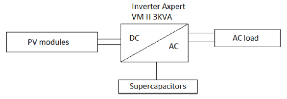
The installation consists of 7 polycrystalline photovoltaic modules SH-250P6-20, which parameters are presented in Table 3.
Table 3. Basic parameters of modules SH-250P6-20 [18]

In addition, the entire system includes an inverter Axpert VM II 3KVA, which basic parameters are presented in Table 4.
Table 4. Basic parameters of inverter Axpert VM II 3KVA [19]
The first load measurements were made in the evening hours, when there was no generation from the connected PV installation. During these measurements, various loads were connected to the AC output of the inverter. Additionally in the inverter setup the battery cut-off value was set to 21 V. The example shape of the voltage at the supercapacitor terminals and the outgoing current are presented in the Figure 8.
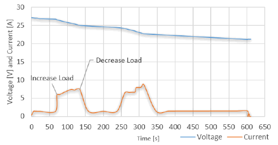
The discharge process was performed with the use of a variable load, started twice. The first start-up took place around 70 seconds, which is visible in the diagram by an increase in the current drawn from supercapacitors. The increase in the consumed current during the first switching on results from the type of operation of used load. The device was turned off for about 140 seconds, which is visible as a decrease the current consumption to about 1,5 A. A similar process was performed in approximately 240 second and completed after 80 seconds. The remaining time during which the current is consumed at the level of about 1,5 A is the state in which the receivers were completely disconnected and the consumed energy only supplied the inverter. After about 10 minutes, the system was turned off because the voltage at the battery terminals dropped to about 21 V, which is the safety limit implemented in the inverter. As a result of such operation of the system, we are not able to use all the energy stored in the supercapacitors, but only a small part of it. The value of energy, consumed by the load is only Q = 1843 C, which when converted to Ah gives only 0,51 Ah. This means that, we can only use about 23% of the energy stored in supercapacitors. Such a small value significantly affects the economic aspect of this solution. To increase the efficiency, it may be necessary to design a dedicated inverter for such a solution that would allow for a much greater DC voltage drop, which is not a failure in the case of supercapacitors.
Another type of measurements is a typical off-grid operation with a connected photovoltaic installation. This research was made on a sunny day, which allowed to generate a large input power from the PV installation. Exemplary results of the performed measurements are shown in Figure 9.

The waveform of the current in the diagram above takes both positive and negative values, which shows the current flow to and from the supercapacitors. A positive current value means that in the given period of time the current charges the energy bank, while a negative value means that the current flows discharging the supercapacitors. When the current value is practically close to 0 , it means that the amount of energy generated by the installation is sufficient to power the load, and the supercapacitors are fully charged. Figure 8 shows two characteristic points for which the power consumption is very high in a very short period of time. In the first case it was caused by an increase of the system load for a few seconds, which took place around 1650 second and was marked on the graph as “temporary heavy load”. The next characteristic point is the case when the inductive load was started, which is characterized by a current peak during start-up, and then the value of this load slightly decreases. In addition, there is a third case in which the load was heavy and lasted about a minute. During its duration, the current drawn from supercapacitors was at the level of 20A. After each load jump, there was a period when the energy storage was charged, which is visible as a positive value of the current flowing in the system.
As the last one the characteristic of all the operating parameters of the photovoltaic installation was measured. Results are based on the data recorded by the inverter. In this case, apart from the parameters of the supercapacitors battery, the input parameters from the installation are visible as well as power and current consumed by the receivers. The results monitored by the inverter are recorded at 30 s intervals, which allowed for the precise detection of characteristics presented in Figure 10.

The above characteristics show the input and output parameters of the installation, such as power and current. In the case of first waveform one can see significant temporary energy consumption peaks, the value of which exceeds 1000 W. During these moments, some of the energy is supplied directly from the PV installation, but due to the fact that it is not enough, the missing amount must be taken from the storage bank. It may observed in curve b), because for these moments the value of the current drawn from the supercapacitors is very high at the level of 20A. When the amount of energy drawn from the inverter is lower than that produced, the storage is recharged, which is visible as positive current value of supercapacitors. The current characteristics also show the time intervals in which the supercapacitor current is practically zero, which means that the amount of energy produced by the PV installation is sufficient to meet the demand on the AC side.
As we can see from all the above mentioned experiments of typical operation of an off-grid installation, the energy storage in the form of supercapacitor bank connected by standard PV inverter is very good at dealing with both long-term heavy loads as well as in the case of temporary current consumption at the level of several dozen amperes. The only problem that arises in their case is the small capacity resulting from the quite high cut-off voltage declared in the inverter, which does not allow for their effective use.
Conclusion
Using the obtained results, it can be concluded that supercapacitors are elements that can effectively store energy in PV off grid and on-grid installations. Their dynamic parameters and the ability to work at much higher currents than in the case of typical batteries allow for much faster and more effective energy transfer compared to typical lead-acid batteries.
In addition, the possibility of charging them with currents several times greater than in conventional solutions can be very convenient in hybrid installations, where the converter, after charging the batteries, transfers the energy produced from the installation to the power grid, thus increasing the profitability of the entire installation from the prosumer side. The greatest undoubted advantage that speaks in favor of their use as an energy storage in PV installations is the practically unlimited number of charging and discharging cycles. During the tests, the phenomenon of full discharge of supercapacitors occurred several times, which did not affect the amount of energy accumulated by the battery. Unfortunately, the supercapacitor battery also had an unquestionable disadvantage, which is a much lower capacity value compared to lead acid batteries. The limited capacity is unfortunately the result of low voltage protection at the magazine terminals in order to increase its service life. One of the ways to increase the amount of energy drawn from the supercapacitor battery is to design a dedicated inverter that will allow to work with a much lower voltage. This investigation will be continued in the near future.
At a further stage of the research, it is planned to perform measurements of parallel connection of a typical AGM battery with supercapacitors. The aim of this stage of the research will be to check the behavior of such hybrid energy storage for large and short-term currents drawn from it. In addition, it will be checked whether such a connection will increase the lifetime of the energy bank by reducing the value of the battery currents.
REFERENCES
[1] Datasheet K2 SERIES 650 F – 3,000 F
[2] Szymański B., Instalacje fotowoltaiczne, Wydawnictwo Globenergia, (2019)
[3] Sarniak M., Budowa i eksploatacja systemów fotowoltaicznych., Wydawnictwo Grupa MEDIUM, Seria: ZESZYTY DLA ELEKTRYKÓW NR 13., (2015)
[4] Czerwiński A., Akumulatory, baterie, ogniwa. Wydawnictwo Komunikacji i Łączności, (2016)
[5] https://www.solarreviews.com/blog/lead-acid-batteries-forsolar- storage
[6] Jastrzębska G., Odnawialne źródła energii i pojazdy proekologiczne, WNT Wydawnictwa Naukowo- Techniczne (2011)
[7] datasheet.GEL FM-12-60
[8] datasheet_AKU_AP12-60_PL.pdf
[9] Frąckowiak E., Beguin F., Supercapacitors: Materials, Systems, and Applications, Wiley online library, Chapter 2
[10] Wang T., Chen H.C., Yu F., Zhao, X.S., Wang H., Boosting the cycling stability of transition metal compounds-based supercapacitors., Energy Storage Mater. (2019)
[11] Waseem R. ,Faizan A. ,Nadeem R.,Yiwei L., Ki-Hyun K., Jianhua Y., Sandeep K., Andleeb M., Eilhann E. K., Recent advancements in supercapacitor technology, Nano Energy, Volume 52, (2018,)
[12] Kouchachvili L., Yaïci W., Entchev E., Hybrid battery/supercapacitor energy storage system for the electric vehicles, Journal of Power Sources, (2018)
[13]Akumulatory i nie tylko…”,,Elektronika Praktyczna, (2015)
[14] https://www.elektro.info.pl/artykul/instalacjeelektroenergetyczne/58186,inicjatywa-zastosowaniasuperkondensatorow-w-ukladzie-zasilania-napedowrozlacznikow-sredniego-napiecia
[15] Zhang Q., Li G., Experimental Study on a Semi-Active Battery-Supercapacitor Hybrid Energy Storage System for Electric Vehicle Application, IEEE Transactions on Power Electronics, (2020),
[16] USER MANUAL Maxwell Technologies® Integration Kit
[17] http://www.maxwell.com
[18] http://www.photon-solar.de/uploads/SH-250P6-20%201650x992x40%20%206X10.pdf
[19] https://voltronicpower.com/en-US/Product/Detail/Axpert-VM-II-3KVA-5KVA
Authors: dr hab. inż. Maciej Sibiński, Politechnika Łódzka, Katedra Przyrządów Półprzewodnikowych i Optoelektronicznych, ul. ul. Wólczańska 211/215 90-924 Łódź, Budynek B9 E-mail: maciej.sibinski@p.lodz.pl; mgr inż. Szymon Rogowski Katedra Przyrządów Półprzewodnikowych i Optoelektronicznych, ul. ul. Wólczańska 211/215 90-924 Łódź, Budynek B9 Email: szymon.rogowski@dokt.p.lodz.pl; Karol Garlikowski Katedra Przyrządów Półprzewodnikowych i Optoelektronicznych, ul. ul. Wólczańska 211/215 90-924 Łódź, Budynek B9 E- mail: 194718@edu.p.lodz.pl
Source & Publisher Item Identifier: PRZEGLĄD ELEKTROTECHNICZNY, ISSN 0033-2097, R. 97 NR 12/2021. doi:10.15199/48.2021.12.36
