Published by Piotr BORKOWSKI1, Łukasz NOWAK1, Stanisław SZYMAŃSKI2,
Department of Electrical Apparatus of the Technical University of Lodz(1), Factory of Electrical Apparatus Woltan(2)
Abstract. This article presents the research on new design of a vacuum breaker type DCU-800M mounted on the roof of Electric Traction Units. The impact of one circuit breaker on another one was examined in detail when connecting them in parallel to the catenary.
Streszczenie. W artykule przedstawiono badania nowej konstrukcji wyłącznika próżniowego typu DCU-800M w wykonaniu dachowym. Szczegółowo sprawdzono wpływ jednego wyłącznika na drugi podczas podłączenia ich równolegle względem sieci trakcyjnej. (Nowa konstrukcja wyłącznika próżniowego montowanego na dachu Elektrycznych Zespołów Trakcyjnych).
Keywords: circuit-breaker, vacuum chamber, direct current, Electric Traction Units .
Słowa kluczowe: wyłącznik, komora próżniowa, prąd stały, Elektryczne Zespoły Trakcyjne.
Introduction
Vacuum DC breakers family type DCU-800M, generally used to secure traction against dangerous effects of short circuits and surge, has undergone modernisation. The aim of modernising was the production of a vacuum circuit breaker in the roof prepared for installation in new Electric Traction Units (ETU).
Vacuum circuit breakers produced by the Factory of Electrical Apparatus Woltan (FEA Woltan) licensed under the Department of Electrical Apparatus of the Technical University of Lodz (DEA of TUL) use the principle of turning off the short-circuit current by means of countercurrent, the source of which are capacitors. Turning off using the countercurrent method is equivalent to forced commutation of the current of the main circuit to the commutation circuit which consists of the pulse closing vacuum chamber [1-3] among others. Vacuum switches are designed to be used in circuits with a nominal voltage of 3 kV and catenary voltage variation from 0 to 4.5 kV. The effect of the carried out modernization was the creation of two independent vacuum breakers DC dedicated to the needs of producers in the new ETU. Circuit breaker DCU-800MNL was designed for the company NEWAG in Nowy Sącz while the circuit breaker DCU-800MNLD for the company PESA Bydgoszcz.
DCU-800MNL
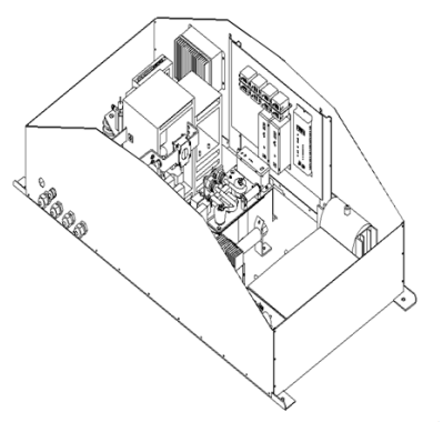
Vacuum circuit breaker DCU-800MNL (fig. 1) is a compact design inside which there is the main element (KG), which serves as a connector between the pantograph and the vehicle using the vacuum chamber (fig. 2). In turn, the auxiliary element (KP) is responsible for the inclusion of countercurrent during the shutdown whereas the second vehicle protection against short circuits is the element (ZF or ZPO). The source of countercurrent is the reactor (LK) and commutation capacitor (CK).The contact ssensor current (PIK) is responsible for the detection of short-circuit current. The energy needed to obtain high-speed traffic element (KG) is charged from the capacitors. The microprocessor control system, which uses fiber optics for the signal transmission, ensures the immunity of the electronic controls for distortion of the electromagnetic field.
The circuit breaker is equipped with a Harting connector, which acts as the main line system, via which communication between the switch and the vehicle takes place (the main driver of the drive system). Depending on your needs, we distinguish circuit breakers rated for control voltage 24 VDC, 110 VDC and special design 24/110 VDC.

Switch block diagram DCU-800M The applied microprocessor control system is equipped with a real-time clock and allows you, when you turn on the circuit breaker in the boarding pass CAN of the vehicle, to control the work validation of the circuit breaker on driver’s desk ETU and, in emergency situations, to determine the reason for not switching on of the circuit breaker or reason for its failure. Circuit breakers type DCU-800MNL are currently used by Regional Transportation for which the vehicles type IMPULSE were provided by the Polish company Newag in Nowy Sącz.
DCU-800MNLD
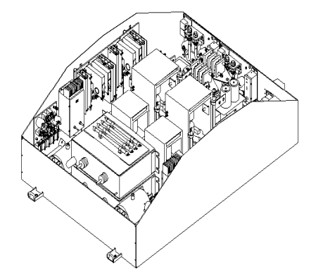
Vacuum circuit breaker type DCU-800MNLD is a special version of type DCU-800MNL. Inside the cover there are two independently acting switches to ensure high factor readiness of the vehicle to operate (fig. 3). FEA Woltan produced the double configuration circuit breaker in a steel cover with dimensions 1800x1179x532 for the purposes of the ETU single. Due to the limited space and the imposed dimension of the cover, the kind offered by FEA Woltan is the only one introduced to active service in Poland.
When designing a circuit breaker in the double structure, the main idea was to create a product that guarantees reliability. Because the vacuum circuit breakers are modular, so in order to fulfill the customers’ needs FEA Woltan expanded the functionality of the circuit breaker by designing a common output for both vacuum breakers.
This solution resulted in parallel connection of circuit breakers to the catenary and the vehicle. Each circuit breaker is connected to the catenary by means of a separate pantograph (fig. 4). Depending on the direction of movement of the vehicle the first or the second circuit breaker is switched on. The introduction of a new configuration of the power circuit breaker ETU required the analysis of the technical parameters and carrying out additional tests for checking the correct operation of the circuit breaker DCU-800MNLD depending on the different configurations: circuit breakers (included/excluded) and pantographs (abandoned/raised).

Technical parameters
The technical parameters of vacuum circuit breakers of direct current type DCU-800M are unreachable for classic solution circuit breakers DC. If we assume nominal short-circuit conditions:
• rated operational voltage Ue = 3000 V,
• short-circuit expected Isp = 50 kA,
• time constant of circuit t = 20 ms,
• initial current rate of rise si = 2,5 A/μs,
for the above parameters the total break time of short-circuit currents by using the vacuum circuit breaker DCU-800M is not longer than 2.2 ms. The dynamics of the drive system guaranteeing the achievement of such a short time to open the DC circuit should ensure the full protection not only for the vehicle against the effects of short circuits in the catenary or circuits of the vehicle, but it should also fully secure the second connected in parallel circuit breaker. In order to verify the assumption a study to verify the declared time to open the DC circuit and voltage on the auxiliary chamber was conducted.
Testing the opening times of circuit breaker DCU800MNLD for a different configuration of power and (included/excluded) circuit breakers and the surge and voltage value on the auxiliary chamber.
Research of testing the opening times for a single circuit breaker and circuit breakers working in parallel was made in the Short-circuit Laboratory of Electrical Apparatus of the Technical University of Lodz. Measurements have confirmed a constant value of the opening time of the DC circuit regardless of the type of work.
A more important parameter of the work of the circuit breaker is the value of the voltage and its variability in the auxiliary chamber (in the countercurrent circuit) of the circuit breakers working parallel to the catenary. If we give the voltage 3 kV on the power terminals circuit breaker 1 and 1′ and then close the main chambers (KG), such circuit terms of the catenary together with closing any of the auxiliary chambers (KP) will be in a short time of around 200 ms short circuit.

Voltage measurements on vacuum chambers (KP) were performed according to the measuring system shown in (fig. 5).
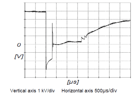
Measurements were taken in two modes during the process of a single-switch off and when the two circuit breakers were working in a parallel way. In the first place the voltage at the auxiliary chamber, voltage at the commutation capacitor and the supply voltage for the circuit breaker 1′ (individual work) were measured. Voltage oscillogram is shown in (fig. 6). The measured values of voltages are given in table 1.
Table 1. Measured characteristic Voltage

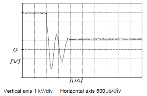
The second series of measurements were made by measuring the voltage on the auxiliary chamber of circuit breaker 1′ during the parallel operation (circuit breaker 1 turned on). Voltage oscillogram is shown in (fig. 7). The measured values of voltages are given in table 2.
Table 2. Measured characteristic Voltage

Research shows that the voltage at the auxiliary chamber circuit breaker 1’ (fig. 6) varies depending on the process of shut-down. At the moment of opening of the contacts of the chamber (KG) voltage changes from the value of the 3950 V to the value of about -3000 V. After about 400 ms contacts of the auxiliary chamber close for 300 ms. Then, when you open the chamber the voltage between its contacts exponentially rises to the value of 3000 V. The difference of voltage before the closing of the chamber (KP) and it is reopening after the completion of the shut-down process equals 950 V.
In the second case, for the parallel operation of vacuum circuit breakers 1 and 1′ (fig. 7) the oscillating type of voltage in the auxiliary chamber (KP) was recorded, it lasted approximately 850 ms. This is the result of the flow of energy between the commutation capacitors of the circuit breaker 1 and 1′. The difference of voltage before the closing of the chamber (KP) and its reopening after the completion of the shut-down process equals 2850 V.
Oscillograms (fig. 6) (fig. 7) were recorded during the current less work of circuit breakers.
The confirmation of the correct work of the circuit breakers is a short-circuit test based on turning on both circuit breakers onto the compact power supply network. In the oscillogram (fig 8) voltage on the contacts of the auxiliary chamber circuit breaker 1′ was recorded. The measured values of voltages are given in table 3.
Table 3. Measured characteristic Voltage
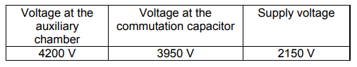

Contacts of the chamber (KP) remain closed for 400 ms, then the chamber is opened for 500 ms. From that moment the circuit breaker 1′ is opened. The further part of the course shows the effect of the closure of the auxiliary chamber circuit breaker 1 on the voltage waveform on the chamber (KP) of circuit breaker 1’. After the completion of the shut-down process the increase voltage on contacts chamber (KP) from the value of the 3950 V to 4200 V was registered. Voltage increase was caused by the flow of energy from a commutation capacitor circuit breaker 1 to the commutation capacitor circuit breaker 1′. During the test one observed the activation of both circuit breakers and signalling the exclusion of a short circuit.
Summary
During the parallel operation of two vacuum circuit breakers DC one found the interaction of one circuit breaker onto another. In the carried out, research circuit breaker 1′ switched off first, which led to, for a short circuit, breaker 1 switching off, too. These studies confirm the correct work of circuit breakers type DCU-800M in the case of detection of short circuits in the circuit. Parallel operation of two circuit breakers can be used when one wants to ensure the continuity of the drive system and auxiliary circuits of the ETU. It is ensured only when the vehicle is at a stop and one wants to change the steering cabin of the vehicle. If circuit breakers are working in parallel (redundantly) and one wants to switch off one of them, then, the high voltage circuit should be interrupted first by abandoning the pantograph and then sending a signal of switching off the circuit breaker. Otherwise, one will detect a short circuit and be turning off of both circuit breakers.
REFERENCES
[1] Bartosik M.,Wójcik F.,Lasota R.,Fast vacuum circuit breaker type of DCU-800 to shunting locomotives EM10, tts6 (2004), 36-37
[2] J. Magnusson, A. Bissal, G. Engdahl, J.A. Martinez-Velasco, “Design Aspects of a Medium Voltage Hybrid DC Breaker”, in 5th IEEE PES Innovative Smart Grid Technologies Europe (ISGT Europe), Istanbul, Turkey, 2014, pp. 1-6.
[3] A. Shukla, G.D. Demetriades, “A Survey on Hybrid CircuitBreaker Topologies”, IEEE Trans. Power Del., vol. 30, no. 2, 2015, pp. 627 – 641.
[4] Borkowski P., Błaszczyk H., The test protocol circuit breaker DCU-800MNLD, Łódź, 11.2017 r.
[5] Nowak Ł., Zaremba Ł., The test protocol with parallel operation circuit breakers used in the construction of DCU-800MNLD, Łódź, 06.2017 r.
[6] Zaremba Ł., Nowak Ł., Szymański S., Operation and Maintenance Manual ,,DC vacuum circuit breaker DCU-800M, DCU-800MNL, DCU-800MNLD’’, Łódź, 05.2017 r.
Authors: prof. dr hab. inż. Piotr Borkowski, Department of Electrical Apparatus of the Technical University of Lodz, ul. Stefanowskiego 18/22, 90-537 Łódź, E-mail: piotr.borkowski@p.lodz.pl;mgrinż. Łukasz Nowak, Department of Electrical Apparatus of the Technical University of Lodz, ul. Stefanowskiego 18/22, 90-537 Łódź, E-mail: Factory of Electrical Apparatus,,WOLTAN’’, ul. Gdańska 138, 90-536 Łódź, E-mail: Stanisław.szymanski@woltan.com.pl;
Source & Publisher Item Identifier: PRZEGLĄD ELEKTROTECHNICZNY, ISSN 0033-2097, R. 94 NR 8/2018. doi:10.15199/48.2018.08.32
