Published by Marcin JANUSZEWSKI, Ryszard KOWALIK, Karol KUREK, Emil BARTOSIEWICZ, Adam SMOLARCZYK, Désiré D. RASOLOMAMPIONONA, Warsaw University of Technology, Electrical Power Engineering Institute
Abstract. This article describes the comparison of test results of distance protection functions (ANSI 21) implemented in protective relays of various manufacturers dedicated to HV and EHV lines protection. A special emphasis has been placed on determining the operating times of distance protection functions based on quadrilateral and circular characteristics.The research was conducted using classical methods based on the use of software provided by the manufacturer of microprocessor-based tester and the use of simulation programs.
Streszczenie. W artykule opisano porównanie wyników badań funkcji zabezpieczeń odległościowych (ANSI 21) zaimplementowanych w przekaźnikach zabezpieczeniowych różnych producentów przeznaczonych do ochrony linii WN i NN. Szczególny nacisk położono na wyznaczenie czasów zadziałania funkcji zabezpieczeń odległościowych na podstawie charakterystyk czworokątnych i kołowych. Badania prowadzono metodami klasycznymi w oparciu o oprogramowanie dostarczone przez producenta testera mikroprocesorowego oraz programy symulacyjne. Badania funkcji zabezpieczeń odległościowych (ANSI 21) zaimplementowanych w przekaźnikach zabezpieczeniowych różnych producentów przeznaczonych do ochrony linii WN i NN
Keywords: HV line protection, EHV line protection, quadrilateral characteristic, mhO characteristic, circular characteristic, distance protection.
Słowa kluczowe: Zabezpieczenie linii WN, Zabezpieczenie linii NN, charakterystyka czworoboczna, charakterystyka MHO, charakterystyka kołowa, zabezpieczenie odległościowe.
Introduction
Detecting and elimination of short circuits occurring in power system is the main task of power protection systems, crucial for the stability and reliability of the power system. The time for short-circuit elimination consists of protection trip times, the delays introduced by the auxiliary relays and the time required for the disconnection of the circuit breaker contacts and the breakdown of the short-circuit current. HV/EHV lines are protected from the effects of short circuits by using i.e. two distance protection devices with different operating principles (mandatory solution for EHV lines protection in Polish National Power System). The main advantages of distance protection are the operation speed, i.e. the short time calculated from the moment when the short-circuit occurs until the instant at which a signal is received at the CB coil, and the selectivity – the ability to precisely isolate the impaired network fragment.
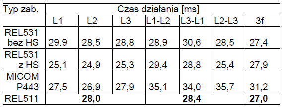
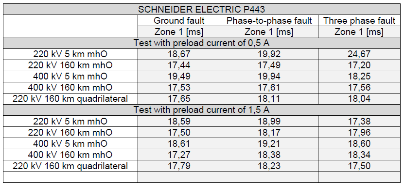
The Polish transmission system operator uses distance functions with only polygonal characteristics for both types of faults (phase-to-phase and earth fault). This is due to the fact that for earth and phase-to-phase faults, resistance ranges can be easily formed, which enables detuning from: transition impedance (resistance) and load. However, the obtained operating times of polygonal characteristics, especially for older constructions (results from 2006 are shown in Tab. 1), clearly show that the devices with mhO characteristics used at that time allow for operating times significantly below 20 ms (e.g. P443 relay), which is their great advantage.
In addition to older solutions, there were limitations in the distance function settings, such that after selecting the polygonal characteristic for phase-to-phase faults, the same characteristic in terms of shape was also used for earth faults. It was the same with the mho characteristics. If two protections are used to protect the line and they have the option of selecting the operating characteristics, one may attempt to set the polygonal characteristics in one of them and mhO in the other. The differences in the operating times between the polygonal and mhO characteristics are particularly visible for phase-to-phase faults and amounted to several ms, therefore, if it is possible to set the mhO characteristics in one of the protections, it should be done. Phase-to-phase faults are more dangerous for the system because they can lead to a loss of stability faster and in such situations we mainly care about the fast operation of the relay. Setting the polygonal characteristic in the second relay enables easy adjustment to the transition impedance and safe elimination of less dangerous earth faults.
The quoted results of tests of older versions of protection devices and the reflections resulting from them resulted in an attempt to answer the questions whether also in the case of modern protection devices and their distance functions: – there are the mentioned differences in the times of operation of the distance function with polygonal and mho characteristics, it is a good idea to set the mhO characteristics for phase-to-phase faults and polygonal faults for earth faults, and whether the choice of characteristics is possible in all devices of this type. Additionally, while performing a set of tests, an attempt was made to indicate which relays offer better operating times and when and for which conditions it is worth using a different way of setting the distance function.
Tab. 1. Average operating times for the relays tested in IEN until 2006 (polygonal characteristics)
Modeling and testing of distance relays is widely reported in the literature. Quite a big number of models has been developed by manufacturers and used by utility engineers to investigate new designs and test existing relays. Marttila presented a study [1], in which mhO elements of distance relays were modeled for studying the effect of the type of polarization on the directionality of the relays and for verifying the performance of the relays during specific operating conditions. Kennedy et al. [2] presented other models which were used for developing an improved method for testing voltage polarized mhO relays [1][2] and yet another study [8] developed a state-space model of an electromechanical distance relay for studying the transient behavior of the relay.
In order to ensure directional integrity for close-up faults, distance relays measure phase to ground or phase to phase impedance by including into the polarizing voltage a signal derived from another phase or phases during the fault (cross polarization), or from the pre-fault voltage (memory polarization), or some combination of both. This method is explained in detailed in [1][7]. The effect of these additional polarizing signals when used in a typical phase comparator solution is to expand the trip characteristic into the third quadrant of the impedance plane for forward faults and to close it down to a small circle in the first quadrant (not including the origin) for reverse faults.
In the sixties Phaff and von Buzay [4] in Switzerland and Wedepohl [5] in England published papers on the expanding nature of the cross and quadrature polarized mhO distance relays. In the seventies manufacturers recommended to conduct field testing at the relay set point and stated that it was sufficient and testing for the expanded polar characteristic was generally not encouraged. Anyway a few other protection teams have demonstrated that testing at the relay set point does not prove that all the relay components are functioning correctly. There are two other complementary methods: the first method [6] treats the relay characteristic as an unknown, calculates and applies a series of test voltages and currents until the characteristic is found to a desired accuracy. The second method [7] treats the relay characteristic as a known and determines a set of voltages and currents to match the characteristic. In the middle of eighties Peng et al. has presented a study [8], where a state-space model of an electromechanical distance relay was developed for studying the transient behavior of the relay.
Another aspect on which an attention should be paid is the encroachment issue. For forward faults the reactive reach is maintained at the original set point but the resistive reach increases with increase in source impedance. Distance elements of protective relays must be selected and configured in such a way that they will provide sufficient resistive reach to ensure correct operation when a fault is inside of the designed zone of protection [9][10]. The resistance of the arc has to be taken into consideration. It is affected my many factors, such as the distance between the phases and the extension of the arc by wind. To avoid an encroachment into the outer tripping zone usually the third zone – and an undesirable tripping, there are several countermeasures state of the art like characteristic shape shifting (e.g. forward offset of mhO characteristic) or adding restrictive areas in the R-X-impedance plane as a so called load blinder[11][12]. At the same time the characteristic should have a shape and settings that make it narrow enough so that the dynamically changing load impedance does not enter inside the characteristic. A careful choice of the amount of additional polarization is to be made when the protected line contains series compensation. According to Marttila [13] it cannot be assumed that the compensation will always be in circuit and the polarization setting is unlikely to suit both the fully series compensation configuration and the configuration without series compensation at all.
With the advent of numerical relays, the operation of which is based on calculation of impedance from the fundamental phasor voltage and current estimates, many new impedance characteristics can be implemented [14]. The shape and placement of operating zones in the impedance plane can be chosen with much greater freedom than in the past when the relay designer was limited to simple combinations of straight lines and circular arcs [15].
Certain limitations of the mhO circle can be overcome with the introduction of static and numerical relays. It is common to consider that quadrilateral characteristics are better to deal with ground faults on short lines in particular. A lot of authors consider that quadrilateral characteristic is most preferred when protecting short transmission lines as this provides substantial resistive coverage and arc compensation than the traditional circular characteristics [16].
Reducing the time of protection activation (pick-up time) is one of the possible ways to shorten the time needed to eliminate the short circuit. In order to check the possibility of pick-up time reduction, comparison tests of P443, REL670, 7SA522 and D60 relays equipped with two types of distance protection characteristics – quadrilateral and mhO were performed.
The comparison of relay operating times was aimed at answering one question: is there any advantage in changing the quadrilateral characteristics commonly used in distance protections of the Polish National Power System into mhO characteristics? Will this change in the case of one of the protections used can lead to any reduction of the protection operation time? The technical documentation of the relays [17]-[20] says that the principle of operation of mhO characteristics is based on the use of phase comparators, while the quadrilateral characteristics – on the use of amplitude comparators.
Description of the Analyzed Devices
In order to check the possibility of lowering the distance relay trip time, several devices of leading manufacturers were tested. It was necessary to equip the relays with the two types of previously discussed characteristics. The tests aimed to compare the operating times of distance functions based on phase comparators (mhO characteristics) and amplitude comparators (quadrilateral characteristics). Preliminary assumptions were to conduct tests under identical conditions for both characteristic types and each relay individually. This allowed comparing operating times and finding an answer, if could there be an advantage of using another type of characteristic for the given operating conditions. In addition, the tests were designed to determine the dependency between the type of fault, its location, and the length of the protected line.
The following protective devices were tested:
• Schneider Electric MiCOM P443, Firmware version: P443 6 570 D,
• Siemens 7SA522, Firmware version: V04.73.03,
• General Electric D60 Firmware version: D60 revision 6.0x (6.00),
• ABB REL670, Firmware Version: 1.5.0.57.
Testing algorithm of distance protections
Standard testing methods for distance relays, using the CMC microprocessor tester and for example Omicron’s Advanced Distance module, are perfect for conducting tests that are compatible with [21] or performing operational tests of under-impedance relays. In general, it does not matter whether the relay has active quadrilateral or mhO characteristics. The results are reproducible and can be used to determine the characteristics of the various proposals of solutions. However, by analyzing the resulting test waveforms generated by the Advanced Distance module, it must be stated that they do not reflect the actual currents and voltages that occur during short circuits. It follows that the resulting operating times are characteristic for the given conditions of operation. Of course, performing such tests is purposeful and allows determining the relay characteristics, but in specific cases may not reflect the full potential of the device.
Since distance functions or, in general, their operation algorithms take into account real-world phenomena, they should be tested using real-wave simulators and short-circuits in power systems [22][23]. It is also necessary to preserve the appropriate short-circuit time – so that the tested relay has the ability to determine its initial parameters. This type of test allows obtaining complete data on the possible behavior of the relay under the conditions it was designed by the manufacturer.
Bearing in mind the issues mentioned above, it was decided to check the relay operation times in several stages of analysis.
The CMC256plus tester and Omicron’s Advanced Distance module were used in the first stage of tests to verify the correct zone settings for 220 kV and 400 kV lines and two 5 km and 160 km lengths. Correct operation of the relays for the selected line voltage level, various line lengths, different operating characteristics and each type of fault has been confirmed. While performing this type of test, the operating times were not checked, and only the correctness of the range was determined.
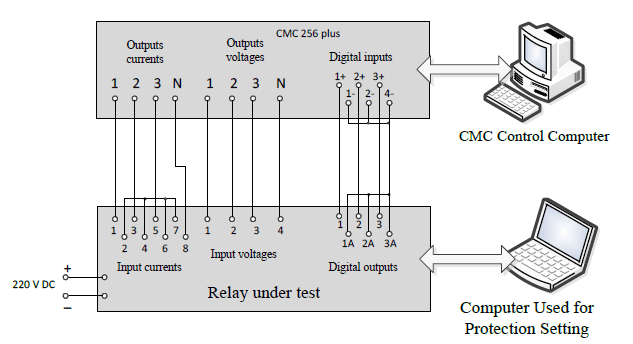
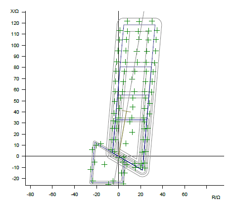
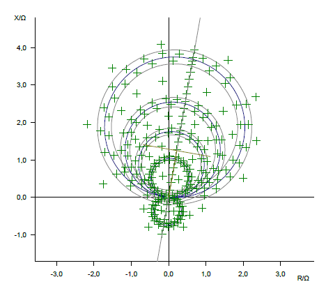
In the second stage of the tests the operating times of the ANSI 21 and 21N distance functions were checked. The CMC-156 tester and the Advanced Distance module were used for this purpose. Each test consisted in forcing the appropriate voltages and currents simulating the short-circuit currents corresponding to the test points described on the impedance plane. The tests included both mhO characteristics (Fig. 1, Fig. 2) and polygons (Fig. 3, Fig. 4). The tests were performed for the general circuit shown in Fig. 8. All types of faults were checked for all zones, taking into account the line length and the voltage level. It should be noted that each zone was set according to the range of the first zone, fixed for the given line length.
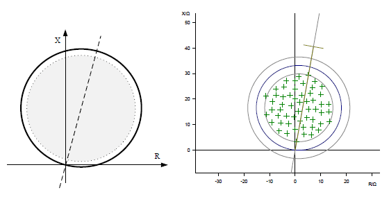

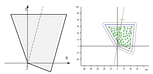
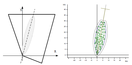
For each type of characteristics two sets of tests were performed. The first one covered the area of the full zone – except that the measurement points were shifted by 10% from the zone boundary (Fig. 1 and Fig. 3). In the second case, the test area was limited so that the measuring points were near the line short circuit angle (Fig. 2, Fig. 4). Thanks to such demarcation of the test areas, it was possible to see that, in the case of short circuits near the short circuit angle, the average elimination times are shorter than the elimination time for the full area. All tests using the Advanced Distance module were performed using a constant current set to 2In.
In the third stage of the tests, the PSCAD/EMTDC software was used in order to reproduce more accurately the conditions and phenomena occurring in power systems during short circuits. A simulation model consisting of two equivalent subsystems, connected by a 400 kV or 220 kV transmission line, was created. A simplified scheme of the system is shown in Figure 7. It allows simulating a short circuit at any point of the line and exporting to COMTRADE format waveforms of the simulated voltages and currents observed at the two ends of the line under test. The use of this type of simulation in opposition to the Advanced Distance test allows for better representation of phenomena occurring in a real power system. A series of simulations were prepared, covering two lengths of the test line (short line – 5 km and long line – 160 km, for two voltage levels) and all types of earth and phase faults. Short circuits are simulated at different distances from where the relay was installed. In addition, the simulations were carried out with the initial load at the level of 50% and 150% of rated load.

All types of tests in the third stage were carried out with the OMICRON CMC 256plus tester. Each of the tests consisted in simultaneously inducing corresponding voltages and currents, simulating short-circuit currents measured at the relay point R1 (Figure 5). This was achieved by using the AdvancedTransPlay module included in the Test Universe package. It allows importing a set of waveforms and currents from the COMTRADE format, assigning them to the corresponding test outputs, and then synchronizing them to the analog inputs of the relay – according to the measurement circuit shown in Figure 6.
Test Results Stage I – Confirmation of the Correctness of Zone Setting
While performing this type of test, the operating times were not checked, and only the correctness of the area range was determined. Obtaining results has confirmed the correctness of the settings made and allows moving to the next stage of the tests. Correct operation tested relays has been confirmed by the results.
Some sample results of P443 relay operation are shown in Fig. 7 and Fig. 8. Similar tests were performed for the remaining relays, for each line voltage level (220 kV and 400 kV), different line lengths (5 km and 160 km) and all types of short circuits. All types of tests were performed using Omicron’s Advanced Distance module and fixed current mode Iz = 2In.
Stage II – Classic Tests for the Full Zone Area and for Short-circuits around the Short-circuit angles
Short circuits occurring in the full area of the zone and short circuit near the line short circuit angle were simulated using Omicron’s Advanced Distance module (in constant current mode). According to previous information, the tests were carried out for 400 kV and 200 kV lines, the lengths of which are 5 km (short line) and 160 km (long line). Operating time were compared for two types of distance function characteristics : mhO and quadrilateral. In the case of using these outputs are also checked. This allowed determining the benefits of using high speed digital outputs.
Aggregated test results for the P443 relay are shown in tab. 2. They are the average results obtained for zone 1 and the other zones. The analysis of obtained results has shown that distance protection with mhO characteristics seems working better for the P443 relay. The difference is particularly noticeable in operating time for long lines, in case two-phase and three-phase short-circuits are simulated. The protection using a phase comparator works in these conditions even faster by about 5 6 milliseconds. For tests in the full coverage area, the P443 with mhO characteristics is much faster for short lines. For long lines, the switching times are shorter in case of distance function with quadrilateral characteristics. In the case the short-circuit is near the short-circuit angle, we can count on fault elimination times significantly below 20 ms for the P443 relay.
The tests for the P443 relay were carried out using two types of binary outputs. One of them is the Highbreak digital outputs, which significantly shortens the overall trip time by an average of 4 milliseconds. This time is constant independent of the test conditions. Results shown in tab. 2 refers to the times obtained using Highbreak high-speed outputs.
Similar results have been obtained for the relay 7SA522. The analysis of the obtained results makes come out to the conclusions that there is an advantage in the speed of mhO protection characteristics over the quadrilateral ones. The analysis of the obtained operating times in an area close to the line short-circuit angle leads to the conclusion that the difference is greater for two-phase and three-phase faults for a long line and the time differences range from about 2.5 to even 10 milliseconds.
Stage III – Simulation Tests
A simulation model consisting of two equivalent subsystems (Figure 7) connected by a transmission line of rated voltage of 400 kV or 220 kV was built in order to conduct a few simulation tests for the third stage of the analysis. This model allowed simulating a short circuit at any point of the line and exporting (to the COMTRADE format) the waveforms of the simulated voltages and currents observed at the two ends of the line under test. For the tests described, a set of currents and voltages coming from one end of line (R1) was used. If compared to the tests performed with the Advanced Distance module, the simulations conducted are characterized by a better reproduction of the phenomena occurring in the real power system, and allow the testing of operating times of fast distance protections with algorithms adapted to the transition phenomena occurring in power systems during short-circuits. Thanks to the classic Test Universe (Advance Distance) software and CMC tester, currents and voltages that consider only the values of the first harmonic, with alternating currents and voltages are induced. This can introduce some significant delays in distance protection performance that do not occur when testing these protections with near real-life waveforms.
Tab. 2. Summary of average P443 protection operating times, for tests of full characteristics and tests near the short-circuit angle

Tab. 3. Summary of average P443 protection trip times for simulation tests
Bearing this in mind, a series of simulations were prepared, covering two lengths of the analyzed line (a short line of 5 km and a long line of 160 km) and all types of earth and phase faults. The operating time of a given function was measured from the occurrence of a short-circuit to the occurrence of a logic signal indicating the pick-up of the distance function.
P443 relay simulation tests, the results of which are shown in tab. 3, did not show any significant difference in the time gained between the quadrilateral characteristics and mhO. The device operated at a similar speed, both for 0,5In and 1,5In. preload currents. It should be noted that the resulting operating times are very good and do not normally exceed 20 ms – no matter if the short circuits were single-phase or phase-to-phase.
The results of the simulation tests of the relay 7SA522 (not displayed here for the sake of room) allow to assert that the 7SA522 relay works well in conditions very close to real ones. It should be noted that for this test variant the difference in response time for both the quadrilateral characteristics and mhO disappears. The relay maintains short operating times for both 0,5In and 1,5In loads. Line to earth, phase-to-phase and three phase fault elimination times are similar.
In general, the results of relay simulation tests allow to assert that the relays get much shorter times in near real conditions. In addition, for phase-to-phase faults, a further reduction in response time is observed with an increase in the initial load current.
Conclusions
Any way to accelerate the operation of transmission line protection helps to increase the security of the power system. Results obtained during protective device analysis carried out in the laboratory of the Institute of Electrical Power Engineering, Warsaw University of Technology allow to state that the use of commonly known mhO characteristics can significantly influence the short-circuit elimination times and their use should be considered in the currently installed distance protection systems. It is important to define the goals that we face when designing protection systems and the conditions of their operation. Based on the tests carried out, it is possible to select the appropriate operating characteristics of the equipment to achieve the shortest possible short-circuit elimination times for the existing conditions while ensuring high reliability.
In addition, given that the 220 kV and 400 kV transmission lines are protected by, for example, two under-impedance protections, it is worth considering the setting in one of them a distance protection based on mhO zones dedicated to the rapid elimination of phase-to-phase faults, as this may result in significantly better short-circuit elimination times during this type of fault.
Faster operation of the protection automation can be particularly important for the elimination of phase-to-phase faults in power lines forwarding the energy from the power plant, where fast operation of protective systems may be required in case of contingency. In other cases (single-phase short-circuits or other short-circuits in transmission lines) the use of quadrilateral characteristics seems more appropriate because of the possibility of easier shaping of the resistance ranges of particular zones.
In addition, it should be noted that in modern distance protection rapid action in first zones is usually assisted by additional algorithms that consider the specific characteristics of short circuits that are not mapped by the basic functions of the microprocessor testers. Therefore, especially during the testing of distance protection operating times, in addition to classical tests, some tests that characterize actual short-circuits should be performed. Only such information gives a full picture of the capabilities of a given relay.
REFERENCES
[1] R. J. Marttila, “Directional Characteristics of Distance Relay Mho Elements- Parts I and II”, IEEE Transactions, Vol. PAS-100, No.1, January 1981, p96.
[2] Kennedy, W.O. et al., “Five years experience with a new method of testing cross and quadrature polarized relays: part I, results and obrservations”, IEEE Trans. On power delivery, Vol. 3, July 1988, pp 880-886.
[3] Kennedy, W.O. et al.,, “Five years experience with a new method of testing cross and quadrature polarized relays—Part II: Three case studies”, IEEE Trans. on Power Delivery, vol. 3, no. 3, pp. 887–893, July 1988.
[4] C.J.R. Phaff and K. von Buzay, “Circle Diagrams of Directional Impedance Relays.”, Brown Boveri Review vol. 49 pp 173-189, 1962.
[5] L.M. Wedepohl, “Polarized Mho Distance Relays – A New Approach to the Analysis of Practical Characteristics.” Proceedings of IEE vol. 112 No. 3 pp 525-535 March 1969.
[6] G.W. Swift, L.M. Wedepohl, A.W. de Groot, N-J Morphy, and J. Mohd-Jarjis, “An Automated Testing System for Distance Relays.”, IEEE Transactions on Power Apparatus and Systems Vol. PAS-96, pp. 1376-1383 July/August 1977.
[7] W.O. Kennedy, “Field Testing of Polarized Mho Distance Relays Under Unbalanced Fault Conditions.”, CEA Transactions of the Engineering and Operating Division vol. 20 part 4 Paper No. 81-SP-157, 1981.
[8] Z. Peng, M. S. Li, G. V. Wu, T. C. Cheng, and T. S. Ning, “A dynamic state space model of a MHO distance relay”, IEEE Trans. on Power Apparatus and Systems, vol. PAS-104, no. 12, pp. 3558–3564, 1985.
[9] A. P. Apostolov; D. Tholomier; S. H. Richards, “Distance protection and dynamic loading of transmission lines”, IEEE Power Engineering Society General Meeting, Year: 2004, Pages: 100 – 105 Vol.1.
[10] D. Tholomier; S. Richards; A. Apostolov, “Advanced distance protection applications for dynamic loading and out-of step condition”, 2007 iREP Symposium – Bulk Power System Dynamics and Control – VII. Revitalizing Operational Reliability, Year: 2007.
[11] S. H. Richards; D. A. Keeling; A. P. Apostolov, “The next challenge: distance protection designed for ease of application”, 2004 Eighth IEE International Conference on Developments in Power System Protection, Year: 2004, Volume: 2, Pages: 788 – 791 Vol.2
[12] J. Schindler; J. Jaeger, “Advanced load blinding of distance protection relays based on physical grid limitations”, 2016 IEEE Power and Energy Society General Meeting (PESGM), Year: 2016
[13] R.J. Marttila, “Performance of distance relay mho elements on MOV protected series compensated lines”, paper no. 91 SM 362-4 PWRD, PES Summer meeting, San Diego, July 1991.
[14] McLaren, P.G., Swift, G.S., Neufeld, A., Dirks, E.N., Zhang, Z., Haywood, R., “Open systems relaying.”, Paper No. 93 SM 376-4-PWRD, IEEE PES Summer Meeting, Vancouver, July 1993.
[15] Mathews, P., Nellist, B.D., ”Generalised Circle Diagrams and their Application to Protective Gear”, AIEE Transactions] Power Apparatus and Systems, No. 2, February 1964, p. 165.
[16] J. Holbach, V. Vadlamani, and Y. Lu, “Issues and Solutions in Setting a Quadrilateral Distance Characteristic”, proceedings of the 61st Annual Conference for Protective Relay Engineers, College Station, TX, April 2008.
[17] MiCOM P443 and P446 Fast Multifunction Distance Protection P44y/EN M/C32+C42 CONTAINS Software Update: 57 K (P44y/EN AD/C42) Technical Manual: 55 K (P44y/EN M/C32) Software Version 55/57 Hardware Suffix K – Technical Manual http://www.schneider-electric.com.
[18] D60 Line Distance Protection System UR Series Instruction Manual D60 Revision: 7.1x.
[19] Line distance protection REL670 Technical reference manual.
[20] SIPROTEC 4 Distance Protection 7SA522 V4.74 and higher Manual (http://w3.siemens.com/smartgrid/global/en/products-systems-solutions/protection/distance-protection/pages/7sa522.aspx ) .
[21] PN-EN 60255—121:2014-10 – Przekaźniki pomiarowe i urządzenia zabezpieczeniowe — Część 121: Wymagania funkcjonalne dotyczące zabezpieczeń odległościowych (Polish Standard PN-EN 60255—121:2014-10 Measurement relays and protection devices – Part II – Functional requirements for distance protection)
[22] A. Smolarczyk, R. Kowalik, E. Bartosiewicz, “Closed-loop testing method for protective relays with use of MATLAB/Simulink software”, The IET 12th International Conference on Developments in Power System Protection (DPSP) 2014, 31 March – 3 April 2014, Copenhagen, Denmark, ISSN ISBN: 978-1-84919-813-4, pp. 1-6, The Institution of Engineering and Technology (IET).
[23] A. Smolarczyk, R. Kowalik, E. Bartosiewicz, “A Simple Real-Time Simulator for Protection Devices Testing”, IEEE International Energy Conference (ENERGYCON), pp. 793-799, Dubrovnik, Croatia, MAY 13-16, 2014.
Authors: dr inż. Marcin Januszewski, Politechnika Warszawska, Instytut Elektroenergetyki, ul. Koszykowa 75, 00-662 Warszawa, E-mail: Marcin.Januszewski@ien.pw.edu.pl; mgr inż. Karol Kurek, Politechnika Warszawska, Instytut Elektroenergetyki, ul. Koszykowa 75, 00-662 Warszawa, E-mail: Karol.Kurek@ien.pw.edu.pl; dr hab. inż. Ryszard Kowalik, Politechnika Warszawska, Instytut Elektroenergetyki, ul. Koszykowa 75, 00-662 Warszawa, E-mail: Ryszard.Kowalik@ien.pw.edu.pl; Emil.Bartosiewicz@pse.pl, Polskie Sieci Elektroenergetyczne S.A. ul. Warszawska 165 05-520 Konstancin-Jeziorna; dr hab. Inż. Adam Smolarczyk, Politechnika Warszawska, Instytut Elektroenergetyki, ul. Koszykowa 75, 00-662 Warszawa, E-mail: Adam.Smolarczyk@ien.pw.edu.pl; prof. dr hab. Inż. Desire Rasolomampionona, Politechnika Warszawska, Instytut Elektroenergetyki, ul. Koszykowa 75, 00-662 Warszawa, E-mail: Desire.Rasolomampionona@ien.pw.edu.pl;
Source & Publisher Item Identifier: PRZEGLĄD ELEKTROTECHNICZNY, ISSN 0033-2097, R. 96 NR 11/2020. doi:10.15199/48.2020.11.43
