Published by H. X. Araujo1 , M. D. B. Melo1, I. R. S. Casella2 and C. E. Capovilla2,
Universidade Federal do Tocantins (UFT) (1), Universidade Federal do ABC (UFABC)(2),
Abstract. In this work, a low cost EMC – Electromagnetic Compatibility pre-compliance board, based on the conducted emission technique, is proposed as an option to analyze electronic devices used in telecommunications and smart grid network enviroments. In general, as the IC is the major responsible of unintentional emissions and coupling, some specific pre-compliance setup tests are employed to analyze these detrimental effects to the system as a whole. Therefore, an EMC Pre-Compliance Board was designed and built to operate from 150 KHz to 30 MHz. Simulated and experimental results are compared to validate the test setup.
Streszczenie. W pracy przedstawiono prosty układ umożliwiający testowanie i poprawę elektrokompatybilności urządzeń telekomunikacyjnych I wyposażenia sieci smart grid. Układ pracuje w zakresie częstotliwości 150 kHz – 30 MHz. Prosty układ dopasowujący EMC do urządzęń telekomunikacyjnych I sieci smart grid.
Keywords: EMC. EMI, conducted emission, telecommunications systems, smart grid.
Słowa kluczowe: elektrokompatybilność, sieci smart grid.
Introduction
Due to the increase of the microelectronic and embedded electronic systems, in the last years, every electronic device must be submitted to rigorous EMC test, and their entries in the market are directly related to it responses on these test. However, only in the late 70s that the problems related to EMC – Electromagnetic Compatibility became of public knowledge, in general, due to the problems presented by TVs, communication devices, audio and video displays, among many other applications [1]. Some approaches were designed to support the precompliance tests (EMC/EMI/EMS) setups, which are not designed to replace the well-known compliance equipments (anechoic chamber, stirring chamber, blue test chamber, etc) but, it gives a previously information about the device behavior [2]. All of them have consolidated standards and regulations.
On the other hand, the Smart Grid technology has become a subject of study [3], due the necessity of power quality and energy efficiency. However, the smartness of the grids is provided by electronics, which are in general the major responsible of unintentional emissions. Basically, as far as the smart grid control is developed with microelectronic components, the conducted emission levels from a household appliance should be carefully analysed, in order to guarantee the correct operation of the network. Moreover, the grid behavior must also be certified in order to ensure the correct operation of the devices connected to it in terms of electromagnetic compatibility.
In this work, the conducted emission levels from the household appliance are observed in order to ensure the correct operation of the devices connected to grid in terms of EMC. The obtained results were compared to the regulatory standard and it can be observed that most of the devices are out of it, thus compromising the performance of the grid as a whole. The test setup, was performed in accordance to CISPR and FCC – Federal Communications Commission, agency in charge of standardization of radio communications and cable in the U.S. The preliminary results were compared to CISPR 14-1[4] and CISPR 22 [5], depending on the class of the household appliance DUT.
EMC Conducted Method
The electrical power grids were developed using relatively few AC plants (50 or 60 Hz with very high-power), AC or DC interconnected, with many substations to attend residential or low-power industrial demands, as can be seen in Fig. 1. The Smart Grids (SG) are an evolution of the electrical power grids and are based on a more efficient employment of the generation, transmission, and distribution infrastructure. Its use is mandatory in order to manage the relationship between demand and power supply to avoid contingencies in the electrical system [6].
In this way, it is necessary to develop a whole telecommunications framework for a successful smart grid implementation. Inherently, its characteristic needs a strong interaction, composed by communication networks, realtime monitoring, and data management [7]. So, nowadays its integration is transforming the whole electrical energy scenario.
Therefore, the conducted emission levels from the household appliance are observed in order to ensure the correct operation of the devices connected to grid in terms of EMC. The electromagnetic interference – EMI is the process in which electromagnetic energy is transmitted from one electronic device to another via radiated or conducted emission or both. On the other hand, the electromagnetic susceptibility – EMS deals with devices sensitive to interference from other devices. Thus, the EMC tests usually comprise both EMI and EMS measurement of the same electronic device. In Fig. 1 is shown the coverage of the electromagnetic compatibility. Therefore, several EMC tests platforms were designed to evaluate the performance of electronic circuits and devices aimed at preventing problems related to interference or immunity within an electromagnetic environment. Among the most common and robust EMC platform, is the Anechoic Chamber [8], which for several years has been the main method of evaluating the electromagnetic behavior of antennas, electronic devices, vehicles and even airplanes. However, the high value required for their construction and maintenance, and the complexity of its operating system, makes infeasible its acquisition for the analysis of small electronic devices. Therefore, other methods less complex and costly show good results related to the interference and immunity analysis known as pre-compliance test.
Different approaches assist the pre-compliance test, which are governed by their own standards and rules. These setups include the TEM/GTEM cells, magnetic loop, magnetic probe, Workbench Faraday Cage, OATS – Open Area Test Site, 1/150 Ω conducted, LISN – Line Impedance Stabilization Network, among others.
The pre-compliance setup tests, at the level of electronic systems are defined by the standards CISPR 25/2002 (special international committee on radio interference) for spurious emissions, and the ISO-11452 for interference susceptibility measurements. Thus, two major standards have been defined, with a first one for radiated and conducted emission and the second one for immunity RF test.
By definition, the conducted interference is that in which occurs undesirable transfer of electromagnetic energy along a conductor through disturbances between the phase line and the ground power supply, and is governed by the standard IEC 61967-4. There are several tools and methodologies to perform conducted tests, and the frequency range normally used is 150 KHz – 30 MHz, except in military applications that eventually require the extension band.
The most common method used for this type of analysis is the LISN, also known by AMN – Artificial Mains Network, which works through the AC power supply of the device to be analyzed. In spite of the minimum frequency of the conducted emission tests is normally around 150 KHz, by the power switching held by the LISN is possible to achieve a minimum frequencies around 9 kHz. The advantages of using the LISN in conducted tests are mainly related to the fact that it provides electromagnetic insulation against the external environment and characterize the impedance of the DUT – device under test. However, its cost may be a limiting factor.
Other method widely used in performing conducted interferences measurements is the 1/150 Ω, where is possible to measure the noise current in each driven pin of the DUT. The basic model consists of the presence of a low value resistance in series with the output pin of the DUT. Therefore, it is possible to measure the voltage across the known resistor and then determine the noise current. Based on the fact that most IC emission problems arise through the noise that is carried out by the pins of the IC, this method presents itself as a good indicator. However, for each DUT and application the equivalent circuit must be adapted and adjusted.
Conducted Compliance Board
To evaluate the conducted emission provided by a laptop, an electromagnetic compatibility pre-compliance board using resistors, capacitors and inductors was designed and built. The schematic of the designed circuit is shown in Fig. 2. The series inductance avoids that the noise coming from the device under test becomes into the grid, being directed to the 1KΩ resistor on which the measurement is made using the spectrum analyzer. Any present noises on the line are misappropriated by the 1 μF capacitor placed in parallel with the network, thereby not not affecting the measurement.

To perform the simulations, the Multisim Software was employed. The board was designed to operate at 127 V and 60 Hz, the classical Brazilian standard. To obtain the impedance variation of the circuit as a function of the frequency, the AC analyses and the equivalent impedance were needed. In Fig. 3, is shown the EPCB unconnected and connected to a DUT and its impedance variation as a function of the frequency which tends to 50 Ω.

The test setup, as shown in Fig. 4, was performed in accordance to CISPR and FCC – Federal Communications Commission, agency in charge of standardization of radio communications and cable in the U.S. The test equipment used was a BK Precision Series 2650A spectrum analyzer, a certified FCC class B laptop, which served as the DUT and the EPCB. In Fig. 5, is shown the conducted emission scan of the fully configured, certified, class B laptop. To compare the response provided by the EPCB, a measurement with a commercial LISN was also done. Both results are compared to the CISPR and FCC standards. From the obtained results, is possible to observe the good agreement of this low cost pre-compliance test. As the laptop is certified, it was expected that the radiated emission levels must satisfied the standards. However, there are resonances around 30 MHz, which can be caused by disturbances, provided by battery charger, connections between the motherboard and peripherals devices or even due to the heating. Meanwhile, is important to emphasize that these resonances levels are minimal, and could also be inserted by the test platform.

Results
All the measurements was performed using the precompliance board shown in Fig. 1. The electronic devices are plugged in the compliance board, which is plugged at the electric power grid.
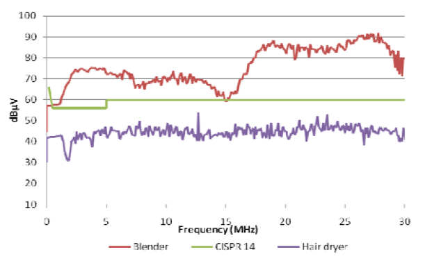
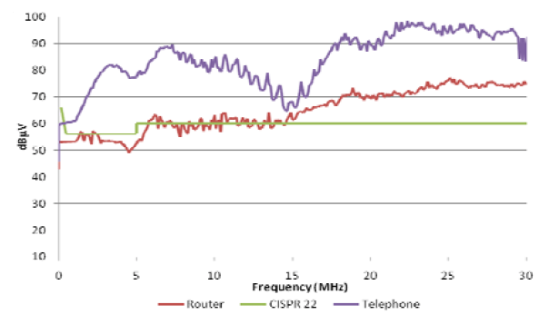
The obtained results for the electric heater, vacuum cleaner, blu-ray, sattelite TV decoder, blender and hairdryer were compared to the CISPR 14-1 standard, Figs 4 and 5, which refers to the conducted emissions allowed level, for household appliance devices. In the other hand, the router, wireless telephone, LED and tube TV, personal laptop and the printer were compared to the CISPR 22 standard, Figs 6, 7 and 8. Basically, as far as the smart grid control is developed with microelectronic components, the conducted emission levels from the household appliance should be carefully observed, in order to guarantee the correct operation of the network.
It can be easily observed from the obtained results, most of the analyzed appliances are out of the standards. Therefore, without any solution to prevent the undesirable emissions, the grid performance will certainly be compromised.


Conclusions
The voltage and current in distribution lines are often corrupted by transient, distortions and other disorders, that come from natural sources such as lightning and also by the operation of electrical and electronic devices. These interferences are conducted over long distances and then coupled to other equipments connected to the grid.
Therefore, in this work, an EMC Pre-Compliance Board was designed and built to operate from 150 KHz to 30 MHz. It was shown the development of the proposed device since the design, simulations and experimental measurements. Besides that, the conducted emission levels from some household appliance are observed in order to ensure the correct operation of the devices connected to grid in terms of electromagnetic compatibility.
The obtained results were compared to the regulatory standard and it can be observed that most of the devices are out of it, thus compromising the performance of the grid as a whole.
Acknoledgement The authors would like to thank Rogers Corporation and UFT – Universidade Federal do Tocantins – Novos Pesquisadores Program for the partial financial support.
REFERENCES
[1] A. Gunnar, K. Dursun, B. G. Hauge and B. Bremdal, Establishing Sustainable and Reliable Smart Grids, Applied Measurements for Power Systems (AMPS), 2013 IEEE International Workshop on., Aachen, Germany, 2013.
[2] Montrose, M. I. e E. M. Nakauchi, Testing for EMC Compliance, New York, 2004.
[3] F. R. L. Silva, L. R. Ribeiro, L. P. Dias, W. J. Santos, C. E. Capovilla, and H. X. Araujo, The Design and Implementation of an EMC Pre-Compliance Board, Progress In Electromagnetics Research Symposium Proceedings, Stockholm, Sweden, 2013.
[4] CISPR14-1 ed 5.1, Electromagnetic Compatibility – Requirements for household appliances, electric tools and similar apparatus – Part 1: Emission. International Electrotechnical Commission, 2009.
[5] CISPR22 ed 6.0, Information technology equipment – Radio disturbance characteristics – Limits and methods of measurement. International Electrotechnical Commission, 2008.
[6] V. C. Gungor, D. Sahin, T. Kocak, S. Ergut, C. Buccella, C. Cecati, and G. P. Hancke “A Survey on Smart Grid Potential Applications and Communication Requirements” IEEE Transactions on Industrial Informatics, vol. 9, n. 1, Feb. 2013.
[7] Y. Yan, Y. Qian, H. Sharif, and D. Tipper, “A survey on smart grid communication infrastructures: Motivations, requirements and challenges,” IEEE Commun. Surveys & Tutorials, vol. PP, no. 99, pp. 1–16.
[8] Z. X. Ji Chen and Z. Chen, “Low Frequency Modeling for Electromagnetic Analysis of a Arbitrary Anechoic Chambers”, IEEE International Symposium on Electromagnetic Compatibility, 2016.
Authors: Prof. H. X. Araujo, Universidade Federal Tocantins, Av: NS 15 ALC NO 14, 109 Norte – 77001-090, Palmas – TO, Brazil email: hxaraujo@uft.edu.br
Prof. M.D. B. Melo, Universidade Federal Tocantins, Av: NS 15 ALC NO 14, 109 Norte – 77001-090, Palmas – TO, Brazil email: maxwellmelo@uft.edu.br
Prof. I. R. S. Casella, Universidade Federal do ABC, Rua Santa Adélia, 166 – 09.210-170, Santo André -SP, Brazil email: carlos.capovilla@ufabc.edu.br
Prof. C. E. Capovilla, Universidade Federal do ABC, Rua Santa Adélia, 166 – 09.210-170, Santo André -SP, Brazil email: ivan.casella@ufabc.edu.br
Source & Publisher Item Identifier: PRZEGLĄD ELEKTROTECHNICZNY, ISSN 0033-2097, R. 93 NR 3/2017. doi:10.15199/48.2017.03.62
