Published by Wojciech SZOKA, Szymon BANASZAK, Konstanty M. GAWRYLCZYK
Zachodniopomorski Uniwersytet Technologiczny w Szczecinie, Katedra Elektrotechnologii i Diagnostyki, Poland
Abstract. Transformers are the main element of the power system. Their reliable operation affects the efficiency of energy supply. Each transformer should be subjected to periodic diagnostic tests. Frequency response analysis (FRA) is a non-destructive diagnostic method that detects deformations in windings. The paper presents research on the influence of the measuring setup on the efficiency of detecting various windings deformations in the transformer, which showed that the capacitive interwinding test setup is more sensitive than standard end-to-end test setup.
Streszczenie. Głównym elementem systemu elektroenergetycznego są transformatory. Ich niezawodna praca wpływa na jakość dostaw energii. Każdy transformator powinien być poddawany okresowym badaniom diagnostycznym. Analiza odpowiedzi częstotliwościowej (FRA) jest bezinwazyjną metodą do wykrywania odkształceń uzwojeń. W pracy przedstawiono badania wpływu układu pomiarowego na efektywność wykrywania różnych deformacji uzwojeń w transformatorze. Badania przeprowadzone w układzie międzyuzwojeniowym pojemnościowym wykazują skuteczność wykrywania deformacji lepszą niż w standardowym układzie pomiędzy końcami uzwojenia. (Zalety konfiguracji międzyuzwojeniowej pojemnościowej w diagnostyce uzwojeń transformatorów metodą FRA).
Keywords: Transformer, Frequency Response Analysis, FRA, windings.
Słowa kluczowe: Transformator, analiza odpowiedzi częstotliwościowej, FRA, uzwojenia.
Introduction
The windings of the power transformers are exposed to dynamic forces resulting from external short-circuits or overvoltages, which can lead to radial or axial deformations, and result in short-circuits between the turns. Periodic diagnostic tests can detect a defect or damage in the active part early enough to be able to schedule a replacement or repair of the unit before failure occurs [1].
One of transformers diagnostic methods is frequency response analysis (FRA). This method compares the low voltage sinusoidal signal of the variable frequency supplied at one end of the winding and recorded at the other end of the winding or the opposite voltage side. Comparison of wide frequency range signals allows detecting even the smallest changes in the electrical parameters of the active part of the transformer [2].
It is important that assessment of the technical condition of the transformer was reliable and gave a clear interpretation of the results. The paper presents comparison of four test setups efficiency in detection of various deformations in winding.
Measurements setups
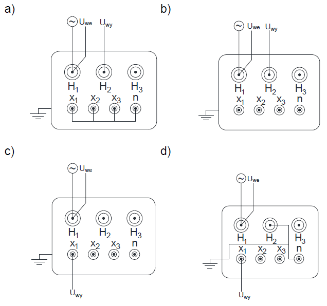
The FRA method uses four basic measuring configurations proposed by standard IEC 60076-18 [3, 4], which are end-to-end open, end-to-end shorted, capacitive interwinding and inductive interwinding. The most common measurements setup is end-to-end open configuration (Fig. 1a). The end-to-end open setup is performed on single phase winding with signal applied to one end and the response measured on the other side, with secondary winding left open [5]. The second test setup – end-to-end shorted (Fig. 1b) – removes the influence of magnetic circuit. This configuration can be used to investigate windings when there is a suspicion of damage in the core or to eliminate the uncertainty associated with the residual magnetization of the core. The end-to-end shorted measurement is performed almost the same as in open setup but in these configuration secondary windings are shorted. Practical experiences show that this test is not able to detect any additional cases of faults that are already detected by end-to-end open setup, so it can be omitted.
The capacitive inter-winding configuration (Fig. 1c) is based on applying the signal to one end of the HV winding and measurement taken on the end of LV winding of the same phase, with other ends of windings left open. Its results show the effect of construction of each winding and their mutual influence. All faults in the active part are related to capacitance changes, that are easily detected in this test setup.
The fourth measurement configuration is inductive interwinding test (Fig. 1d), which is similar to the capacitive interwinding test with the difference that the ends of the tested windings are shorted and grounded. This setup shows inductive correlation between windings, however in case of many deformations windings inductances are not changed and the values changes of local mutual inductances are too small to show detectable differences.
Tests with controlled deformations introduced into windings
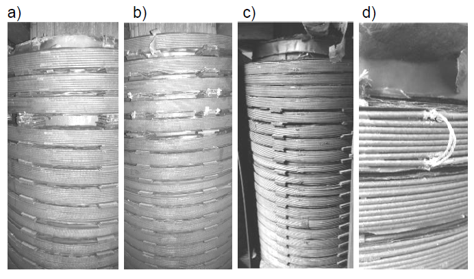
Measurement setups were compared on the basis of research carried out on a real transformer 15/0.4 kV, 800 kVA, in which controlled deformations were introduced into the winding. The first deformation (Fig. 2a) was axial shift of the whole discs by 6 mm and 12 mm starting from the first coil and ending on the fifth. The gap was increased always only between one pair of discs. The second deformation (Fig. 2b) was similar to the previous one, however the gap between discs was introduced in the same way for several discs at the same time. In other words winding was expanded by 6 mm, from first to fourth disc. The third deformation (Fig. 2c) was based on removing the original spacers between discs and lowering them one after another starting from the top to the fifth. The fourth deformation (Fig. 2d) simulated short-circuits between turns. At first there were shorted two adjacent turns in the first coil, then the whole disc was shorted, and finally two adjacent discs.
To eliminate, as much as possible, the unintended deformations caused by introduction of faults into winding, after each deformation and series of tests, the windings were restored to their original state to make a new reference measurement. The comparison of reference measurements recorded between subsequent deformations showed only slight differences.
Comparison of test setups efficiency
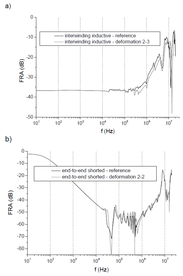
The analysis of results in all four tests showed, that only two of them give useful information on the condition of the winding. The first of them is end-to-end open (E2E), recommended as the standard and the only setup by IEC standard [3, 4]. The second is capacitive interwinding (IntCap), that clearly shows changes done in the winding geometry, usually differently and in wider frequency ranges than end-to-end open. Fig. 3 presents results of two test configuration that do not give significant changes in FRA curves after introducing deformations: end-to-end shorted and interwinding inductive. In the rest of the paper these two will not be discussed anymore. The end-to-end shorted test setup has removed low frequency range, while the rest of frequency spectrum is similar to end-to-end open, while inductive interwinding shows changes much smaller than capacitive test.
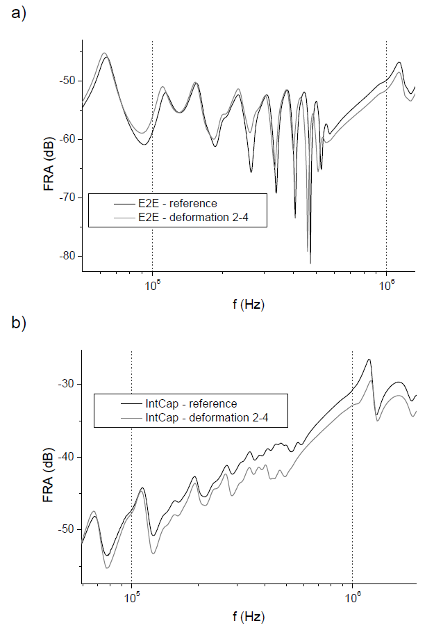
The following graphs present effect of four deformations introduced into windings on FRA curve shape. Only zoomed ranges are given on graphs and chosen results for each deformation to keep presentation clear. The first pair of graphs (Fig. 4) shows the influence of the first deformation (presented on Fig. 2a).
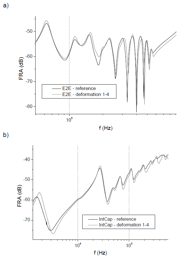
It can be seen that both test setups give clear results, the influence of shifted discs is obvious and appears in frequency range expected for such size of tested transformer. However, the character of changes is quite different. In the case of E2E results all changes are in narrower frequency range and show mainly damping shifts. For IntCap results changes are visible in wide frequency range and show also frequency shifts of resonances. Especially interesting is capacitive influence of deformation in lower frequencies (below 104 Hz), which is the effect of shorter distance between winding and the core. In this case IntCap test setup is more sensitive to deformation.
The second deformation was also based on extension of winding, but for several discs at the same time (spring like).
Results are given on Fig. 5.
It can be seen that both test setups give changes in the similar frequency ranges. E2E curve is locally shifted along damping scale, while IntCap has a clear damping change in the whole presented frequency range. The maximum damping shift is similar – approx. 3-5 dB – but it is more visible in the case of IntCap test setup.
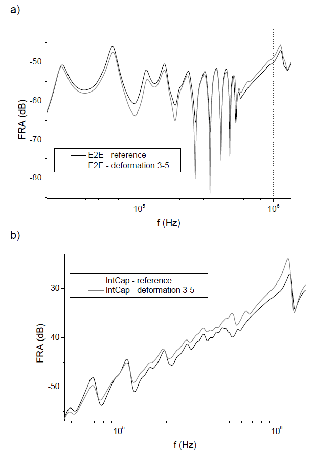
The third example of the deformation is given on Fig. 6 and represents lost spacers between discs (winding shrinkage). Similarly to the previous case both test systems give results having comparable changes after shrinking the winding. In E2E measurements there can be observed very large change of resonances damping (10-15 dB), while for IntCap results changes are again visible continuously in the whole presented frequency range.
The last fault introduced into tested winding are short-circuits of various scale. The examples of recorded frequency responses are presented on Fig. 7.
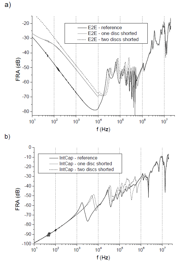
Shortcircuits in both test setups are easy to detect. The end-to-end open configuration has very good detection properties for short circuits between windings in low frequency range. Conducted tests in the capacitive interwinding test show the shifts resonances related to magnetic circuit (103-104 Hz) in the frequency domain and changes in transfer function along with increasing winding damage. Shortcircuits influence in both cases can be observed over a wide frequency range.
Conclusions
The research has shown the influence of the measuring system on detection and interpretation of introduced windings deformations. The most common configuration is end-to-end open, all introduced deformations are easy to detect and visible over a wide range of frequencies. This configuration is the basis for FRA testing and should be used for each case, it also recommended by IEC standard.
Capacitive interwinding tests show good detection efficiency over a wide frequency range. In presented results it showed even better sensitivity than E2E test setup. Changes in FRA curves are larger and visible in wider frequency range. Measurements carried out in this configuration should be made along with end-to-end open tests.
End-to-end shorted and inductive interwinding test setups have shown poor detection of deformation. The inductive interwinding test setup shows the effect of introduced faults in a very narrow frequency band which makes it difficult to observe and diagnose it. Elimination of the core response in end-to-end shorted setup affects the effectiveness of fault detection and interpretation, the received data on the transformer’s technical condition are incomplete.
In industrial practice there are usually measured two test setups: end-to-end open and end-to-end shorted. It is well knows and was proved in this paper that the second one is of no use. Instead there should be used interwinding capacitive test setup, which gives completely different response, based on capacitive interaction between two windings.
Two suggested test setups: end-to-end open and interwinding capacitive give together a very good dataset for further analysis. Some information on winding geometry can be obtained only from IntCap test setup.
FRA results are still hard to interpret, especially for cases without earlier measurement data. The application of E2E and IntCap test setups in the analysis will improve diagnosis quality. Authors are working on the method of concurrent interpretation of results coming from these two test setups.
REFERENCES
[1] Banaszak S., Ocena stanu mechanicznego części aktywnej transformatorów metodą analizy odpowiedzi częstotliwościowej, Wydawnictwo Uczelniane ZUT w Szczecinie, 2016
[2] Fairouz M., Yousof M., Ekanayake C., Frequency response analysis to investigate deformation of transformer winding, IEEE Transactions of Dielectrics and Electrical Insulation, vol. 22 (2015), no. 4, pp. 2359–2367
[3] IEC 60076-18:2012, Power transformers – Part 18: Measurement of frequency response, International standard.
[4] Banaszak S., Analiza odpowiedzi częstotliwościowej uzwojeń transformatorów w świetle zaleceń projektu normy IEC 60076-18, Pomiary Automatyka Kontrola, 57 (2011), nr 4, s. 413-416
[5] IEEE Guide for the Application and Interpretation of Frequency Response Analysis for Oil-Immersed Transformers, IEEE Std C57.149-2012, (2013), pp. 1-72.
Authors: M.Sc. Wojciech Szoka, West Pomeranian University of Technology, Department of Electrotechnology and Diagnostics, al. Piastów 17, 70-310 Szczecin, Poland, e-mail: wojciech.szoka@zut.edu.pl,
D.Sc. Szymon Banaszak, West Pomeranian University of Technology, Department of Electrotechnology and Diagnostics, al. Piastów 17, 70-310 Szczecin, Poland,
prof. Konstanty M. Gawrylczyk, West Pomeranian University of Technology, Department of Electrotechnology and Diagnostics, al. Piastów 17, 70-310 Szczecin, Poland
Source & Publisher Item Identifier: PRZEGLĄD ELEKTROTECHNICZNY, ISSN 0033-2097, R. 94 NR 7/2018. doi:10.15199/48.2018.07.10
