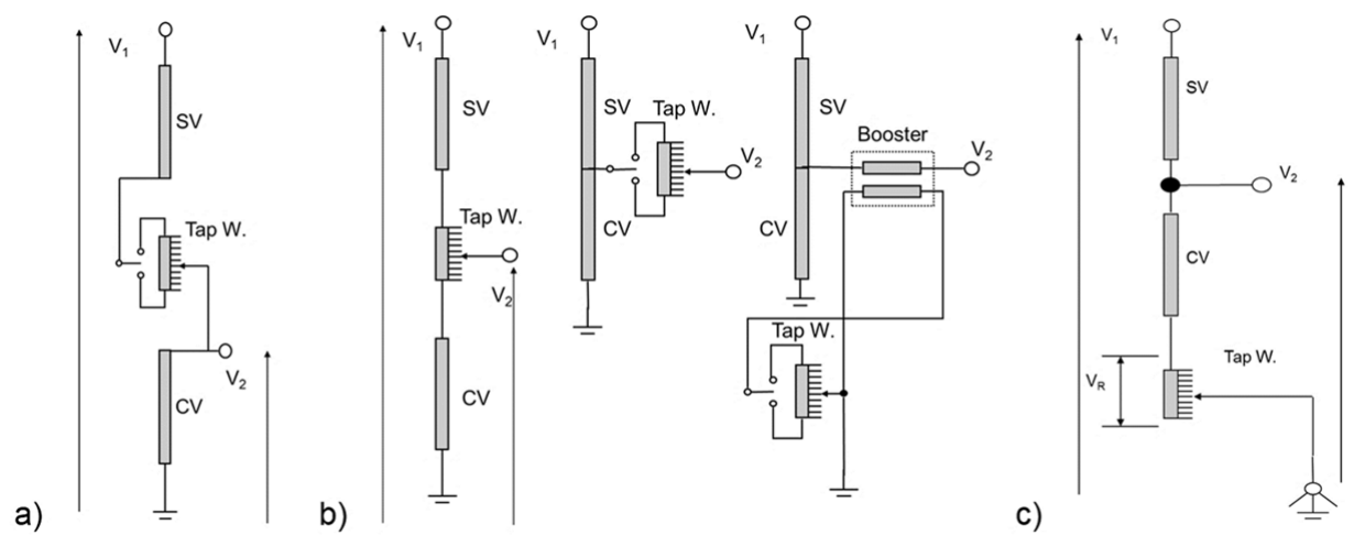
Previous Image Next Image fig.2.-voltage-variation-schemes-with-ltc-placed-in-a-hv-circuit-b-lv-circuit-c-neutral