Published by Piotr GAJEWSKI, Wrocław University of Science and Technology, Department of Electrical Machines, Drives and Measurements
Abstract. The paper presents the improved control strategy for Wind Energy Conversion System (WECS) during voltage sags. The considered back-to-back converter system includes: Ma-chine Side Converter (MSC) and Grid Side Converter (GSC) with control circuits. To the wind turbine the direct driven Permanent Magnet Synchronous Generator (PMSG) has been connected. In the control of MSC the modified Direct Torque Control (DTC) has been applied. The modified Direct Power Control (DPC) for control of GSC has been used. Under the voltage sags, the control circuits of MSC and GSC are forced to fulfil the Low-Voltage Ride Through (LVRT) requirements. The constant DC link voltage during grid faults is achieved by storing the surplus active power in the mechanical system inertia of the wind turbine. The effectiveness of considered control methods have been tested by simulation studies during unsymmetrical voltage sags. The obtained simulation studies confirmed good performance of applied control methods. The application of positive sequence components of grid voltage vector allows to reduce influence of unsymmetrical voltage sags.
Streszczenie. W artykule przedstawiono zmodyfikowaną strategie sterowania przekształtnikowym układem elektrowni wiatrowej podczas zapadu napięcia sieci AC. Przekształtnikowy układ elektrowni wiatrowej składa się z: Przekształtnika Maszynowego (PM), Przekształtnika Sieciowego (PS) oraz układów sterowania. Do turbiny wiatrowej został przyłączony bezprzekładniowy generator synchroniczny o magnesach trwałych (PMSG). Do sterowania PM zastosowano zmodyfikowaną metodę bezpośredniego sterowania momentem generatora (DTC). Do sterowania PS zastosowano zmodyfikowaną metodę bezpośredniego sterowania mocą (DPC). Podczas występowania zapadów napięcia sieci AC zmodyfikowano układy sterowania PM i PS w celu spełnienia wymagań LVRT. W celu utrzymania stałego napięcia w obwodzie pośredniczącym DC zastosowano metodę pozwalająca na zgromadzonej nadwyżki energii kinetycznej w łopatach turbiny wiatrowej. W celu potwierdzenia dużej skuteczności rozpatrywanych metod sterowania przeprowadzono badania symulacyjne. Uzyskane wyniki badań symulacyjnych potwierdzają dużą skuteczność zaproponowanych metod sterowania. (Zmodyfikowana strategia sterowania przekształtnikowym układem elektrowni wiatrowej z generatorem PMSG podczas zapadów napięcia sieci AC).
Keywords: wind turbine, PMSG, DTC, DPC, simulation studies.
Słowa kluczowe: turbina wiatrowa, PMSG, DTC, DPC, badania symulacyjne.
Introduction
Wind energy has become one of the largest and the fastest growing renewable energy sources because of its large reserves and non-pollution effects [1, 2]. In this growing trend, the influence of WECS to the AC grid become very significant. Therefore, the Grid Connection Requirements (GCR) should be updated gradually for power systems operators [3, 4]. Nowadays, the requirements on the power quality are higher than before [4]. The power growing of installed Wind Energy Conversion System (WECS) and the increased requirements of GCR for connecting wind turbines to the distribution systems enforce the analysis for possible influences of faults of WECS during voltage sags [5, 6]. According to the standards, the voltage sags can be defined as the sudden temporary reductions of the RMS (Root Mean Square) voltage magnitude at a point of electrical system [7]. The voltage sags may arise from huge currents caused by many grid faults, including connection of large loads or grid shortcircuits [8, 9]. During the voltage sags, the shutdown of wind farm may have a significant effect on the operation of distribution system. For this reason, the new rules of GCR should be determined. This Low-Voltage Ride Through (LVRT) requirements determine the behaviour of WECS during the voltage sags. Therefore, it is important to investigate a suitable method to enhanced the LVRT capability of WECS with direct-driven permanent magnet synchronous generator (PMSG) [10, 11]. The configuration of WECS with PMSG and full-scale back-to-back converter system has been shown in Figure 1. The presented configuration consists of: wind turbine, PMSG generator, Machine Side Converter (MSC), Grid Side Converters (GSC), grid filter and control circuits. The AC side of MSC is connected to the stator of direct driven PMSG. As results of low speed of PMSG generator, the gearbox usually is not applied. In the recent years, in the WECS the gearbox is characterized as most a faulty element of the system [11, 12]. The AC side of GSC is connected through the L (Lowpass filter) to the AC grid [13, 14]. The main function of MSC control is to extract the maximum power of wind turbine and to control of PMSG. The MSC controls the torque and the reactive power of PMSG [14]. The GSC control the DC link voltage and control the active and reactive power delivered to the AC grid [15, 16]. During voltage sags, operation of control of the converters can be disturbed. The voltage sags have harmful influence of WECS.

To avoid disturbed operation of WECS during voltage sags the LVRT requirements have been developed [17]. The LVRT requirements determine, that the WECS during voltage sags should be remain connected to the distribution system for specified time. The time of stay connected of wind turbine system can be illustrated in LVRT characteristic. The characteristic of LVRT requirements for WECS connected to the distribution system under voltage sags has been presented in Figure 2 [18, 19].

The presented characteristic defines two operating regions of WECS during voltage sags. The I region assumes of specific period, when WECS allows to stay connected to the system under voltage sags, therefore the II region concerns of specific period of disconnection of wind turbine system for distributed system. During voltage sags, when the voltage will not cross line below the minimal voltage dedicated by the line and this voltage will return to 90% on rated voltage within 1s, WECS must stay connected to the system. However, when voltage sags occurred in II region, the WECS should be disconnected from system. The disconnection of WECS during operation in II region, may have negative effect on the distribution system. The specification of periods of connection and disconnection of WECS during voltage sags can be different for individual countries [21].
The current LVRT rules also required, that the WECS beside the remain connected to the distribution system during voltage sag, should also support distribution system by delivery of the reactive power [17, 18].
The value of reactive power delivery to the AC grid is mostly determined by depth of voltage sags. In the Figure 3 the characteristic of Reactive Current Injection (RCI) by WECS under voltage sags has been shown [4, 7, 17].
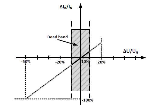
The value of the reactive current delivered to the AC grid can be designated directly in agreement with on the base of the characteristic presented in Fig. 3. The slope of the injected current curve is determined by different operators on distribution power system [4, 17].
The aim of this article is to carry on study of the WECS behaviour during the voltage sags. The influence of unsymmetrical voltage sags for operation of WECS has been analysed. In the control scheme of WECS, the novelty control algorithms have been applied in order to meet LVRT requirements with high accuracy.
Wind turbine model
The mathematical relation for the amount mechanical power Pt extraction by wind turbine can be expressed as follows [5, 10]:

where: ρ – air density; A=πR2 – area swept by the rotor blades; R – radius of the turbine blade; Cp – power coefficient of the wind turbine; λ – tip speed ratio; β – blade pitch angle; vw – wind speed.
The wind turbine power coefficient Cp is a nonlinear function of tip speed ratio λ and blade pitch angle β. The tip speed ratio can be shown as [6]:
The Figure 4 shows the power coefficient Cp as the function of tip speed ratio λ and blade pitch angle β. As it can be noticed, for each value of angle β the optimal tip speed ratio λopt exists at which the power coefficient Cp has the maximum value Cpmax.

The mechanical torque Tt of wind turbine can be described as:

The characteristics of the wind turbine operating at various wind speeds have been shown in Figure 5 [6]. The presented wind power characteristics represent the wind turbine power curves as function of rotor angular speed ωm at various wind speeds vw. According to Figure 5, it can be determined, that for each wind speed, the maximum power point can be achieved. This operation of Maximum Power Point Tracking (MPPT) is achieved, during wind turbine will be operating at optimal rotor angular speed ωopt.

When wind speed exceeds the rated wind speed, the power of wind turbine should be reduced by application of pitch angle control or stall and active stall control algorithm [10].
Permanent magnet synchronous generator model
In order to formulation developed the mathematical model of PMSG the following assumptions have been included [10]. The typical assumptions for modelling of PMSG have been presented in the literature [10, 14]. The mathematical model of PMSG is considered in synchronous rotating reference frame. The d axis is aligned with the direction of the rotor flux and the q axis is 90 ahead. The mathematical equations of the PMSG in dq frame can be described as follows [6, 10, 12]:

where: vsd, vsq – components of the stator voltage vector; isd, isq – components of the stator current vector; Ld, Lq – direct and quadrature stator inductances; Rs – stator resistance; ψPM – flux linkage established by the permanent magnets; np – number of pole pairs; ωe, ωm – electrical and mechanical angular speed of the PMSG rotor. The electromagnetic torque of PMSG can be expressed as:

When considering the assumption of equal inductances Ld=Lq=Ls, the torque equation can be presented in the form:
The dynamics equation of mechanical system with wind turbine and PMSG is formulated as:

where: J – the equivalent inertia, Kf – the coefficient of viscous friction.
Control of machine side converter
In the control scheme of MSC the Direct Torque Control (DTC) has been used. The operation of DTC is based on directly selecting the appropriate stator voltages vectors according to the differences between the reference and the actual values of magnitude of the stator flux vector and electromagnetic torque. In the regular DTC control is realize with three control loops. The outer control loop regulates the angular rotor speed of PMSG. Two inner control loops are responsible for control of the magnitude ψs of stator flux vector and the electromagnetic torque Te of PMSG. During voltage sags, the conventional DTC will not ensure the proper operation of WECS. Therefore, to achieve the LVRT condition, the operation of DTC should be modified.
In Figure 6 the modified control scheme of Direct Torque Control (DTC) of MSC has been presented. The operation of control scheme of MSC can be divided into: the normal operation and the operation during voltage sags.

During the normal operation the MSC control scheme is focused to achieve the maximum power from the wind. For this reason, the Maximum Power Point Tracking (MPPT) algorithm should be applied. During the operation at voltage sags, the control scheme of MSC is focused to fulfil the LVRT conditions. When the voltage sag has been detected, the change in the control scheme of MSC is forced in order to meet requirements.
In normal operation of WECS, the control scheme of MSC consists of three control loops with PI controllers. The outer control loop regulates the generator speed to track the optimum speed of wind turbine. The optimum speed ωmopt of wind turbine is obtained according to MPPT algorithm [6, 10]:

The MPPT technique has been used in order to obtain the maximum wind turbine mechanical power. The reference speed ωmopt is compared with measured ωm of PMSG. The error signal is sent to the PI controller. The output signal of PI controller determines the reference electromagnetic torque Te * of PMSG.
The inner control loops regulate the magnitude of stator flux vector ψs and the electromagnetic torque Te of PMSG. For an estimation of the magnitude of stator flux vector and the value of electromagnetic torque, several techniques have been found in literature [12].
The magnitude of stator flux ψs and electromagnetic torque Te of PMSG are compared with their reference values and are sent to PI controllers.
The outputs of PI controllers determine the reference components vsd *, vsq * of the stator voltage vector. These both signals are transformed to the reference components vsα * and vsβ * of the stator voltage vector for SVM control of MSC. The SVM block generates the required switching signals for MSC.
During operation, when voltage sag occurs, the control objective of MSC and GSC is switched. According to the LVRT requirements, during grid faults the operation control of MSC and GSC is focused to reduce the delivered active power to the AC grid. The reduction of active power allows to avoid the sustaining grid faults [4, 7, 12]. For this reason, the delivered active power by GSC and MSC should be reduced to the zero. During to the grid voltage sags, the maximum active power injected to the AC grid is reduced in proportion to the terminal voltage reduction and also can be limited by LVRT requirements [12].
When the grid faults have been identified, the “LVRT signal” generated by voltage detector is sent to switching control block “SB1” of MSC control. The application of switching block SB1 allows to change the control priority of MSC. The control loop of PMSG generator speed is disconnected. Instead of speed control loop of PMSG generator, the value of reference power pg * calculated by GSC scheme is delivered to the control of MSC. During the switching control loop, the regulation of DC link voltage vdc is realized by MSC control scheme. During the activation of this control operation, the value of PMSG electromagnetic torque is forced to near zero. This condition ensures, that the DC link voltage will be regulated at reference value. The reduction of electromagnetic torque of PMSG generator allows to reduce the PMSG power delivered to the MSC converter. The reduction of PMSG power by MSC control scheme, will cause the increase of the kinetic energy of inertia of WECS mechanical system [2, 14]. This increase will cause the increase of mechanical angular speed of wind turbine and PMSG. The final value of the increased speed of PMSG and wind turbine can be established from the equation of dynamic power Pd in the mechanical system [4, 7]:
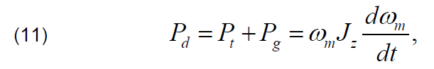
where: Pg – generator power; Pt – wind turbine power. The reduction of Pg power without reducing the Pt power will cause the rise of surplus power in the system. This surplus power will cause the increase of the angular rotor speed of generator from ωm to ωmk which can be found as [7]:
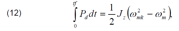
where: ωmk – the angular rotor speed of PMSG at the final instant of time of voltage sag; Jz – total inertia of mechanical system of wind turbine; tf – duration of voltage sag.
The value of angular rotor speed ωmk of the PMSG at the final moment of duration of the voltage sag at the condition of constant power Pd, can be expressed as:

The values of total wind turbine inertias Jz in typical designs of WECS are very high. The speed changes caused by the switching of the control system will be slow and small.
Control of grid side converter
In Figure 7 the control scheme of GSC has been presented. The operation of GSC can be divided into two control modes: the mode of normal operation and the mode of operation during voltage sags.
During the normal operation, the main control objective of GSC is to control the delivered power to the AC grid and control DC link voltage vdc [20]. In the mode of operation during voltage sags, the control aim of GSC is to reduce the delivered power to the AC grid and support the AC grid by injection of reactive current [4, 17].
The improved Direct Power Control (DPC) for GSC has been applied. In the mode of normal operation, the control scheme of GSC consists of three control loops with PI controllers. The outer control loop regulates the DC link voltage. The reference voltage vdc * is compared with measured DC link voltage vdc. The signal error is sent to the PI controller. Grid Side

The signal value from PI controller designates the reference component idg * of the grid current vector. The value of idg * is multiplied by measured DC link voltage vdc in order to obtain the reference active power pg * of AC grid. Two inner control loops regulate the instantaneous active power pg and reactive power qg. The instantaneous active power pg and reactive power qg in the stationary αβ frame can be estimated as follows [10, 15]:


where: vgα, vgβ – components of the grid voltage vector; igα, igβ – components of the grid current vector. The reference active power pg * is compared with estimated power pg of AC grid. The error signal is sent to the PI controller which determines the reference voltage vgcd * of GSC. The second inner control loop regulates the instantaneous reactive power qg of AC grid. The output of PI controller determines the reference voltage vgcd * of GSC. The reference reactive power qg* is compared with estimated reactive power qg of AC grid. In the mode of normal operation, the reference instantaneous reactive power is forced as zero qg *=0 to achieve the operation at the unit power factor. The error signal is sent to PI controller. The output of PI controller determines the reference voltage vgcq * of GSC. The obtained converter reference voltages vgcd *, vgcq * are then transformed to the stationary αβ system. The obtained converter reference voltages vgcα *, vgcβ * are sent to the block of Space Vector Modulation (SVM). The SVM block determines the reference switching signals for GSC.
When the voltage sags occur, the voltage detector generates the “LVRT fault signal”. This LVRT fault signal is delivered to the switch blocks: “SB2” and “SB3”. The LVRT signal delivered to the switch blocks enforce the change of the control scheme of GSC. The main priority of GSC is to meet the LVRT requirements. It means, that during the voltage sags, the GSC should ensure the proper control of instantaneous active power pg and reactive qg power according to LVRT requirements.
During the voltage sags, the control loop of DC link voltage is detached and then is attached to the MSC instead of speed control loop. The reference power pg* is sent to the control loop of MSC. In the literature the many different techniques can be described [7, 17]. In this article, according to LVRT demand it is assumed, that during voltage dips, the instantaneous active power should be enforced to be zero pgLIVRT *=0. It is also assumed, that the reactive power is delivered to the grid with accordance with RCI requirements [7].
Voltage dips occurred in AC grid can be divided into symmetrical and asymmetrical. During symmetrical and asymmetrical voltage sags, the positive, negative and zero sequence components occur in the system. In the literature, different control strategies for unsymmetrical voltage sags can be found [18]. During unsymmetrical voltage sags, it is necessary to use of symmetrical components in the control of GSC. The use of symmetrical components in the control of GSC, allows to avoid the consequence of unsymmetrical voltages sags, appearing with double oscillations in waveforms of instantaneous active and reactive power [7, 18]. In order to use of symmetrical components in the control scheme of GSC, the appropriate synchronization system should be applied. Typically, in the control scheme of DPC the angle of θg is determined by the Synchronous Reference Frame – Phase Locked Loop (SRF-PLL) block. However, the operation of SRF-PLL have only good properties during symmetrical grid voltage dips [15, 18]. When the unsymmetrical voltage occurs, the SRF-PLL it is not enough to obtain the proper grid angle of θg. In order to determine the proper grid angle θg it is necessary to use the improved SRF-PLL. In the literature different techniques are presented in order to independent harmful effect of unsymmetrical voltage dips. The one of the proposed solutions is the Double Decoupled Synchronous Reference Frame PLL (DDSRF-PLL). The DDSRF-PLL during unsymmetrical voltage sags, defines as unbalanced voltagevector, which is consisting of: positive and negative sequence components. The d axis of the synchronous reference frame has been aligned with the positive sequence vector components of the grid voltage (vqg +=0). This means, that the only positive-sequence current circulates through the L filter. The power controllers are implemented only for the positive sequence. The detailed description of applied DDSRF-PLL can be found in literature [16, 18].
In many works, it has been shown that an asymmetric voltage sags, may also have an influence on the waveforms of DC link voltage. For that reason, in the control scheme, the application of double harmonic oscillator filter for measured voltage is added. The use of this symmetrical components filter allows to avoid the double oscillation in waveforms of DC link voltages and also allows to reduce the electromagnetic torque ripple during switching control of MSC and GSC. In order to obtain better achievement of control circuit of GSC, the negative sequences of grid voltages vga -, vgb – are fed-forward to the reference positive sequence vgca +, vgcb + of GSC voltages.
Simulation results
The simulation results were conducted for WECS with PMSG. The simulation model of WECS with considered control circuits has been developed in MATLAB/Simulink using SimPowerSystem. The data of WECS used in simulation are presented as follows: rated power of wind turbine: Pt=20 kW; blade radius R = 4.4 m; air density ρ=1.225 kg/m3 and for 3-phase PMSG data and parameters: rated power Pg=20 kW; stator rated phase current Isn=35.1 A; rated speed nn= 210 rpm; stator resistance Rs= 0.1764 Ω; stator dq-axis inductance Ld=Lq=4.48 mH. The chosen simulation results of considered WECS are presented in Figures 8-9. In simulation it is assumed, that the considered WECS has been tested during the voltage sags in fixed wind speed.
The simulation results of control of GSC during low voltage sag are presented in Figure 8 The simulation results of control of MSC during low voltage sag are presented in Figure 9. In the Figure 8 the three phase grid voltages vgabc have been presented. It was assumed, that the voltage drops took place only in one phase.
The voltage drop of the voltage is equal to 50% of the reference voltage before the voltage sag. The voltage sag occurred at 0.15s and then in the 0.3s the grid voltage is starting recovery. In the Figure 8b the three phase grid currents igabc during voltage sag have been shown. It can be determined, that during unsymmetrical voltage sags, the applied control strategy allows to keep sinusoidal waveforms of grid phase currents. The obtained waveforms of grid currents igabc confirm the good performance of applied positive sequence control methods of GSC.
The waveforms oscillating instantaneous active pg and reactive qg power control results have been presented in Figure 8c. During the normal operation of WECS, the instantaneous reactive power is forced to zero qg=0. In this strategy, only the instantaneous active power is delivered to the AC grid and the operation at unity power factor has been achieved. However, when voltage sags have been detected, the priority of control has been reversed. The control strategy of WECS should fulfil the LVRT requirements. It means, that during the low voltage sag, the delivery of instantaneous active power is limited and is set to zero pgLVRT *=0 and instead of this the instantaneous reactive power qgLVTR * is delivered to the AC grid. In the Figure 8d the grid current vector components igd, igq have been presented.
The oscillations in waveforms of grid current vector igd, igq components have been eliminated by application of control scheme with positive sequence components.
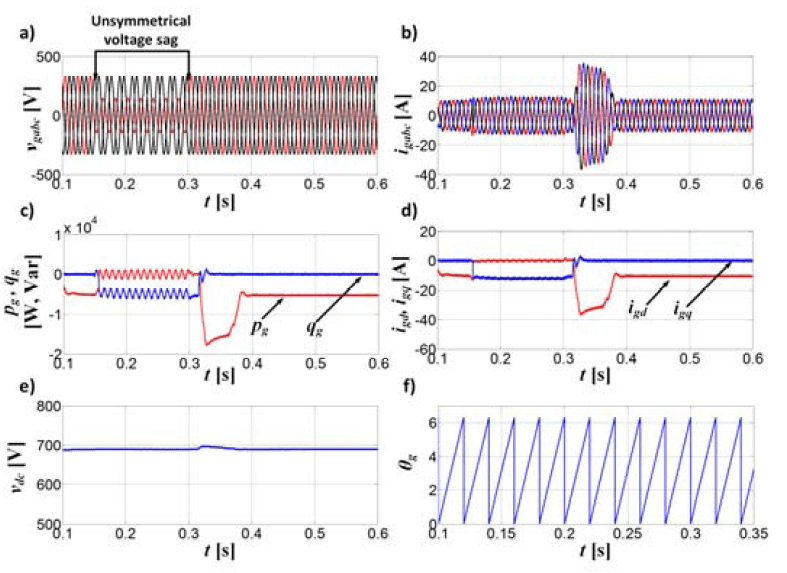
Fig.8. Waveforms of: a) grid phase voltages vgabc; b) grid phase currents igabc; c) instantaneous active and reactive power pg, qg; d) grid current vector components igd, igq; e) DC link voltages vdc; f) grid phase angle ϴg
The waveforms of DC link voltage vdc has been presented in Figure 8e. When the voltage sag is occurred, the DC link voltage is regulated by the MSC. In Figure 8f the waveforms of angle position θg of grid voltage vector, obtained from DDSRF have been illustrated. The application of DDSRF allows to determine the proper angle of grid voltage vector during unsymmetrical voltage sags.
In the Figure 9 the obtained results during voltage sags of MSC have been presented. In the Figure 9a the waveforms of reference speed ωopt and measured speed of generator ωm have been presented. During normal operation the measured speed tracks accurately the reference speed. In the control system, the reference speed is determined by the MPPT algorithm. However, during the voltage sags, the measured speed increased. The increasing speed of generator is caused by storage energy in inertia of wind turbine system [2, 3]. Due to reduction of electromagnetic torque to the zero, as consequence there is a torque mismatch in the mechanical system, which causes the speed to increase.

Fig.9. Waveforms of: a) reference speed ωopt and measured speed ωm of PMSG; b) electromagnetic torque Te of PMSG; c) trajectory of stator flux vector; d) magnitude of stator flux vector; e) real wind speed vw; f) tip speed ratio λ; g) power coefficient Cp of wind turbine
Figure 9b presents the responses of electromagnetic torque Te of PMSG. From this Figure, it can be noticed, that the electromagnetic torque Te during voltage sag is forced to zero, in order to reduce the PMSG power. This reduction of electromagnetic torque Te allows to keep the DC link voltage in the reference value and allows to keep balance the power between MSC and GSC.
The Figure 9c presents the waveforms of the magnitude ψs of stator flux vector and Figure 9d presents the trajectory of stator flux vector. From Figure 9c, it can be noticed that the stator flux vector rotates with a constant magnitude.
The reference wind speed trajectory is shown in Figure 9d. The waveforms of tip speed ratio λ and power coefficient Cp have been presented in Figure 9e-9f. From this Figure, it can be observed, that during normal operation of WECS the maximum power is obtained. During voltage sags, when the control of MSC and GSC are switched, it can be noticed, that the value of tip speed ratio is increasing while the power coefficient of wind turbine is decreasing.
After recovery voltage to the reference value, the MSC and GSC returns to the control of normal operation. The control objective of MSC is control of PMSG speed and obtain the maximum power. For GSC objective is control of DC link voltage and regulate the power.
Conclusions
In this paper the operation of WECS during the voltages sags has been considered. In the control of wind turbine system, the improved schemes of Direct Torque Control and Direct Power Control methods have been applied. The DTC with MPPT algorithm during normal operation of WECS allows to obtain the maximum power of wind turbine. The applied DPC control of GSC in normal operation ensures to regulates DC link voltage and adjust the active and reactive power of the system.
Under voltage sag, the priority of control methods of MSC and GSC has been changed. For regulation of PMSG power and DC link voltage is responsible MSC. The control method of GSC is focused to reduce the delivered power to AC grid and for injection of reactive power to the AC grid in order to meet the LVRT requirements. The application of switch control loops of DTC and DPC, during grid faults, allows to store the surplus energy in the rotor inertia of wind turbine.
The application of DDSRF-PLL allows to obtain the appropriate angular voltage vector position during the symmetrical and unsymmetrical voltage sags. To avoid oscillation in waveforms of DC link voltage and waveforms grid currents caused by the unsymmetrical voltage disturbances, the positive sequence components is only used in the control scheme of GSC. The proposed control methods have been verified by simulation studies.
REFERENCES
[1] Abdelrahem M., Mobarak M.H., Kennel R., Realization of low-voltage ride through requirements for PMSGs in wind turbines systems using generator-rotor inertia, International Conference on Electrical and Computer Engineering (ICECE), Dhaka, pp. 54-57 (2016).
[2] Nasiri M., Milimonfared J., Fathi S.H., A review of low-voltage ride-through enhancement methods for permanent magnet synchronous generator based wind turbines, Renewable and Sustainable Energy Review, no. 47, pp. 399-415 (2015).
[3] Ibrahim R. A., Hamad M. S., Dessouky Y. G., Williams B.W., A review on recent low voltage ride-through solutions for PMSG wind turbine, International Symposium on Power Electronics, Electrical Drives, Automation and Motion, Sorrento, pp. 265- 270 (2012).
[4] Gajewski P., Pieńkowski K., Control of wind turbine system with PMSG for low voltage ride through, International Symposium on Electrical Machines, IEEE Xplore, SME, pp. 1-6 (2018).
[5] Muyeen S.M., Takahashi R., Murata T., Tamura J., A variable speed wind turbine control strategy to meet wind farms grid code requirements, IEEE Transactions on Power Systems, vol.25, no. 1, pp. 331-340 (2010).
[6] Ki-Hong K., Yoon-Cheul J., Dong-Choon L., Heung-Geun K., LVRT scheme of PMSG wind power systems based on feedback linearization, IEEE Transactions on Power Electronics, vol. 27, no. 5, pp. 2376-2384 (2012).
[7] Alepuz S., Calle A., Busquets-Monge S., Kouro S., Wu B., Use of stored energy in PMSG rotor inertia for low-voltage ride-through in back-to-back NPC converter-based wind power systems, IEEE Transactions on Industrial Electronics, vol. 60, no. 5, pp. 1787-1796 (2013).
[8] Zheng X., Liu Y., Liu Z., Li Y., Wang C., Feng Y., Coordinating control method to improve LVRT ability of PMSG, IEEE Conference on Industrial Electronics and Applications (ICIEA), Wuhan, pp. 1461-1465 (2018).
[9] Yan Z., Mingliang C., Zhen X., Li Xu., Wang W., An experimental system for LVRT of direct-drive PMSG wind generation system, IEEE 8th International Power Electronics and Motion Control Conference (IPEMC-ECCE Asia), Hefei, pp. 1452-1456 (2016).
[10] Gajewski P., Analysis of power converter system of wind turbine with permanent magnet synchronous generator, PhD thesis, Wrocław University of Science and Technology, (2018).
[11] Muyeen S.M., Takahashi R., Murata T., Tamura J., A variable speed wind turbine control strategy to meet wind farms grid code requirements, IEEE Transactions on Power Systems, vol. 25, no. 1, pp. 331-340 (2010).
[12] Dey P., Datta M., Fernando N., Senjyu T., Fuzzy-based Coordinated Control to Reduce DC-link Overvoltage of a PMSG based Wind Energy Systems during Grid Faults, International Conference on Electric Power and Energy Conversion Systems (EPECS), Kitakyushu, Japan, pp. 1-6 (2018).
[13] Muyeen S.M., Takahashi R., Murata T., Tamura J., Low voltage ride through capability enhancement of fixed speed wind generator, IEEE Bucharest PowerTech, pp. 1-6 (2009).
[14] Gajewski P., Pieńkowski K., Advanced control of direct-driven PMSG generator in wind turbine system, Archives of Electrical Engineering, vol. 65, no. 4, pp. 643-656 (2016).
[15] Zielonka P., Jasiński M., Bobrowska-Rafał M., Sikorski A., Sterowanie przekształtnika sieciowego AC-DC podczas zapadów w sieci elektroenergetycznej, Przegląd Elektrotechniczny, R.87, nr 6/2011, pp. 79-84 (2011).
[16] Rodriguez P., Pou J., Bergas J., Candela J. I., Burgos R. P., Boroyevich D., Decoupled Double Synchronous Reference Frame PLL for Power Converters Control, IEEE Transactions on Power Electronics, vol. 22, no. 2, pp. 584-592 (2007).
[17] Jarzyna W., Lipnicki P., The comparison of Polish grid codes to certain European standards and resultant differences for WWP requirements, EPE JOINT Wind Energy and T&D Chapters Seminar, pp. 1-6 (2012).
[18] Jarzyna W., Zielinski D., The impact of converter’s synchronization during FRT voltage recovery in two-phase short circuits, Selected Problems of Electrical Engineering and Electronics (WZEE), Kielce, pp. 1-6 (2015).
[19] Rizo M., Rodríguez A., Bueno E., Rodríguez F. J., Girón C., Low voltage ride-through of wind turbine based on interior Permanent Magnet Synchronous Generators sensorless vector controlled, IEEE Energy Conversion Congress and Exposition, Atlanta, pp. 2507-2514 (2010).
[20] Jasiński M., Kaźmierkowski M.P., Bobrowska M., Okoń P., Control of AC-DC-AC converter under unbalanced and distorted input conditions, Power Quality, Alternative Energy and Distributed System, pp. 139 – 145 (2009)
[21] Nguyen T. H., Lee D., Song S., Kim E., Improvement of power quality for PMSG wind turbine systems, IEEE Energy Conversion Congress and Exposition, Atlanta, GA, pp. 2763- 2770 (2010).
Author: Piotr Gajewski Ph.D., Wrocław University of Science and Technology, Department of Electrical Machines, Drives and Measurements, ul. Wybrzeże Wyspiańskiego 27, 50-370 Wrocław, piotr.gajewski@pwr.edu.pl
Source & Publisher Item Identifier: PRZEGLĄD ELEKTROTECHNICZNY, ISSN 0033-2097, R. 96 NR 4/2020. doi:10.15199/48.2020.04.26
