Published by Józef LORENC, Krzysztof ŁOWCZOWSKI, Bogdan STASZAK
Politechnika Poznańska, Instytut Elektroenergetyki
Abstract. In this paper possibilities for improvement of earth fault protection by adjustment of protective relay settings due to change of neutral point impedance in medium voltage networks are presented.
Streszczenie. W artykule przedstawiono zagadnienia dotyczące możliwości poprawy skuteczności działania zabezpieczeń ziemnozwarciowych typu YY0 poprzez dostosowanie wartości nastawczych do zmian spowodowanych modyfikacją sposobu pracy punktu neutralnego w sieci średniego napięcia. (Zabezpieczenia ziemnozwarciowe wspierane funkcjami adaptacyjnymi).
Słowa kluczowe: punkt neutralny, zwarcie doziemne, admitancja, elektroenergetyczna automatyka zabezpieczeniowa
Keywords: neutral point, earth fault, admittance, earth fault protection systems
Introduction
Admittance relay was developed in Poland in Institute of Electrical Power Engineering of Poznan University of Technology [1, 2, 3, 4, 5, 6]. Principle of operation is explained in [7] and [8]. First relays were implemented in distribution system networks at the end of XX century as an analogue construction. Nowadays admittance criterion is implemented in digital protection relays, which are installed in bays of 110/15 kV or medium voltage substations as an decision-making algorithm. Moreover some distribution system operators install admittance based fault passage indicators [9]. In Poland admittance relays are typically installed in compensated medium voltage networks. Another admittance based criteria for protection relays are in the development stage: i.e. Cumulative Phasor Summing [10 ,11] proposes centralized earth-fault protection based on measurements of zero sequence current and voltage. Despite of admittance criteria for detection of high impedance faults, another criteria are being analyzed i.e. [12] proposes wavelet based criteria. New fault feeder detection methods for a resonant grounding system are also presented in [13, 14, 15, 16].
YY0 relay presented in the paper is improvement of original admittance relay. Principle of YY0 relay operation is based on zero sequence admittance growth – ΔY0 during single phase to ground fault and after reconfiguration of an neutral point impedance. Start-up value is given by formula (1) and (2).

Where: SI1, SI3, SI4 – signals measured during earth fault before neutral point impedance reconfiguration, ΔYY0n –admittance growth setting, U0n – zero sequence voltage setting value.
Signals “S” are functions of zero sequence current and zero sequence voltage of lines during phase-to-ground fault. Signals S are described by the following formulas (3), (4), (5) and (6).


Signal S is connected to the zero sequence voltage input of the relay and is described by formula:

Coefficients ku, ki, ky and kn are used to convert zero sequence input signals. Coefficients ku, ki, and kn are dimensionless and describe a transformation ratio of instrument transformers (current and voltage transformers) and input divider, whereas ky represents admittance of additional voltage circuit.
Sensitivity of the relay depends on impedance of neutral point and does not depends on zero sequence impedance of line.
Application of active zero sequence current forcing arrangement (ACF) in compensated networks results in growth of measured admittance ΔY0 observed in faulted line, particularly in growth of conductance component – ΔG0, which is proportional to additional resistance connected in neutral point in parallel to Petersen coil.
Setting value of YY0 relay is typically in range of 50% of additional resistor conductance. According to operational experience from Poland relays operate effectively up to 2000 Ω of fault resistance. A reason for limited level of detected fault resistance is mostly due to loss of sensitivity of zero sequence voltage component presented in (2) and explained further in (8).
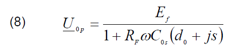
where: U0p – zero sequence measured voltage, EF – phase voltage of a network, RF – fault resistance, C0s – earth fault zero sequence capacitance, ω – angular frequency, d0 – damping coefficient of zero sequence impedance described as a ratio of zero sequence conductance and zero sequence susceptance (9), s – detuning coefficient of Petersen coil (10).

where: Ld – inductance of Petersen coil.
Analysis of formulas (7) and (8) clearly shows that sensitivity of zero sequence voltage component of YY0 can be improved by changing d0 and s or by decreasing U0n setting value during certain earth fault conditions. However reduction of U0n setting value can only be made during earth fault and after analysis of measured values therefore relay has to be additionally equipped with adaptive algorithm. Two methods of adaptive algorithms are presented in next paragraphs.
Decision making algorithm for shunt impedance connected to neutral point

Based on analysis of formula (7) it is clear that zero sequence voltage level for a given C0s and RF values strongly depends on damping coefficient – d0 and detuning factor – s. During operation of ACF value of d0 coefficient is increased. Alternatively instead of forcing resistor it is possible to connect forcing reactor (reactive zero sequence current forcing arrangement – RCF). In that case value of coefficient of earth fault current compensation detuning s is changed. In practice not only value of detuning factor s can be changed but also its sign.
Another possibility to change s is to disconnect coil, which is normally connected to neutral point of a grounding transformer. If RCF is used an additional criterion which analyses zero sequence susceptance growth of line is required. Therefore universal admittance characteristic presented in the figure 1 should be used. In order to include susceptance region in the characteristic, additional criterion has to be included in decision making algorithm. Criterion is analogical to (1), but signals in I0 current circuit are additionally shifted 90°. As a result characteristic presented in the Figure 1 is created. Area inside a rectangle characteristic (square) is non-operational area. ΔB0 states for susceptance growth necessary for relay operation and ΔG0 is conductance growth necessary for operation.
As is previously described RCF is similar to ACF, however operational experiences shows that in many situations RCF devices can be more effective than ACF. Especially in case of high impedance earth faults.
Fig. 2 presents RF = f(s) curves, which describe maximum earth fault resistance seen by YY0 relay in 15 kV compensated network with total ground fault current equals to 120 A. Analysis of curves allows us to conclude that in typical compensated polish networks with detuning factor lower than 0,1 region of detected fault can be significantly bigger if RCF device is used (curve 2) comparing to ACF (curve 1). A phenomena is explained by the fact that negative influence of RCF reactance on zero sequence voltage is lower than in case of ACF.
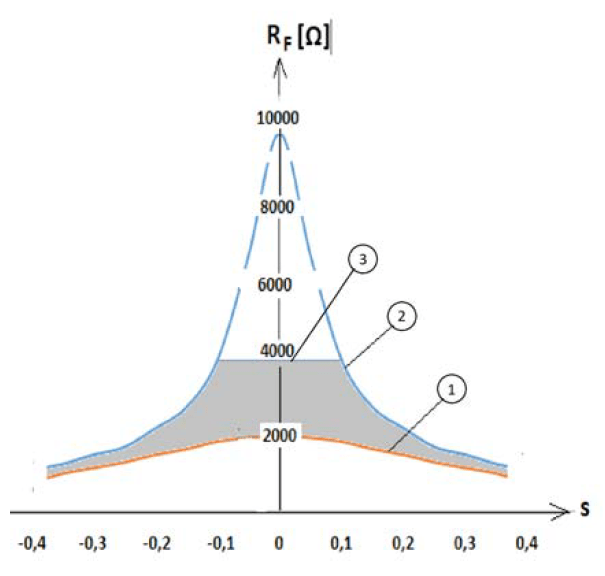
Curves 1 and 2 presents the effectiveness of YY0 relay for earth fault detection after operation of RCF or ACF which enforces 20% rise of a total earth fault current. It is assumed that U0n set value is 15% of phase voltage of a network. Moreover it is assumed that phase-to-ground capacitance is equal in all phases (symmetrical network) and natural damping factor d0 is smaller than 0,04.
In practice effectiveness of YY0 during operation of RCF device is limited by curve 3. Maximal effectiveness (4000 Ω) can be achieved when detuning coefficient after operation of RCF is reduced to 0,1. Following conditions can occur only when:
– network is undercompensated (detuning is no bigger than – 0,1; s = – 0,1) and after operation of RCF network becomes overcompensated (detuning factor is no bigger than 0,1),
– network is overcompensated (detuning factor is no bigger than 0,1; s = 0,1) and after operation of RCF network becomes undercompensated (detuning factor is no bigger than – 0,1; s = – 0,1).
Effectiveness of an earth fault detection is reduced for all other detuning factors. When operation of RCF results in relatively big detuning factor, an effectiveness of earth fault detection will be reduced to 2000 Ω so it will be lower than effectiveness after operation of ACF.
Adaptive algorithm of ACF and RCF compares different variants and choose a better one –ACF or ACF and optimal control of shunt impedance. It is recommended to reduce reactance of coil if network is undercompensated and to increase reactance when network is overcompensated. System for shunt impedance control is presented in the Fig. 3. Control algorithm, which is responsible for measuring voltage level and tuning of Petersen coil plays an important role in the system. RCF increases an earth fault current by connection of additional reactance LNW or reduce a ground fault current (reduce inductive current) by disconnecting a reactance, which is normally connected between neutral point of grounding transformer and a ground. In order to operate properly the system needs to measure detuning factor continuously. Commonly used systems for active compensation and passive systems for control of an earth fault parameters ensure access to necessary parameters.

Connection of additional resistance to neutral point is justified only when fault resistance is low (relatively big value of U0p – i.e. above 50% of phase voltage) or when detuning factor (absolute) is too big. It is also possible to make a decision about ACF activation based on level of natural asymmetry of a network.
Adaptive settings
As is explained in previous paragraphs an effectiveness of YY0 operation is limited by sensitivity of zero sequence voltage component. In typical polish networks start-up values of voltage are in range of 0,15-0,2 of phase voltage. Specific value is determined by natural phase-to-ground asymmetry of a network and resonance effect during normal operating conditions of a network. As a result of the phenomena voltage is increased permanently during normal operation conditions. Voltage rise is described by formula (11).

where: Uasn – voltage resulting from zero-sequence leakage and natural asymmetry, U0rez – voltage resulting from resonance effect between phase-to-ground capacitance of a network and Petersen coil.
One can clearly observe that an amplitude of the voltage could be easily reduced by increasing d0 and s factors. The detuning is however not recommended since an earth fault current extinguishing capabilities of a Petersen fault are reduced. The best condition to extinguish an electric arc can be observed when coefficient of detuning of earth fault current compensation equals 0 – coil current fully compensates a capacitive current of a network. Consequently to reduce negative aspect of resonance effect it is only possible to apply devices, which increase phase-to-ground damping factor. In typical compensated medium voltage networks in Poland and typical ACF systems damping can be raised to approximately 0,2, in these way a voltage resulting from resonance effect is reduced a few times. As a result less restricted requirements could be used during selection of U0n starting values. Reduction of U0n settings usually improves effectiveness of YY0 relay and increases the range of detected high impedance faults.
Voltage effects resulting from operation of ACF became the foundation for development of conductance protection decision algorithm making in Institute of Electrical Power Engineering of Poznan University of Technology. Adaptive functions are included in this algorithm [8]. Similar functions can be implemented in YY0 relay, which operates according to following rules:
– adaptive function is activated only during resistance fault and when U0p is below Uon after operation of ACF device,
– setting value is changed only after additional resistive component of a current is detected (effect of ACF operation), – when adaptive function is activated a set value of voltage criterion is reduced and setting of conduction rise is increased,
– reduction of U0p is between 15% to 5% of phase voltage,
– a value of conductance rise depends on ratio of U0p measured before and after operation of PFR and typically is lower than 150% of base value
After taking into account defined network parameters a performance analysis of YY0 with adaptive function is performed. Partial results of the analysis are presented in the table 1.
Table 1. Values of fault resistance detected by YY0 relay with adaptive function
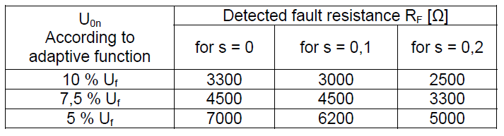
One can easily notice that thanks to adaptive settings during harsh conditions – high resistance faults (above a few thousands ohms), an effectiveness of earth fault detection is significantly increased. Possibility of reduction U0n setting to 0,05 in well compensated network allows for detection of earth faults with fault resistance above 7000 Ω. In case of networks with a big share of overhead lines and capacitive current in range of 80 – 90 A the effectiveness can be even higher – up to 10000 Ω.
REFERENCES
[1] Lorenc J., Marszałkiewicz K., Andruszkiewicz J., Admittance Criteria for Earth Fault Detection in Substation Automation Systems in Polish Distribution Power Networks. CIRED, Birmingham (1997), Publication IEEE, No. 438 (1997)
[2] Florkowski W., Lorenc J., Maćkowiak M., Musierowicz K., Sposób i układ wybiorczego zabezpieczenia od jednofazowych zwarć z ziemią w sieci o małym prądzie ziemnozwarciowym, Patent PL Nr 116699
[3] Lorenc J., Rakowska A., Staszak B., Limitation of Earth-Fault Disturbances and their Effects in Medium Voltage Overhead Lines. Przegląd Elektrotechniczny, no. 4 (2007), ss. 75-79
[4] Lorenc J., Torbus M., Staszak B., Automatyczna sterowanie kompensacją ziemnozwarciową w sieciach SN przy wykorzystaniu miernika parametrów ziemnozwarciowych, Wiadomości Elektrotechniczne, no. 12 (2013)
[5] Lorenc J., Musierowicz K., Sposób i układ do pomiaru stopnia skompensowania prądu ziemnozwarciowego w sieciach kompensowanych średniego napięcia, Patent PL Nr 150320
[6] Lorenc J., Staszak B., Wiśniewski A., Sposób i układ do wykrywania zwarć wysokooporowych w liniach pracujących w kompensowanej sieci średniego napięcia, Patent PL Nr 226282.
[7] Lorenc J., Admitancyjne zabezpieczenia ziemnozwarciowe. Wydawnictwo Politechniki Poznańskiej,j (2007)
[8] Wahlroos A., Altonen J., Compensated networks and admittance based earth fault protection, ABB library, (2011)
[9] Altonen J., Wahlroos A., Performance of Modern Fault Passage Indicator Concept in Compensated MV-Networks, CIRED Workshop – Helsinki, (2016)
[10] Wahlroos A., Altonen J., Application of Novel Multi-frequency Neutral Admittance Method into Earth-Fault Protection in Compensated MV-networks, 12th IET International Conference on Developments in Power System Protection, (2014)
[11] Balcerek P., Fulczyk M., Rosołowski E., Iżykowski J., Pierz P., New algorithm for determination of faulty feeder in distribution network, 11th IET International Conference on Developments in Power Systems Protection, (2012)
[12] Michalik M., Rebizant W., Łukowicz M., Lee S.-J. Kang S.H., Wavelet Transform Approach to High Impedance Fault Detection in MV Networks, IEEE Russia Power Tech, (2005)
[13] Mou-Fa Guo, Nien-Che Yang, Features-clustering-based earth fault detection using singular-value decomposition and fuzzy c-means in resonant grounding distribution systems, Electrical Power and Energy Systems 93 (2017), ss. 97–108
[14] Xiangning Lin, Shuohao Ke, Yan Gao, Bing Wang, Pei Liu, A selective single-phase-to-ground fault protection for neutral uneffectively grounded systems, Electrical Power and Energy Systems, 33 (2011), ss. 1012–1017
[15] Wahlroos A., Altonen J., Pekkala H-M., Post-fault oscillation phenomenon in compensated MV-networks challenges earth-fault protection, 23rd International Conference on Electricity Distribution, Lyon, (2015)
[16] Linčiks J., Baranovskis D., Single Phase Earth Fault Location in the Medium Voltage Distribution Networks, Scientific proceedings of Riga Technical University, The 50th International Scientific Conference Power and electrical engineering, (2009)
Authors: prof. dr hab. inż. Józef Lorenc, Politechnika Poznańska, Instytut Elektroenergetyki, ul. Piotrowo 3a, 60-965 Poznań, E-mail: jozef.lorenc@put.poznan.pl; mgr inż. Krzysztof Łowczowski, Politechnika Poznańska, Instytut Elektroenergetyki, ul. Piotrowo 3a, 60-965 Poznań, E-mail: krzysztof.lowczowski@put.poznan.pl; dr inż. Bogdan Staszak, Politechnika Poznańska, Instytut Elektroenergetyki, ul. Piotrowo 3a, 60-965 Poznań, E-mail: bogdan.staszak @put.poznan.pl;
Source & Publisher Item Identifier: PRZEGLĄD ELEKTROTECHNICZNY, ISSN 0033-2097, R. 94 NR 8/2018. doi:10.15199/48.2018.08.31
