Published by Joanna KOZIEŁ, Lublin University of Technology, Institute of Electrical Engineering and Electrotechnologies
Abstract. The paper presents the classification of superconducting fault current limiters. In particular the principle of construction and operations of superconducting current limiter of transformer type is presented. Functional physical model of such a limiter, designed, manufactured in the Laboratory of Superconducting Technologies of Institute of Electrical Engineering. The paper presents the results of experimental research and the analysis of the impact of the secondary winding limiter on the performance of superconducting current limiters of a transformer type and the conclusions from the analysis are introduced.
Streszczenie. W artykule zawarto klasyfikację nadprzewodnikowych ograniczników prądu zwarcia. W szczególności przedstawiono zasadę budowy i działania nadprzewodnikowego ogranicznika prądu typu transformatorowego. Omówiono funkcjonalny model fizyczny takiego ogranicznika zaprojektowany wykonany w Pracowni Technologii Nadprzewodnikowych Instytutu Elektrotechniki. Przedstawiono wyniki badań eksperymentalnych, analizę wpływu uzwojenia wtórnego ogranicznika na parametry nadprzewodnikowych ograniczników prądu typu transformatorowego i przedstawiono wynikające z analizy wnioski. (Analiza wpływu impedancji uzwojenia wtórnego na parametry nadprzewodnikowych ograniczników prądu typu transformatorowego).
Słowa kluczowe: nadprzewodnictwo, ograniczenie prądu zwarcia, nadprzewodnikowy ogranicznik prądu typu transformatorowego, impedancja uzwojenia wtórnego.
Keywords: superconductivity, limiting of short circuit current, transformer type superconducting fault current limiter, the impact of secondary winding impedance.
Introduction
Superconducting fault current limiters – SFCL are composed of superconducting elements of alternating impedance, being connected in series in an electrical circuit [1], [2]. They show a low impedance while operating in rated conditions of a protected electrical circuit, and high impedance in short circuit conditions in a protected circuit [3].

The rapid return of capabilities to limit the current after the disappearance of short circuit and long life together with low operating costs are the main advantages of superconducting fault current limiters.
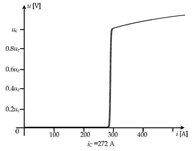
The SFCL superconducting elements work in both the superconducting and in the resistive state. The requirements for SFCL superconducting materials are different than in the case of other superconducting devices intended to operate only in the superconducting state (Fig. 1) [1],[6].
The classification of superconducting fault current
limiters Literature distinguishes between the following superconducting fault current limiter types:
• resistive limiter,
• inductive limiter [2],[7-10],
• a) systems with an open magnetic core [11], b) systems with a closed magnetic core,
• transformer type [12],[13].
You can accept the idea that the transformer type superconducting fault current limiter is a variation of the inductive type superconducting fault current limiter with a magnetic core. The transformer type superconducting fault current limiters have many advantages over resistance and inductive ones because they do not require current culverts, as it is the case of resistance limiters, and do not require secondary superconducting winding either, as it is the case of inductive limiters. In the transformer type superconducting fault current limiters the secondary winding impedance value of a limiter will increase the short circuit impedance during the short circuit, consequently the short circuit current will be limited to the value resulting from the parameters of the superconducting element used. The degree of reduction of the current in the transformer type superconducting fault current limiters is sufficient to limit the short circuit current with very large values.
The principle of the construction and operation of transformer type superconducting fault current limiter
Fig. 2 shows the idea of the construction and operation of transformer type superconducting fault current limiter. The limiter in question is composed of a conventional transformer with copper winding and of a superconducting element R2, shorting the secondary winding of a conventional transformer. The superconducting element is usually an inductor or a bifilar coil, wound with the HTS superconducting tape. The primary copper transformer winding is connected in series with the protected circuit of power grid and the secondary winding is shorted with the HTS superconducting coil, with the critical current value equal to the admissible value of the current of the protected circuit. When the current in the secondary winding of the conventional transformer exceeds, as a result of a short circuit, the value of the critical current of the superconducting winding, the winding loses superconductivity and transits into the resistive state. The HTS coil transition to a resistive state occurs rapidly. Within a few microseconds, the resistance of the secondary side of the transformer and the transformer type superconducting current limiter “changes” in the reactor limiting the current in the protected circuit. With such an activity of the limiter, the short circuit/fault current does not achieve its primary maximum, which protects electrical equipment, especially transformers, from the effects of mechanical forces that can damage the device mechanically.
I1 – current of the primary side of the transformer, I2 – current of the secondary side of the transformer, U1 – voltage of the primary side of the transformer, U2 – voltage of the secondary side of the transformer, L1 – self-inductance of the primary side, L2 – self-inductance of the secondary side, US – mains voltage, M – mutual inductance of windings, ZL – load, R2 – resistance of the superconducting limiting element.
If the value of the current of the power transmission line I1, which is equal to the current value of the primary side of the serial transformer, is small then the current limiter has a very low impedance (in the superconducting state), because RHTS = 0.
During the short circuit, as a result of the increase in the value of the I1 current the limiter has a high impedance (a resistive state), because the resistance of the superconducting element is significantly higher than zero RHTS> 0 [15].
Design and construction of transformer type superconducting fault current limiter model
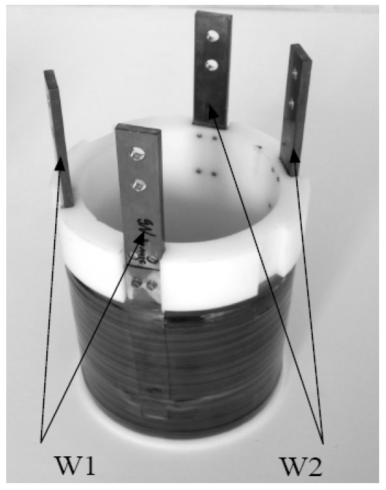
In the Laboratory of Superconducting Technologies of Institute of Electrical Engineering a functional model of a single-phase transformer type superconducting fault current limiter model was designed and constructed [16].
The limiter consists of a conventional 10 kVA transformer with copper secondary winding shorted with a superconducting element (Fig.3). Table 1 shows the Cu conventional transformer model parameters.
Table 1. Parameters for a transformer model with conventional Cu windings [16].
The superconducting element is a superconducting coil composed of two independent windings w1, w2 wound on a common bobbin. This structure allows the configuration of the superconducting element to operate with different values of resistance and inductance of windings: winding w1 or w2 windings connected in series or in parallel – either compatibly or contrarily.
This allows you to determine the effect of the parameters of the superconducting element on the process of limiting the current by a limiter. Superconducting windings are cooled in a bath of liquid nitrogen. The parameters of the superconducting windings are given in Table 2.
Table 2. Parameters for superconducting coils composed of two independent windings w1 and w2 made of HTS 2G SCS4050 [16]
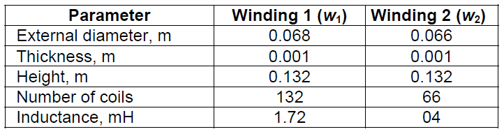
Both windings are made of HTS 2G SCS4050 superconducting tape produced by SuperPower. This is a tape with a width of 4 mm and a thickness of 0.055 mm [16],[18-20] laminated on both sides with copper, with a critical current Ic = 150 A. Maximum rated current of the superconducting windings is equal to the effective value of the critical current of the superconductor amounting to 82 A.
Laboratory research for transformer type superconducting fault current limiter model
Experimental research was conducted in order to verify the possibility to limit the short circuit current by the transformer type current limiter and to determine the level of the current limit with respect to the parameters of the superconducting element (HTS windings configuration) [12]. The research was conducted in Laboratory of Superconducting Technologies in the measurement system shown in Fig. 6.
The superconducting fault current limiter model is powered by a voltage regulator connected to the power network in separate transformer. The shunts used to perform the current measurement have a value of 1 mV/1 A. The measurements were performed with the use of a measuring PC DAQ Card and LabView software. The short circuit was initiated by the short circuit system. The time of short circuit is 0.05 s.
The analysis was performed for the following superconducting winding configurations w1 and w2:
Configuration I – the secondary winding of the Cu transformer shorted with w1 coil, Configuration II – the secondary winding of the Cu transformer shorted with w2 coil; Configuration III – the secondary winding of the Cu transformer shorted with w1 and w2 coils connected in parallel.
The electrical parameters of windings for each configuration of HTS coils are shown in Table 3.
Table 3. The parameters of superconducting windings for the three configurations of windings w1 and w2 [16].

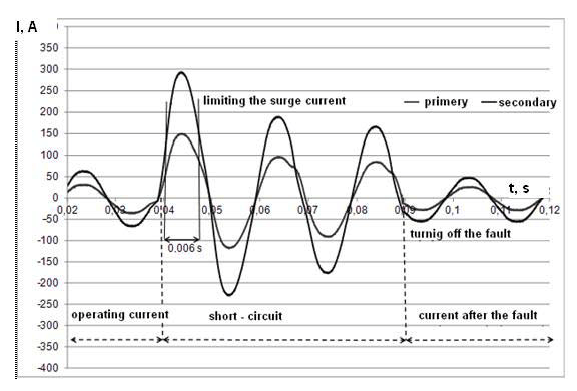
Fig. 7 shows the current waveforms on the primary and secondary side of the limiter for the selected configuration of the windings. After the current in the secondary winding of the Cu transformer has crossed the critical current value of the superconducting winding, the surge current (the first impulse of the short circuit current) is limited to the value resulting from the value of the short circuit impedance of the limiter – ZZW (ISC).
The comparison of the primary current waveforms obtained for all the HTS configurations of the windings shown in Figure 8 compares the number of times the limited surge current exceeds the value of the critical current of the superconducting winding.

The short circuit impedance of the limiter Zzw (ISC), is the sum of Cu transformer impedance – ZzwCu (ISCCu) and superconducting winding impedance ZHTS. If we assume for simplicity that ZzwCu (ISCCu) has a constant value, then the impedance value Zzw (ISC) depends on the reactance value XHTS and the resistance RHTS of the HTS winding, thus on the configuration of the winding and on the resistance of the superconducting tape used at the temperature of 77 K. The higher the RHTS and XHTS value, thus the value of the superconducting winding impedance the greater the limitation of the short circuit current. The time after which the limited surge current reaches the expected value of the short circuit current set, for configuration II of the HTS winding, amounts to about 6 ms.
Conclusions
The analyses conducted and experimental research results show that it is possible to build a transformer type superconducting fault current limiter, using the existing conventional transformer with the secondary winding shorted by the superconducting winding made of HTS tape.
The level of limiting the short circuit current, especially the first impulse of the surge current, depends on the value of the short-circuit impedance of the limiter, being the sum of the Cu transformer impedance and HTS winding impedance. HTS winding impedance depends on the winding configuration (inductors or bifilar coils, or many coils connected in series or in parallel), and also on the resistance of the superconducting tape. Selecting the proper HTS tape as well as the appropriate configuration of the superconducting winding, on the assumption of the constant value of the Cu transformer impedance, it is possible to build a transformer type superconducting fault current limiter with a desired level of limiting the short circuit current.
Acknowledgments. I sincerely thank my the promoter prof. Tadeusz Janowski you for any help, patience, kindness during the implementation of my doctoral thesis and my colleagues from the Laboratory of Superconducting Technologies of Institute of Electrical Engineering.
REFERENCES
[1] Janowski T., Stryczewska H.D., Kozak S., Malinowski H., Wojtasiewicz G., Surdacki P., Kondratowicz-Kucewicz B., Kozak J.: Nadprzewodnikowe ograniczniki prądu, Wydawnictwo LIBER, Lublin, 2002
[2] Cieśla A.: Nadprzewodnictwo w stulecie odkrycia: wybrane
przykłady zastosowań, Przegląd Elektrotechniczny, R. 87, nr 12a/2011, s.1–4
[3] Kacejko P., Machowski J.: Zwarcia w systemach elektroenergetycznych, WNT, Warszawa, 2012.
[4] Kozieł J.: The influence of magnetic coupling factor k on value of impedance limiting fault current, Przegląd Elektrotechniczny, R.85 NR 5/2009, pp. 200–203
[5] Janowski T., Stryczewska H.D., Wac- Włodarczyk A.: Technologie nadprzewodnikowe i plazmowe w energetyce, Lubelskie Towarzystwo Naukowe, Lublin, 2009
[6] Kozak J., Majka M., Kozak S., Janowski T.: Comparison of Inductive and Resistive SFCL, IEEE Transactions on Applied Superconductivity, vol. 23., No.3, 2013, article number 5600604
[7] Kozak J., Majka M., Janowski T., Kozak S., Wojtasiewicz G., Kondratowicz-Kucewicz B., Test and performance analysis of coreless inductive HTS fault current limiter, IEEE Trans. Appl. Supercon., 21, 2011, pp. 1303–1306
[8] Kozak J., Majka M., Kozak S., Janowski T.: Design and Test of Coreless Inductive Superconducting Fault Current Limiter, IEEE Transactions on Applied Superconductivity, Vol.22, No.3, June 2012,article number 5601804
[9] Kozak J., Majka M., Janowski T., Kozak S.: Nadprzewodnikowy bezrdzeniowy indukcyjny ogranicznik prądu zwarciowego średniego napięcia, Przegląd Elektrotechniczny, R.88 NR 9b/2012, s.245-248
[10] Kozak S., Janowski T., Wojtasiewicz G., Kozak J., Kondratowicz-Kucewicz B., Majka M., The 15 kV Class
Inductive SFCL, IEEE Transactions on Applied Superconductivity., 20, 2010, pp.1203-1206
[11] Kalsi S., Superconducting Transformers, Webster J., (ed), Willey Enc. of El. and Electr. Online, Copyright © 1999 by John Willey & Sons, Inc.
[12] Wojtasiewicz G., Janowski T., Kozak S., Kozak J., Majka M., Kondratowicz-Kucewicz B., Experimental Investigation of a Model of a Transformer Type Superconducting Fault Current Limiter with a Superconducting Coil Made of a 2G HTS Tape, IEEE Transactions on Applied Superconductivity, Vol. 24 No.3, 2014, pp.1788-1790
[13] Janowski T., Kozak S., Kondratowicz-Kucewicz B., Wojtasiewicz G., and Kozak J.: Analysis of Transformer Type Superconducting Fault Current Limiters, IEEE Transactions on Applied Superconductivity, Vol. 17, No. 2, 2007, pp. 1788–1790
[14] Kozieł J, Janowski T.: The Project of Transformer Type of Superconducting Fault Current Limiter, 5th International Conference: Electromagnetic Devices and Process in Environment Protection- ELMECO-5, Nałęczów, 2005, Conference Proceedings, Lublin, 2008, pp. 237–243
[15] Kozak S., Wojtasiewicz G., Kondratowicz-Kucewicz B., Kozak J., Majka M., Czerwiński D., Łanczont M., Surdacki P., Nadprzewodniki w urządzeniach elektroenergetycznych, Przegląd Elektrotechniczny, nr 5/2013, 338-345
[16] Kozieł J.: Analiza wpływu impedancji uzwojenia wtórnego na parametry nadprzewodnikowych ograniczników prądu typu transformatorowego, rozprawa doktorska, Politechnika Lubelska, Wydział Elektrotechniki i Informatyki, Lublin 2014.
[17] Janowski T., Kozieł J., Giżewski T., Czerwiński D.: Modelowanie powrotnej charakterystyki rozgałęzionej taśmy nadprzewodnikowej HTS 2G, Przegląd Elektrotechniczny, R.88 NR 7a/2012, s. 168–171
[18] Kozak S., Janowski T., Materiały nadprzewodnikowe dla nadprzewodnikowych ograniczników prądu, Prace Naukowe Instytutu Podstaw Elektrotechniki i Elektrotechnologii Politechniki Wrocławskiej, nr 44, 2006
[19] Majka M., Kozak J., Janowski T., Kozak S.: Analiza skuteczności działania bezrdzeniowych indukcyjnych
nadprzewodnikowych ograniczników prądu wykonanych z taśmy nadprzewodnikowej pierwszej i drugiej generacji, Przegląd Elektrotechniczny, R.88 NR 8/2012, str.32-35
[20] Majka M., Kozak S.: Zastosowanie taśm I i II generacji do budowy nadprzewodnikowych ograniczników prądu, Przegląd Elektrotechniczny R. 87, NR 5/2009, s.183-185
Autor: dr inż. Joanna Kozieł, Lublin University of Technology, Electrical Engineering and Computer Science Faculty, Institute of Electrical Engineering and Electrotechnologies, Lublin ul. Nadbystrzycka 38A, 20-618 Lublin, E-mail: j.koziel@pollub.pl
Source & Publisher Item Identifier: PRZEGLĄD ELEKTROTECHNICZNY, ISSN 0033-2097, R. 92 NR 12/2016. doi:10.15199/48.2016.12.20
