How To Choose The Right System Earthing Arrangement?
Application Note, 2009
Published by Schneider Electric
Source: https://www.se.com/ww/en/download/document/DBTP72ART_EN/
All System Earthing Arrangements (SEA) provide equivalent protection of life and property. However each has certain advantages and inconveniences in other terms that may be important for a given installation.
In both commercial and industrial applications, needs change, and it is becoming increasingly important to choose the right system earthing arrangement, according to rigorously defined working practices, in order to ensure the cohabitation of “high and low currents” and satisfy the operator’s requirements.
Following a review of the risks related to installation insulation faults affecting the safety of persons and equipment, this Technical Guide describes the three types of system earthing defined by standards IEC 60364 and NF C 15.100. Each system earthing arrangement is examined in terms of safety and availability, as well as for its protection against overvoltages and electromagnetic disturbances.
Changing Needs
Today, the three system earthing arrangements, defined by standards IEC 60364 and NF C 15.100, are:
- the TN system
- the TT system
- the IT system.
All three systems have the same final purpose as regards protection of persons and equipment: control of insulation fault effects. They are considered as equivalent with respect to the protection of persons against indirect contact. The same is not necessarily true for the dependability of the LV electrical installation regarding:
- availability of the electrical power supply
- maintenance of the installation.
These calculable parameters are becoming increasingly important in industrial and commercial premises.
Causes of Insulation Faults
In order to ensure protection of persons and continuity of operation, the conductive wires and live parts of an electrical installation are “insulated” from the earthed exposed conductive parts.
Insulation involves:
- separation by insulating materials
- separation by linear clearances in gases
(e.g. in air) or by creepage distances along insulators (e.g. to prevent flashover on electrical switchgear).
Insulation is characterised by specific voltages which, in accordance with standards, apply to new products and equipment: insulation voltage (highest voltage on system) lightning impulse withstand voltage (1.2/50 μs impulse wave) power frequency withstand voltage
(2U + 1000 V/1 min).
Example for an LV switchboard of the Prisma type:
- insulation voltage: 1000 V
- impulse voltage: 12 kV.
When commissioning a new installation, produced in accordance with standard working practices with products manufactured as per standards, the risk of an insulation fault is extremely low. However, this risk increases with time. This is because the installation is subjected to a variety of aggressions which are responsible for insulation faults. Below are a few examples:
during installation:
- mechanical deterioration of a cable insulator
during operation:
- dust with a varying degree of conductivity
- the thermal ageing of insulators due to excessive temperature caused by:
- the climate
- too many cables in a duct
- an insufficiently ventilated cubicle
- harmonics
- overcurrents…
- the electrodynamic forces developed during a short-circuit which may damage a cable or reduce a clearance
- switching and lightning surges
- 50 Hz voltage surges caused by MV earth faults and affecting LV equipment.
Normally, it is a combination of these primary causes which results in an insulation fault.
This fault can be either:
- a differential mode fault (between the live conductors) in which case it becomes a short-circuit
- or a common mode fault (between live conductors and the exposed conductive parts or earth). A fault current, referred to as a common mode or zero-sequence fault (MV), then flows in the protection conductor (PE) and/or in the earth.
System earthing arrangements in LV are mainly concerned by common mode faults which occur most frequently in loads and cables.
Risks Linked to the Insulation Fault
Whatever its cause, an insulation fault is a risk to life property and the availability of electrical power: all this comes under the heading of dependability.
Risk of electric shock
A person (or animal) subjected to an electrical voltage, is electrified.
| Current | Effects on the human body |
|---|---|
| 1A | Cardiac arrest |
| 75mA | Irreversible cardiac fibrillation threshold |
| 30mA | Respiratory paralysis threshold |
| 10mA | Muscular contraction (tetanisation) |
| 0.5mA | Very slight sensation |
Protection of persons against the dangerous effects of electrical current takes top priority; the risk of electric shock must therefore be taken into account before the rest.
Risk of fire
Should this risk materialise, it can have serious consequences for persons and equipment. Many fires are caused by an excessive temperature rise at a specific time or an electrical arc generated by an insulation fault.
The higher the fault current, the greater the risk. This risk also depends on the degree of the fire or explosion risk on the premises.
Risk of unavailability of electrical power
Control of this risk is becoming increasingly important. This is because if the faulty part is automatically disconnected in order to eliminate the fault, the results are:
- a risk for people, for example:
- sudden loss of lighting
- shutdown of vital equipment
- an economic risk due to production loss. This risk must particularly be controlled in process industries for which restarting can be long and costly.
Moreover, if the fault current is high:
- the damage, in the installation or the loads, can be serious and increase repair costs and time
- the circulation of high fault currents in the common mode (between the system and earth) can also disturb sensitive devices, particularly if they are part of a “low current” system which is geographically spread out with galvanic links.
Finally, on de-energisation, the appearance of overvoltages and/or electromagnetic radiation phenomena can cause malfunctioning or even deterioration of sensitive equipment.
A Few Reminders
Terminology
In this chapter the electric shock and electrocution risks are specified for the various system earthing arrangements, as defined by the International Electrotechnical Committee in standard IEC 60364.
The system earthing arrangement in LV characterises the earthing of the secondary of the HV/LV transformer and the earthing of the exposed conductive parts of the installation. Identification of the types of system earthing arrangements is thus defined by 2 letters:
- the first letter for connection of the transformer neutral (2 possibilities):
- T for “earthed”
- I for “unearthed” (or “isolated”)
- the second letter for the type of connection of the exposed conductive parts of the installation (2 possibilities):
- T for “directly” earthed
- N for “connected to earthed neutral” at the origin of the installation.
The combination of these two letters gives three possible configurations:
| Transformer neutral | Exposed conductive parts |
| If T | T or N |
| If I | T |
i.e. TT, TN and IT.
Terminology (cont.)
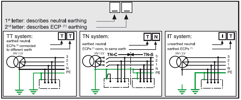
Note 1: The TN system, according to IEC 60364 and standard NF C 15-100, has several sub-systems:
- TN-C: if the N neutral and PE conductors are combined (PEN)
- TN-S: if the N neutral and PE conductors are separate
- TN-C-S: use of a TN-S downstream of a TN-C (the opposite is forbidden).
Note that the TN-S is compulsory for systems with conductors of a cross-section y 10 mm2 Cu.
Note 2: Each system earthing arrangement can be applied to an entire LV electrical installation. However, several arrangements can jointly exist in the same installation.
Example of a simplified earth leakage current (Id) calculation
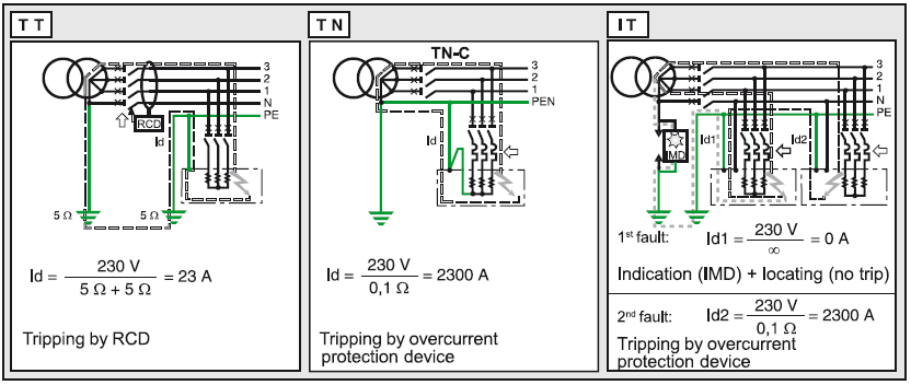
TT In the presence of an insulation fault, the fault current Id is limited for the most part by the earthing resistances (if the earthing connections for the exposed conductive parts and for the neutral are not combined). This fault current induces a fault voltage in the load earthing resistances. Since the earthing resistances are normally low and of the same order of magnitude (≅10Ω), this voltage of around Uo/2 is dangerous. The part of the installation concerned by the fault must therefore be automatically disconnected by an RCD.
TN In the presence of an insulation fault, the fault current Id is only limited by the impedance of the fault loop cables. For 230/400 V systems, this voltage of the order of Uo/2 (if RPE = Rph) is dangerous as it is greater than the limit safety voltage, even in dry environments (UL = 50V). The installation or part of the installation must then be immediately and automatically de-energised by an RCD. As the insulation fault is similar to a phase-to-neutral short-circuit, breaking is performed by the overcurrent protection devices.
IT Behaviour on the 1st fault
- Since the neutral is unearthed, there is no flow of a fault current Id. Voltage is not dangerous, and the installation can therefore be kept in operation
- As the IMD (Insulation Monitoring Device) has detected this 1st fault, it must be located and eliminated before a 2nd fault occurs.
Behaviour on the 2nd fault
- The fault concerns the same live conductor: nothing happens and operation can continue
- The fault concerns two different live conductors. The double fault is a short-circuit (as in TN). Breaking is performed by the overcurrent protection devices.
TT This system sustains the “earth fault” … but limits the consequences by implementing residual current devices which detect the earth fault before it becomes a short-circuit. This is the principle of the TT “directly earthed neutral” systems which allow the addition of extra outgoers by simply combining them with an RCD.
It is the safety champion!
- In this case, as for short-circuits, the only contribution that can be made to availability is to enhance discrimination by installing several stages of earth leakage protection in order to reduce breaking to the smallest part of the system.
- Note that RCDs are: v built into or added to the circuit breaker and switch with the 0.5 to more than 100 A Multi 9 range
- built into the circuit breaker with the 100 to 630 A Vigi module
- built into the circuit breaker with the insulation monitoring module
- with separate toroid with the 100 to 6300 A Vigirex devices which indicate absence of auxiliary supply source without causing tripping (avoids resets), and also warn the user of the insulation drop without causing tripping, by means of an early warning contact which is activated at half of the displayed threshold. For example: set at 300 mA, it warns the user at 150 mA.
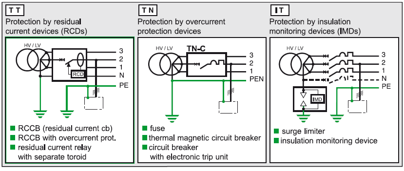
TN When a fault occurs, this system causes tripping of the SCPD (short-circuit protective
device) to provide protection. This fault is similar to a short-circuit (very low fault loop impedance) and is thus violent and destructive. The circuit breaker therefore trips on the 1st fault.
- This is the principle of the TN systems with exposed conductive parts connected to the
neutral earthing point and which do not require additional protection devices such as RCDs
or IMDs. It is thus the installation economy champion! This principle quickly becomes costly in the event of modifications or extensions, and is hard on installations due to short-circuit effects on cables and loads, as well as voltage drops which can disturb computers, MN undervoltage releases, motors, …
- In order to limit the consequences of the fault to the part of the system concerned, current, time and energy discrimination methods must be implemented.
- When the fault loop impedance is poorly controlled, it may be necessary to add additional protection of the residual current type. The NEC (National Electrical Code) requires earth-fault protection of TN-S systems by GFP (ground fault protection) devices or low-sensitivity RCDs. Moreover, the use of medium-sensitivity RCDs (300 mA) can also reduce the risk of fire by eliminating stray currents.
- An extensive choice of 1P/3P/4P circuit breakers provides a perfect solution from 1 to more than 6300 A with the following ranges:
- Multi 9
- Compact
- Masterpact
IT This system renders the fault inoffensive. It consists of attacking the cause rather than the effect by limiting the fault current to a few mA. In an IT unearthed neutral or impedant neutral system, as the fault is not dangerous, there is no need to trip and operation can continue.
It is the electrical power availability champion!
- However, leaving an earth fault on such a system would mean leaving a direct link between
the system and the earth, as before. In this case, the appearance of a 2nd fault creates a dangerous current which must cause tripping of the same kind as in the TT and TN system earthing arrangements.
- For this reason, this type of unearthed neutral system is only advantageous if real insulation faults are detected as soon as they appear by the Vigilohm System range which automatically and immediately detects faults on outgoers, including transient faults (which users particularly dread). This is the function of the XM200 IMD with the XD301 detectors (1 outgoer) or XD312 detectors (12 outgoers) combined with closed A toroids.
- In order to meet the needs of sites with the most exacting availability requirements, Schneider Electric offers products designed to measure resistance and capacitance outgoer by outgoer.
These products communicate this information locally and via the supervision system, and make it possible to implement preventive maintenance so as never to be subjected to the earth fault. These protection devices are: XM300C, XD308C, XL308, XL316, and the local XAS, XL1200, XL1300, XTU300 interfaces according to the installation configuration.
Switchgear

System Earthing Arrangement Choice Criteria
Their performance is evaluated according to the five criteria listed below:
- protection against electrical shocks
- protection against electrical fires
- continuity of supply
- overvoltage protection
- protection against electromagnetic
- disturbances.
A summary of the properties of each system earthing arrangement results in the following technical comparison.
Protection against electrical shocks
All the system earthing arrangements guarantee equal protection against electrical shocks provided that they are implemented and used according to standards.
Protection against the risk of electrical fires.
In the TT and IT system earthing arrangements, when the first insulation fault occurs, the current generated by this fault is low or very low respectively, and the risk of fire is slight.
On the other hand:
- in the event of a full fault, the current generated by the insulation fault is high in the TN type system earthing arrangements, and the resulting damage is serious.
- in the event of an impedant fault, the TN system earthing arrangements implemented without residual current devices do not provide sufficient protection, and use of the TN-S system earthing arrangement combined with residual current devices is recommended.
- in normal operation, the TN-C system earthing arrangement presents a higher risk of fire than the others.
This is because the load unbalance current permanently flows through not only the PEN conductor but also the devices connected to it: metal frameworks, exposed conductive parts, shieldings, etc.
When a short-circuit occurs, the energy lost in these stray trajectories considerably increases. For this reason the TN-C system earthing arrangement is forbidden on premises where there is a risk of fire or explosion.
Continuity of supply
Choice of the IT system earthing arrangement avoids all the harmful consequences of the insulation fault:
- the voltage sag
- the disturbing effects of the fault current
- damage to equipment
- opening of the faulty outgoer.
If this system earthing arrangement is used correctly, the second fault is highly unlikely.
Note: it is always a combination of measures that helps ensure continuity of supply: dual power supply sources, UPS, discrimination of protection devices, IT system earthing arrangement, maintenance department, etc.
Overvoltage Protection
Protection may be necessary in all system earthing arrangements. Choice of the right protection must take site exposure and the type and activity of the establishment into account. It is then necessary to determine the number and quality of necessary equipotential zones in order to implement the protection devices required (surge arresters, etc.) on the lines of the various incoming and outgoing electrical systems.
Remarks:
- the IT system earthing arrangement more often requires the use of surge arresters
- no system earthing arrangement completely does away with these measures
- in the IT system earthing arrangement, protection against overvoltages due to MV faults must be provided by a surge limiter.
Protection Against Electromagnetic Disturbances
Any system earthing arrangement can be chosen:
- for all differential mode disturbances
- for all disturbances (common or differential mode) with a frequency greater than a MHz.
The TT, TN-S and IT system earthing arrangements can thus satisfy all electromagnetic compatibility criteria. However, it should be noted that the TN-S system generates more disturbances during the insulation fault, as the fault current is higher.
On the other hand, the TN-C and TN-C-S system earthing arrangements are not recommended, as in these systems a permanent current due to load unbalance flows through the PEN conductor, the exposed conductive parts and the cable shieldings. This permanent current creates disturbing voltage drops between the exposed conductive parts of the sensitive equipment connected to the PEN. The presence of 3rd order multiple harmonics has considerably amplified this current in modern installations.
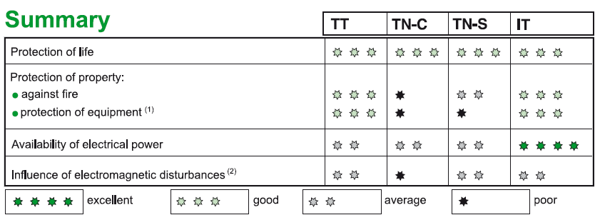
(2) All electromagnetic disturbances:
• external: faults on HV distribution system, switching surges, lightning surges, etc.
• internal: insulation fault currents, harmonics in LV installations.
Choice of System Earthing Arrangement and Conclusion
The common aim of the three system earthing arrangements internationally used and standardised by the IEC 60364 is maximum dependability.
As regards protection of persons, all 3 system earthing arrangements are equivalent provided that all installation and operating rules are complied with.
Given the specific characteristics of each system earthing arrangement, it is impossible to make a choice without considering installation and operating needs.
This choice must be the result of joint deliberation between the user and the system designer (electrical consultants, contractor, …) on:
- the installation characteristics
- operating conditions and requirements.
It is pointless trying to operate an unearthed neutral system in part of an installation which, by its very nature, has a low insulation level (a few thousand ohms): old and extended installations, installations with external lines…
Likewise, it would be a contradiction in industry where continuity of supply and productivity are essential and fire risks high, to choose a multiple earthed neutral system.
How to Choose the Right System Earthing Arrangement
- First and foremost, do not forget that all three system earthing arrangements can exist side by side in the same electrical installation. This is a guarantee that the best solution for safety and availability needs will be found for every case.
- You must then ensure that the choice of system earthing arrangement is not recommended or imposed by standards or legislation (decrees, ministerial orders).
- You then need to dialogue with the user in order to identify his needs and means:
- need for continuity of supply
- whether or not there is a maintenance department
- risk of fire.
- Generally speaking:
- continuity of supply and a maintenance department: the solution is an IT system
- continuity of supply and no maintenance department: there is no completely satisfactory
solution: prefer a TT system for which discrimination on tripping is easier to implement
and which minimises damage compared with a TN system.
- Extensions are easy (no calculations)
- continuity of supply is not essential and there is a competent maintenance department:
prefer a TN-S system (rapid repairs and extension according to rules) - continuity of supply is not essential and there is no maintenance department: prefer a TT system
- risk of fire: IT if there is a maintenance department, and use a 0.5 A RCD, or TT
- continuity of supply is not essential and there is a competent maintenance department:
- Take the special features of the system and loads into account:
- very extensive system or with a high leakage current: prefer TN-S
- use of replacement or standby power supplies: prefer TT
- loads sensitive to high fault currents (motors): prefer TT or IT systems
- loads with low natural insulation (furnaces) or with a large HF filter (large computers): prefer a TN-S system
- supply of control and monitoring systems: prefer an IT (continuity of supply) or TT system (enhanced equipotentiality of communicating devices).
Conclusion
Using only one system earthing arrangement is not always the best choice. In many cases it is thus preferable to implement several system earthing arrangements in the same installation.
As a rule, a “radial” installation, with careful identification of priority loads and use of standby sources or uninterruptible power supplies, is preferable to a tree-structured monolithic installation.
We hope this technical guide has furthered your knowledge of system earthing arrangements and that it will enable you to optimise the dependability of your installations.

Pretty! This has been an extremely wonderful post. Thanks for providing these details.
LikeLike
You are so interesting! I do not suppose I’ve read through a single thing like this before. So wonderful to find somebody with some unique thoughts on this subject. Really.. thank you for starting this up. This site is something that is required on the web, someone with a little originality!
LikeLike
Hi I am so grateful I found your blog, I really found you by accident, while I was searching on Aol for something else, Anyhow I am here now and would just like to say thank you for a incredible post and a all round enjoyable blog (I also love the theme/design), I don’t have time to browse it all at the moment but I have book-marked it and also added your RSS feeds, so when I have time I will be back to read much more, Please do keep up the fantastic job.
LikeLike